Page 4753 of 5121
TM-280
< ECU DIAGNOSIS >[CVT: RE0F10A]
TCM
JCDWM0249GB
Page 4754 of 5121
TCM
TM-281
< ECU DIAGNOSIS >[CVT: RE0F10A]
C
E
F
G
H
I
J
K
L
MA
B
TM
N
O
P
JCDWM0250GB
Page 4755 of 5121
TM-282
< ECU DIAGNOSIS >[CVT: RE0F10A]
TCM
JCDWM0251GB
Page 4756 of 5121
TCM
TM-283
< ECU DIAGNOSIS >[CVT: RE0F10A]
C
E
F
G
H
I
J
K
L
MA
B
TM
N
O
P
Fail-safeINFOID:0000000003806489
The TCM has an electrical fail-safe mode. In this mode TCM is operates even if there is an error in a main
electronic control input/output signal circuit.
FAIL-SAFE FUNCTION
If any malfunction occurs in a sensor or solenoid, this function controls the CVT to make driving possible.
JCDWM0252GB
Page 4757 of 5121
TM-284
< ECU DIAGNOSIS >[CVT: RE0F10A]
TCM
Output Speed Sensor (Secondary Speed Sensor)
The shift pattern is changed in accordance with throttle position when an unexpected signal is sent from the
output speed sensor (secondary speed sensor) to the TCM. The manual mode is inhibited, and the transaxle
is put in “D”.
Input Speed Sensor (Primary Speed Sensor)
The shift pattern is changed in accordance with throttle position and secondary speed (vehicle speed) when
an unexpected signal is sent from the input speed sensor (primary speed sensor) to the TCM. The manual
mode is inhibited, and the transaxle is put in “D”.
PNP Switch
If an unexpected signal is sent from the PNP switch to the TCM, the transaxle is put in “D”.
CVT Fluid Temperature Sensor
If an unexpected signal is sent from the CVT fluid temperature sensor to the TCM, the gear ratio in use before
receiving the unexpected signal is maintained or the gear ratio is controlled to keep engine speed under 5000
rpm.
Transmission Fluid Pressure Sensor A (Secondary Pressure Sensor)
If an unexpected signal is sent from the transmission fluid pressure sensor A (secondary pressure sensor) to
the TCM, the secondary pressure feedback control is stopped and the offset value obtained before the non-
standard condition occurs is used to control line pressure.
If transmission fluid pressure sensor A (secondary pressure sensor) error signal is input to TCM, secondary
pressure feedback control stops, but line pressure is controlled normally.
Pressure Control Solenoid A (Line Pressure Solenoid valve)
If an unexpected signal is sent from the solenoid to the TCM, the pressure control solenoid A (line pressure
solenoid valve) is turned OFF to achieve the maximum fluid pressure.
Pressure Control Solenoid B (Secondary Pressure Solenoid valve)
If an unexpected signal is sent from the solenoid to the TCM, the pressure control solenoid B (secondary pres-
sure solenoid valve) is turned OFF to achieve the maximum fluid pressure.
Torque Converter Clutch Solenoid valve
If an unexpected signal is sent from the solenoid to the TCM, the torque converter clutch solenoid valve is
turned OFF to cancel the lock-up.
Step Motor
If an unexpected signal is sent from the step motor to the TCM, the step motor coil phases “A” through “D” are
all turned OFF to hold the gear ratio used just before the non-standard condition occurred.
CVT Lock-up Select Solenoid valve
If an unexpected signal is sent from the solenoid to the TCM, the CVT lock-up select solenoid valve is turned
OFF to cancel the lock-up.
TCM Power Supply (Memory Back-up)
Transaxle assembly is protected by limiting the engine torque when the memory back-up power supply (for
controlling) from the battery is not supplied to TCM. Normal status is restored when turning the ignition switch
OFF to ON after the normal power supply.
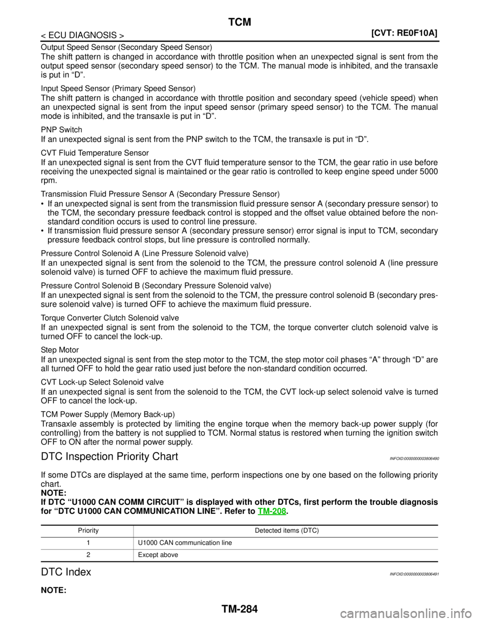
DTC Inspection Priority ChartINFOID:0000000003806490
If some DTCs are displayed at the same time, perform inspections one by one based on the following priority
chart.
NOTE:
If DTC “U1000 CAN COMM CIRCUIT” is displayed with other DTCs, first perform the trouble diagnosis
for “DTC U1000 CAN COMMUNICATION LINE”. Refer to TM-208
.
DTC IndexINFOID:0000000003806491
NOTE:
Priority Detected items (DTC)
1 U1000 CAN communication line
2 Except above
Page 4758 of 5121
TCM
TM-285
< ECU DIAGNOSIS >[CVT: RE0F10A]
C
E
F
G
H
I
J
K
L
MA
B
TM
N
O
P
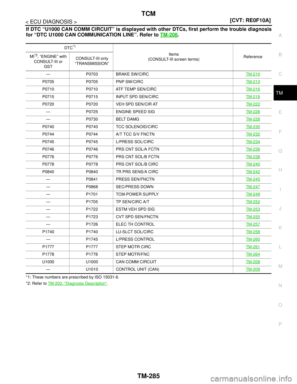
If DTC “U1000 CAN COMM CIRCUIT” is displayed with other DTCs, first perform the trouble diagnosis
for “DTC U1000 CAN COMMUNICATION LINE”. Refer to TM-208
.
*1: These numbers are prescribed by ISO 15031-6.
*2: Refer to TM-202, "
Diagnosis Description". DTC
*1
Items
(CONSULT-III screen terms)Reference MI*2, “ENGINE” with
CONSULT-III or
GSTCONSULT-III only
“TRANSMISSION”
— P0703 BRAKE SW/CIRCTM-210
P0705 P0705 PNP SW/CIRCTM-213
P0710 P0710 ATF TEMP SEN/CIRCTM-216
P0715 P0715 INPUT SPD SEN/CIRCTM-218
P0720 P0720 VEH SPD SEN/CIR ATTM-222
— P0725 ENGINE SPEED SIGTM-226
— P0730 BELT DAMGTM-228
P0740 P0740 TCC SOLENOID/CIRCTM-230
P0744 P0744 A/T TCC S/V FNCTNTM-232
P0745 P0745 L/PRESS SOL/CIRCTM-234
P0746 P0746 PRS CNT SOL/A FCTNTM-236
P0776 P0776 PRS CNT SOL/B FCTNTM-238
P0778 P0778 PRS CNT SOL/B CIRCTM-240
P0840 P0840 TR PRS SENS/A CIRCTM-242
— P0841 PRESS SEN/FNCTNTM-245
— P0868 SEC/PRESS DOWNTM-247
— P1701 TCM-POWER SUPPLYTM-249
— P1705 TP SEN/CIRC A/TTM-252
— P1722 ESTM VEH SPD SIGTM-253
— P1723 CVT SPD SEN/FNCTNTM-255
— P1726 ELEC TH CONTROLTM-257
P1740 P1740 LU-SLCT SOL/CIRCTM-258
— P1745 L/PRESS CONTROLTM-260
P1777 P1777 STEP MOTR CIRCTM-261
P1778 P1778 STEP MOTR/FNCTM-264
U1000 U1000 CAN COMM CIRCUITTM-208
— U1010 CONTROL UNIT (CAN)TM-209
Page 4771 of 5121
TM-298
< PRECAUTION >[CVT: RE0F10A]
PRECAUTIONS
Precaution for Procedure without Cowl Top Cover
INFOID:0000000003901480
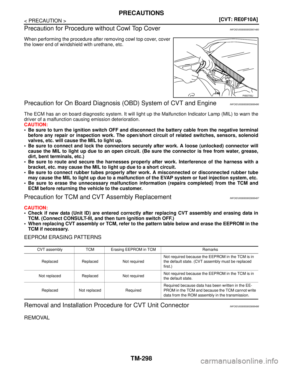
When performing the procedure after removing cowl top cover, cover
the lower end of windshield with urethane, etc.
Precaution for On Board Diagnosis (OBD) System of CVT and EngineINFOID:0000000003806496
The ECM has an on board diagnostic system. It will light up the Malfunction Indicator Lamp (MIL) to warn the
driver of a malfunction causing emission deterioration.
CAUTION:
Be sure to turn the ignition switch OFF and disconnect the battery cable from the negative terminal
before any repair or inspection work. The open/short circuit of related switches, sensors, solenoid
valves, etc. will cause the MIL to light up.
Be sure to connect and lock the connectors securely after work. A loose (unlocked) connector will
cause the MIL to light up due to an open circuit. (Be sure the connector is free from water, grease,
dirt, bent terminals, etc.)
Be sure to route and secure the harnesses properly after work. Interference of the harness with a
bracket, etc. may cause the MIL to light up due to a short circuit.
Be sure to connect rubber tubes properly after work. A misconnected or disconnected rubber tube
may cause the MIL to light up due to a malfunction of the EVAP system or fuel injection system, etc.
Be sure to erase the unnecessary malfunction information (repairs completed) from the TCM and
ECM before returning the vehicle to the customer.
Precaution for TCM and CVT Assembly ReplacementINFOID:0000000003806497
CAUTION:
Check if new data (Unit ID) are entered correctly after replacing CVT assembly and erasing data in
TCM. (Connect CONSULT-III, and then turn ignition switch OFF.)
When replacing CVT assembly or TCM, refer to the pattern table below and erase the EEPROM in the
TCM if necessary.
EEPROM ERASING PATTERNS
Removal and Installation Procedure for CVT Unit ConnectorINFOID:0000000003806498
REMOVAL
PIIB3706J
CVT assembly TCM Erasing EEPROM in TCM Remarks
Replaced Replaced Not requiredNot required because the EEPROM in the TCM is in
the default state. (CVT assembly must be replaced
first.)
Not replaced Replaced Not requiredNot required because the EEPROM in the TCM is in
the default state.
Replaced Not replaced RequiredRequired because data has been written in the EE-
PROM in the TCM and because the TCM cannot write
data from the ROM assembly in the transmission.
Page 4772 of 5121
PRECAUTIONS
TM-299
< PRECAUTION >[CVT: RE0F10A]
C
E
F
G
H
I
J
K
L
MA
B
TM
N
O
P
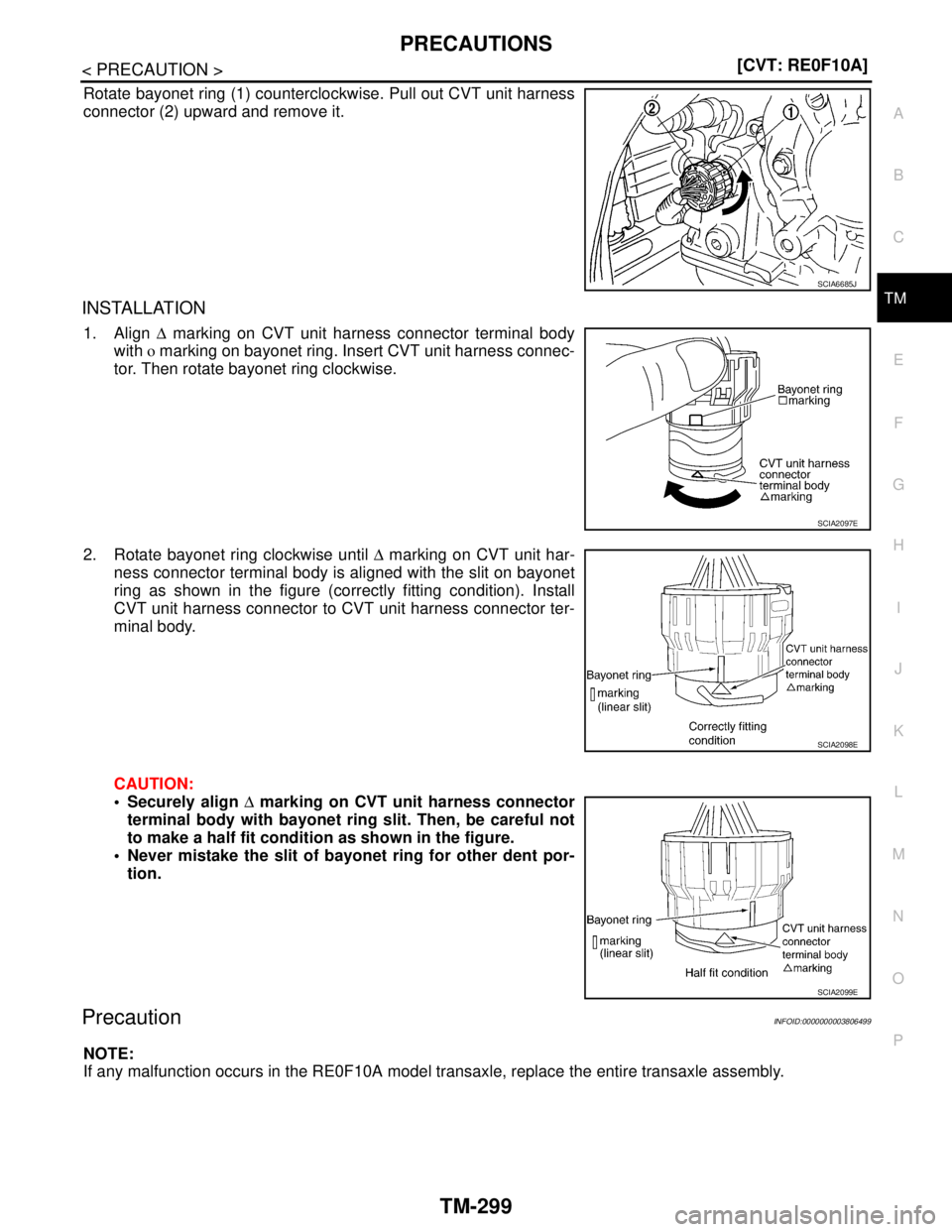
Rotate bayonet ring (1) counterclockwise. Pull out CVT unit harness
connector (2) upward and remove it.
INSTALLATION
1. Align ∆ marking on CVT unit harness connector terminal body
with o marking on bayonet ring. Insert CVT unit harness connec-
tor. Then rotate bayonet ring clockwise.
2. Rotate bayonet ring clockwise until ∆ marking on CVT unit har-
ness connector terminal body is aligned with the slit on bayonet
ring as shown in the figure (correctly fitting condition). Install
CVT unit harness connector to CVT unit harness connector ter-
minal body.
CAUTION:
Securely align ∆ marking on CVT unit harness connector
terminal body with bayonet ring slit. Then, be careful not
to make a half fit condition as shown in the figure.
Never mistake the slit of bayonet ring for other dent por-
tion.
PrecautionINFOID:0000000003806499
NOTE:
If any malfunction occurs in the RE0F10A model transaxle, replace the entire transaxle assembly.
SCIA6685J
SCIA2097E
SCIA2098E
SCIA2099E