2008 NISSAN TEANA ECU
[x] Cancel search: ECUPage 4777 of 5121

TM-304
< ON-VEHICLE MAINTENANCE >[CVT: RE0F10A]
CVT FLUID
ON-VEHICLE MAINTENANCE
CVT FLUID
InspectionINFOID:0000000003806504
CHECKING CVT FLUID
The fluid level should be checked with the fluid warmed up to 50 to 80°C (122 to 176°F). The fluid level check
procedure is as follows:
1. Check for fluid leakage.
2. With the engine warmed up, drive the vehicle in an urban area.
When ambient temperature is 20°C (68°F), it takes about 10
minutes for the CVT fluid to warm up to 50 to 80°C (122 to
176°F).
3. Park the vehicle on a level surface.
4. Apply parking brake firmly.
5. With engine at idle, while depressing brake pedal, move shift
selector throughout the entire shift range.
6. Pull out the CVT fluid level gauge from the CVT fluid charging
pipe after pressing the tab on the CVT fluid level gauge to
release the lock.
7. Wipe fluid off the CVT fluid level gauge. Insert the CVT fluid
level gauge rotating 180° from the originally installed position,
then securely push the CVT fluid level gauge until it meets the
top end of the CVT fluid charging pipe.
CAUTION:
When wiping away the CVT fluid level gauge, always use
lint-free paper, not a cloth rag.
8. Place the selector lever in “P” or “N” and check that the fluid
level is within the specified range.
CAUTION:
When reinstalling CVT fluid level gauge, insert it into the
CVT fluid charging pipe and rotate it to the original installa-
tion position until securely locked.
CVT FLUID CONDITION
SMA146B
SCIA1933E
SCIA1931E
SCIA1932E
Page 4779 of 5121

TM-306
< ON-VEHICLE MAINTENANCE >[CVT: RE0F10A]
STALL TEST
STALL TEST
Inspection and JudgmentINFOID:0000000003806506
INSPECTION
1. Inspect the amount of engine oil. Replenish the engine oil if necessary.
2. Drive for about 10 minutes to warm up the vehicle so that the
CVT fluid temperature is 50 to 80°C (122 to 176°F). Inspect the
amount of CVT fluid. Replenish if necessary.
3. Securely engage the parking brake so that the tires do not turn.
4. Install a tachometer where it can be seen by driver during test.
NOTE:
It is good practice to mark the point of specified engine rpm on
indicator.
5. Start engine, apply foot brake, and place selector lever in “D”
position.
6. While holding down the foot brake, gradually press down the
accelerator pedal.
7. Quickly read off the stall speed, and then quickly remove your
foot from the accelerator pedal.
CAUTION:
Never hold down the accelerator pedal for more than 5 sec-
onds during this test.
8. Move the selector lever to the “N” position.
9. Cool down the CVT fluid.
CAUTION:
Run the engine at idle for at least 1 minute.
10. Repeat steps 6 through 9 with selector lever in “R” position.
JUDGMENT
SAT647B
SCIA7463E
Stall speed : Refer to TM-337, "Stall Speed".
SAT514G
Selector lever position
Expected problem location
“D” “R”
Stall rotation HOForward clutch
O H Reverse brake
L L Engine and torque converter one-way clutch
HH Line pressure low
Primary pulley
Secondary pulley
Steel belt
Page 4781 of 5121

TM-308
< ON-VEHICLE MAINTENANCE >[CVT: RE0F10A]
LINE PRESSURE TEST
LINE PRESSURE TEST
Inspection and JudgmentINFOID:0000000003806507
INSPECTION
Line Pressure Test Procedure
1. Inspect the amount of engine oil and replenish if necessary.
2. Drive the car for about 10 minutes to warm it up so that the CVT fluid reaches in the range of 50 to 80°C
(122 to 176°F), then inspect the amount of CVT fluid and replenish if necessary.
NOTE:
The CVT fluid temperature rises in the range of 50 to 80°C (122 to 176°F) during 10 minutes of driv-
ing.
3. After warming up CVT, remove the oil pressure detection plug
and install the joint pipe adapter (SST: KV31103600), adapter
(SST: 25055000), oil pressure gauge set (commercial service
tool).
CAUTION:
When using the oil pressure gauge, be sure to use the O-
ring attached to the oil pressure detection plug.
4. Securely engage the parking brake so that the tires do not turn.
5. Start the engine, and then measure the line pressure at both idle
and the stall speed.
CAUTION:
Keep the brake pedal pressed all the way down during
measurement.
When measuring the line pressure at the stall speed, refer
to TM-306, "
Inspection and Judgment".
6. After the measurements are complete, install the oil pressure
detection plug and tighten to the specified torque below.
CAUTION:
Never reuse O-ring.
Apply CVT fluid to O-ring.
JUDGMENT
JPDIA0739GB
SCIA7463E
Line pressure : Refer to TM-337, "Line Pressure".
: 7.5 N·m (0.77 kg-m, 66 in-lb)
SAT493G
Page 4819 of 5121

VTL-8
< PRECAUTION >[WITHOUT 7 INCH DISPLAY]
PRECAUTIONS
Precaution for Procedure without Cowl Top Cover
INFOID:0000000003802519
When performing the procedure after removing cowl top cover, cover
the lower end of windshield with urethane, etc.
Precautions For Xenon Headlamp ServiceINFOID:0000000003802520
WARNING:
Comply with the following warnings to prevent any serious accident.
Disconnect the battery cable (negative terminal) or the power supply fuse before installing, remov-
ing, or touching the xenon headlamp (bulb included). The xenon headlamp contains high-voltage
generated parts.
Never work with wet hands.
Check the xenon headlamp ON-OFF status after assembling it to the vehicle. Never turn the xenon
headlamp ON in other conditions. Connect the power supply to the vehicle-side connector.
(Turning it ON outside the lamp case may cause fire or visual impairments.)
Never touch the bulb glass immediately after turning it OFF. It is extremely hot.
CAUTION:
Comply with the following cautions to prevent any error and malfunction.
Install the xenon bulb securely. (Insufficient bulb socket installation may melt the bulb, the connec-
tor, the housing, etc. by high-voltage leakage or corona discharge.)
Never perform HID circuit inspection with a tester.
Never touch the xenon bulb glass with hands. Never put oil and grease on it.
Dispose of the used xenon bulb after packing it in thick vinyl without breaking it.
Never wipe out dirt and contamination with organic solvent (thinner, gasoline, etc.).
Working with HFC-134a (R-134a)INFOID:0000000003802521
CAUTION:
CFC-12 (R-12) refrigerant and HFC-134a (R-134a) refrigerant are not compatible. These refrigerants
must never be mixed, even in the smallest amounts. Compressor malfunction is likely occur if the
refrigerants are mixed.
Use only specified lubricant for the HFC-134a (R-134a) A/C system and HFC-134a (R-134a) compo-
nents. Compressor malfunction is likely to occur if lubricant other than that specified is used.
The specified HFC-134a (R-134a) lubricant rapidly absorbs moisture from the atmosphere. The fol-
lowing handling precautions must be observed:
- Cap (seal) immediately the component to minimize the entry of moisture from the atmosphere when
removing refrigerant components from a vehicle.
- Never remove the caps (unseal) until just before connecting the components when installing refrig-
erant components to a vehicle. Connect all refrigerant loop components as quickly as possible to
minimize the entry of moisture into system.
- Use only the specified lubricant from a sealed container. Reseal immediately containers of lubricant.
Lubricant becomes moisture saturated and should not be used without proper sealing.
- Never allow lubricant (NISSAN A/C System Oil Type S) to come in contact with styrene foam parts.
Damage may result.
General Refrigerant PrecautionINFOID:0000000003802522
WARNING:
Never breath A/C refrigerant and lubricant vapor or mist. Exposure may irritate eyes, nose and
throat. Use only approved recovery/recycling equipment to discharge HFC-134a (R-134a) refrigerant.
PIIB3706J
Page 4876 of 5121

PRECAUTIONS
VTL-65
< PRECAUTION >[WITH 7 INCH DISPLAY]
C
D
E
F
G
H
J
K
L
MA
B
VTL
N
O
P
Precaution for Procedure without Cowl Top CoverINFOID:0000000003894447
When performing the procedure after removing cowl top cover, cover
the lower end of windshield with urethane, etc.
Precautions For Xenon Headlamp ServiceINFOID:0000000003894448
WARNING:
Comply with the following warnings to prevent any serious accident.
Disconnect the battery cable (negative terminal) or the power supply fuse before installing, remov-
ing, or touching the xenon headlamp (bulb included). The xenon headlamp contains high-voltage
generated parts.
Never work with wet hands.
Check the xenon headlamp ON-OFF status after assembling it to the vehicle. Never turn the xenon
headlamp ON in other conditions. Connect the power supply to the vehicle-side connector.
(Turning it ON outside the lamp case may cause fire or visual impairments.)
Never touch the bulb glass immediately after turning it OFF. It is extremely hot.
CAUTION:
Comply with the following cautions to prevent any error and malfunction.
Install the xenon bulb securely. (Insufficient bulb socket installation may melt the bulb, the connec-
tor, the housing, etc. by high-voltage leakage or corona discharge.)
Never perform HID circuit inspection with a tester.
Never touch the xenon bulb glass with hands. Never put oil and grease on it.
Dispose of the used xenon bulb after packing it in thick vinyl without breaking it.
Never wipe out dirt and contamination with organic solvent (thinner, gasoline, etc.).
Working with HFC-134a (R-134a)INFOID:0000000003894449
CAUTION:
CFC-12 (R-12) refrigerant and HFC-134a (R-134a) refrigerant are not compatible. These refrigerants
must never be mixed, even in the smallest amounts. Compressor malfunction is likely occur if the
refrigerants are mixed.
Use only specified lubricant for the HFC-134a (R-134a) A/C system and HFC-134a (R-134a) compo-
nents. Compressor malfunction is likely to occur if lubricant other than that specified is used.
The specified HFC-134a (R-134a) lubricant rapidly absorbs moisture from the atmosphere. The fol-
lowing handling precautions must be observed:
- Cap (seal) immediately the component to minimize the entry of moisture from the atmosphere when
removing refrigerant components from a vehicle.
- Never remove the caps (unseal) until just before connecting the components when installing refrig-
erant components to a vehicle. Connect all refrigerant loop components as quickly as possible to
minimize the entry of moisture into system.
- Use only the specified lubricant from a sealed container. Reseal immediately containers of lubricant.
Lubricant becomes moisture saturated and should not be used without proper sealing.
- Never allow lubricant (NISSAN A/C System Oil Type S) to come in contact with styrene foam parts.
Damage may result.
General Refrigerant PrecautionINFOID:0000000003894450
WARNING:
Never breath A/C refrigerant and lubricant vapor or mist. Exposure may irritate eyes, nose and
throat. Use only approved recovery/recycling equipment to discharge HFC-134a (R-134a) refrigerant.
PIIB3706J
Page 4931 of 5121
WCS
WCS-1
DRIVER INFORMATION & MULTIMEDIA
C
DE
F
G H
I
J
K L
M B
SECTION WCS
A
O P
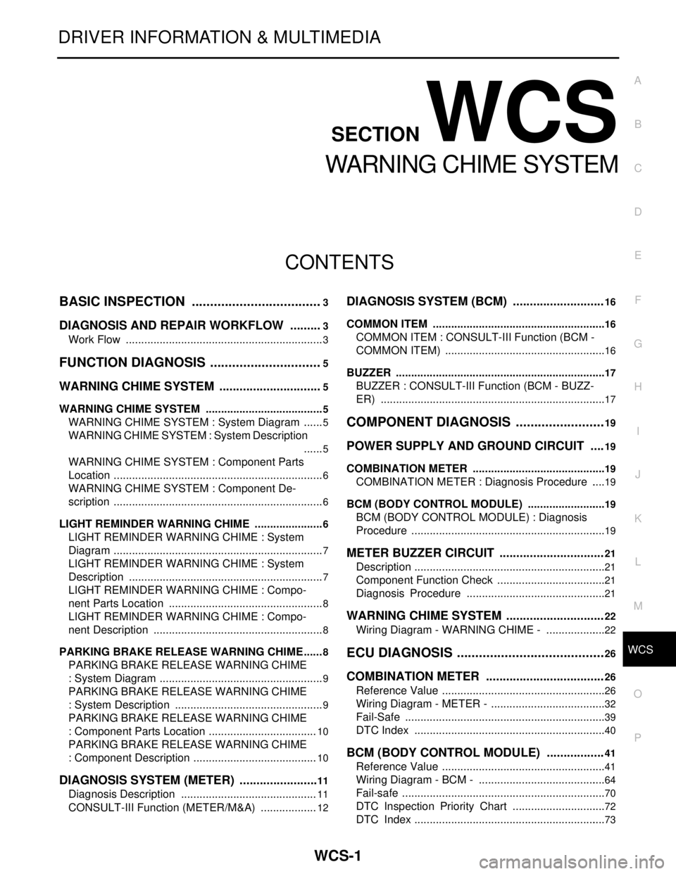
CONTENTS
WARNING CHIME SYSTEM
BASIC INSPECTION ....... .............................3
DIAGNOSIS AND REPAIR WORKFLOW ..... .....3
Work Flow ........................................................... ......3
FUNCTION DIAGNOSIS ...............................5
WARNING CHIME SYSTEM .......................... .....5
WARNING CHIME SYSTEM .......................................5
WARNING CHIME SYSTEM : System Diagram . ......5
WARNING CHIME SYSTEM : System Description
......
5
WARNING CHIME SYSTEM : Component Parts
Location ............................................................... ......
6
WARNING CHIME SYSTEM : Component De-
scription .....................................................................
6
LIGHT REMINDER WARNING CHIME ................. ......6
LIGHT REMINDER WARNING CHIME : System
Diagram .....................................................................
7
LIGHT REMINDER WARNING CHIME : System
Description ................................................................
7
LIGHT REMINDER WARNING CHIME : Compo-
nent Parts Location ...................................................
8
LIGHT REMINDER WARNING CHIME : Compo-
nent Description ........................................................
8
PARKING BRAKE RELEASE WARNING CHIME ......8
PARKING BRAKE RELEASE WARNING CHIME
: System Diagram ......................................................
9
PARKING BRAKE RELEASE WARNING CHIME
: System Description .................................................
9
PARKING BRAKE RELEASE WARNING CHIME
: Component Parts Location ....................................
10
PARKING BRAKE RELEASE WARNING CHIME
: Component Description .........................................
10
DIAGNOSIS SYSTEM (METER) ........................11
Diagnosis Description ......................................... ....11
CONSULT-III Function (METER/M&A) ...................12
DIAGNOSIS SYSTEM (BCM) ...........................16
COMMON ITEM ..................................................... ....16
COMMON ITEM : CONSULT-III Function (BCM -
COMMON ITEM) .....................................................
16
BUZZER ................................................................. ....17
BUZZER : CONSULT-III Function (BCM - BUZZ-
ER) ..........................................................................
17
COMPONENT DIAGNOSIS .........................19
POWER SUPPLY AND GROUND CIRCUIT ....19
COMBINATION METER ........................................ ....19
COMBINATION METER : Diagnosis Procedure .....19
BCM (BODY CONTROL MODULE) ...................... ....19
BCM (BODY CONTROL MODULE) : Diagnosis
Procedure ............................................................ ....
19
METER BUZZER CIRCUIT ...............................21
Description ...............................................................21
Component Function Check ....................................21
Diagnosis Procedure ..............................................21
WARNING CHIME SYSTEM .............................22
Wiring Diagram - WARNING CHIME - ....................22
ECU DIAGNOSIS .........................................26
COMBINATION METER ...................................26
Reference Value .................................................. ....26
Wiring Diagram - METER - ......................................32
Fail-Safe ..................................................................39
DTC Index ...............................................................40
BCM (BODY CONTROL MODULE) .................41
Reference Value ......................................................41
Wiring Diagram - BCM - ..........................................64
Fail-safe ...................................................................70
DTC Inspection Priority Chart ...............................72
DTC Index ...............................................................73
Page 4946 of 5121
WCS-16
< FUNCTION DIAGNOSIS >
DIAGNOSIS SYSTEM (BCM)
DIAGNOSIS SYSTEM (BCM)
COMMON ITEM
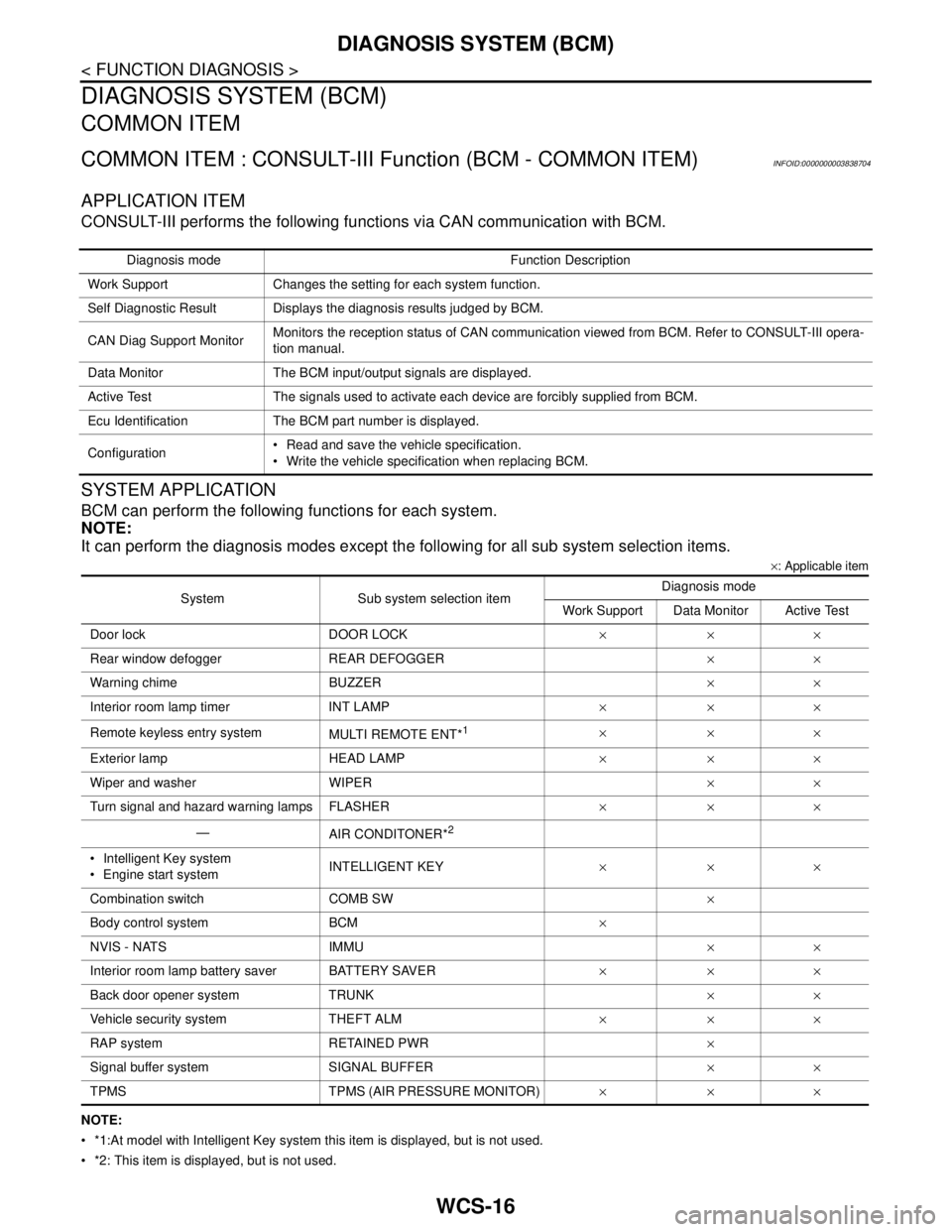
COMMON ITEM : CONSULT-III Function (BCM - COMMON ITEM)INFOID:0000000003838704
APPLICATION ITEM
CONSULT-III performs the following functions via CAN communication with BCM.
SYSTEM APPLICATION
BCM can perform the following functions for each system.
NOTE:
It can perform the diagnosis modes except the following for all sub system selection items.
×: Applicable item
NOTE:
*1:At model with Intelligent Key system this item is displayed, but is not used.
*2: This item is displayed, but is not used. Diagnosis mode Function Description
Work Support Changes the setting for each system function.
Self Diagnostic Result Displays the diagnosis results judged by BCM.
CAN Diag Support MonitorMonitors the reception status of CAN communication viewed from BCM. Refer to CONSULT-III opera-
tion manual.
Data Monitor The BCM input/output signals are displayed.
Active Test The signals used to activate each device are forcibly supplied from BCM.
Ecu Identification The BCM part number is displayed.
Configuration Read and save the vehicle specification.
Write the vehicle specification when replacing BCM.
System Sub system selection itemDiagnosis mode
Work Support Data Monitor Active Test
Door lock DOOR LOCK×××
Rear window defogger REAR DEFOGGER××
Warning chime BUZZER××
Interior room lamp timer INT LAMP×××
Remote keyless entry system
MULTI REMOTE ENT*
1×××
Exterior lamp HEAD LAMP×××
Wiper and washer WIPER××
Turn signal and hazard warning lamps FLASHER×××
—
AIR CONDITONER*
2
Intelligent Key system
Engine start systemINTELLIGENT KEY×××
Combination switch COMB SW×
Body control system BCM×
NVIS - NATS IMMU××
Interior room lamp battery saver BATTERY SAVER×××
Back door opener system TRUNK××
Vehicle security system THEFT ALM×××
RAP system RETAINED PWR×
Signal buffer system SIGNAL BUFFER××
TPMS TPMS (AIR PRESSURE MONITOR)×××
Page 4956 of 5121

WCS-26
< ECU DIAGNOSIS >
COMBINATION METER
ECU DIAGNOSIS
COMBINATION METER
Reference ValueINFOID:0000000003838730
VALUES ON THE DIAGNOSIS TOOL
Monitor Item Condition Value/Status
SPEED METER
[km/h]Ignition switch
ONWhile drivingEquivalent to speedometer reading
NOTE:
655.35 is displayed when the malfunc-
tion signal is received
SPEED OUTPUT
[km/h]Ignition switch
ONWhile drivingEquivalent to speedometer reading
NOTE:
655.35 is displayed when the malfunc-
tion signal is received
ODO OUTPUT
[km/h or mph]Ignition switch
ON—Equivalent to odometer reading in
combination meter
TACHO METER
[rpm]Ignition switch
ONWhile drivingEquivalent to tachometer reading
NOTE:
8191.875 is displayed when the mal-
function signal is received
FUEL METER
[lit]Ignition switch
ON— Values according to fuel level
W TEMP METER
[°C]Ignition switch
ON—Values according to engine coolant
temperature
NOTE:
215 is displayed when the malfunction
signal is input
ABS W/LIgnition switch
ONABS warning lamp ON On
ABS warning lamp OFF Off
VDC/TCS INDIgnition switch
ONVDC OFF indicator lamp ON On
VDC OFF indicator lamp OFF Off
SLIP INDIgnition switch
ONSLIP Indicator lamp ON On
SLIP indicator lamp OFF Off
BRAKE W/LIgnition switch
ONBrake warning lamp ON On
Brake warning lamp OFF Off
DOOR W/LIgnition switch
ONDoor warning ON On
Door warning OFF Off
TRUNK/GLAS-HIgnition switch
ONTrunk warning ON On
Trunk warning OFF Off
HI-BEAM INDIgnition switch
ONHigh-beam indicator lamp ON On
High-beam indicator lamp OFF Off
TURN INDIgnition switch
ONTurn signal indicator lamp ON On
Turn signal indicator lamp OFF Off
FR FOG INDIgnition switch
ONFront fog light indicator lamp ON On
Front fog light indicator lamp OFF Off
RR FOG INDIgnition switch
ONRear fog light indicator lamp ON On
Rear fog light indicator lamp OFF Off
LIGHT IND
Ignition switch
ONTail lamp indicator lamp ON On
Tail lamp indicator lamp OFF Off