2008 NISSAN TEANA washer
[x] Cancel search: washerPage 4638 of 5121
![NISSAN TEANA 2008 Service Manual FLUID COOLER SYSTEM
TM-165
< ON-VEHICLE REPAIR >[CVT: RE0F09B]
C
E
F
G
H
I
J
K
L
MA
B
TM
N
O
P
FLUID COOLER SYSTEM
Exploded ViewINFOID:0000000003849105
Removal and InstallationINFOID:0000000003849106
NISSAN TEANA 2008 Service Manual FLUID COOLER SYSTEM
TM-165
< ON-VEHICLE REPAIR >[CVT: RE0F09B]
C
E
F
G
H
I
J
K
L
MA
B
TM
N
O
P
FLUID COOLER SYSTEM
Exploded ViewINFOID:0000000003849105
Removal and InstallationINFOID:0000000003849106](/manual-img/5/57391/w960_57391-4637.png)
FLUID COOLER SYSTEM
TM-165
< ON-VEHICLE REPAIR >[CVT: RE0F09B]
C
E
F
G
H
I
J
K
L
MA
B
TM
N
O
P
FLUID COOLER SYSTEM
Exploded ViewINFOID:0000000003849105
Removal and InstallationINFOID:0000000003849106
REMOVAL
1. Remove front under cover.
2. Remove fender protector (left side).
3. Remove air duct (inlet). Refer to EM-26, "
Exploded View".
4. Remove fluid cooler hose A and fluid cooler hose B.
5. Remove fluid cooler tube.
INSTALLATION
Note the following, and install in the reverse order of removal.
When installing CVT fluid cooler tube (1) to transaxle assembly:
Contact CVT fluid cooler tube to a boss portion (A) of the transaxle
case.
Tighten the bolt of CVT fluid cooler tube without moving the CVT
fluid cooler tube.
1. Copper washer 2. Fluid cooler tube 3. Hose clamp
4. Fluid cooler hose A 5. Fluid cooler hose B 6. Transaxle assembly
A. To radiator assembly
Refer to GI-4, "
Components" for symbols in the figure.
JPDIA0792GB
JPDIA0628ZZ
Page 4802 of 5121
![NISSAN TEANA 2008 Service Manual FLUID COOLER SYSTEM
TM-329
< ON-VEHICLE REPAIR >[CVT: RE0F10A]
C
E
F
G
H
I
J
K
L
MA
B
TM
N
O
P
FLUID COOLER SYSTEM
Exploded ViewINFOID:0000000003886234
Removal and InstallationINFOID:0000000003886235
NISSAN TEANA 2008 Service Manual FLUID COOLER SYSTEM
TM-329
< ON-VEHICLE REPAIR >[CVT: RE0F10A]
C
E
F
G
H
I
J
K
L
MA
B
TM
N
O
P
FLUID COOLER SYSTEM
Exploded ViewINFOID:0000000003886234
Removal and InstallationINFOID:0000000003886235](/manual-img/5/57391/w960_57391-4801.png)
FLUID COOLER SYSTEM
TM-329
< ON-VEHICLE REPAIR >[CVT: RE0F10A]
C
E
F
G
H
I
J
K
L
MA
B
TM
N
O
P
FLUID COOLER SYSTEM
Exploded ViewINFOID:0000000003886234
Removal and InstallationINFOID:0000000003886235
REMOVAL
1. Remove air duct (inlet). Refer to EM-26, "Exploded View".
2. Remove engine under cover. Refer to EXT-28, "
Exploded View".
3. Remove fender protector (left side). Refer to EXT-22, "
FENDER PROTECTOR : Exploded View".
4. Remove fluid cooler hose A and fluid cooler hose B.
5. Remove CVT fluid cooler tube from transaxle assembly.
INSTALLATION
Note the following, and install in the reverse order of removal.
CAUTION:
Never reuse copper washer.
1. Hose clamp 2. Fluid cooler hose A 3. Fluid cooler hose B
4. Copper washer 5. CVT fluid cooler tube 6. CVT fluid cooler tube
7. Transaxle assembly
A. To radiator
: Vehicle front
Refer to GI-4, "
Components" for symbols in the figure.
JPDIA0787GB
Page 4943 of 5121
![NISSAN TEANA 2008 Service Manual WCS
DIAGNOSIS SYSTEM (METER)
WCS-13
< FUNCTION DIAGNOSIS >
C
D
E
F
G
H
I
J
K
L
MB A
O
P
W TEMP METER
[°C] XValue of engine coolant temperature signal is received from ECM via CAN com-
munication.
NO NISSAN TEANA 2008 Service Manual WCS
DIAGNOSIS SYSTEM (METER)
WCS-13
< FUNCTION DIAGNOSIS >
C
D
E
F
G
H
I
J
K
L
MB A
O
P
W TEMP METER
[°C] XValue of engine coolant temperature signal is received from ECM via CAN com-
munication.
NO](/manual-img/5/57391/w960_57391-4942.png)
WCS
DIAGNOSIS SYSTEM (METER)
WCS-13
< FUNCTION DIAGNOSIS >
C
D
E
F
G
H
I
J
K
L
MB A
O
P
W TEMP METER
[°C] XValue of engine coolant temperature signal is received from ECM via CAN com-
munication.
NOTE:
215 is displayed when the malfunction signal is input.
ABS W/L
[On/Off]Status of ABS warning lamp detected from ABS warning lamp signal is received
from ABS actuator and electric unit (control unit) via CAN communication.
VDC/TCS IND
[On/Off]Status of VDC OFF indicator lamp detected from VDC OFF indicator lamp signal
is received from ABS actuator and electric unit (control unit) via CAN communica-
tion.
SLIP IND
[On/Off]Status of SLIP indicator lamp detected from slip indicator lamp signal received
from ABS actuator and electric unit (control unit) via CAN communication.
BRAKE W/L
[On/Off]Status of brake warning lamp detected from brake warning lamp signal is received
from ABS actuator and electric unit (control unit) via CAN communication.
NOTE:
Displays “Off” if the brake warning lamp is illuminated when the valve check starts,
the parking brake switch is turned ON or the brake fluid level switch is turned ON.
DOOR W/L
[On/Off]Status of door warning detected from door switch signal received from BCM via
CAN communication.
TRUNK/GLAS-H
[On/Off]Status of trunk warning detected from trunk switch signal received from BCM via
CAN communication.
HI-BEAM IND
[On/Off]Status of high beam indicator lamp detected from high beam request signal is re-
ceived from BCM via CAN communication.
TURN IND
[On/Off]Status of turn indicator lamp detected from turn indicator signal is received from
BCM via CAN communication.
FR FOG IND
[On/Off]Status of front fog light indicator lamp detected from front fog light request signal
is received from BCM via CAN communication.
RR FOG IND
[On/Off]Status of rear fog light indicator lamp detected from rear fog light request signal is
received from BCM via CAN communication.
LIGHT IND
[On/Off]Status of light indicator lamp detected from position light request signal is received
from BCM via CAN communication.
OIL W/L
[On/Off]Status of oil pressure warning lamp detected from oil pressure switch signal is re-
ceived from BCM via CAN communication.
MIL
[On/Off] Status of malfunction indicator lamp detected from malfunctioning indicator lamp
signal is received from ECM via CAN communication.
CRUISE IND
[On/Off]Status of CRUISE indicator detected from ASCD status signal is received from
ECM via CAN communication.
SPORT IND
[On/Off]Status of SPORT indicator detected from sport mode switch signal is received
from control device.
4WD W/L
[On/Off]This item is displayed, but cannot be monitored.
4WD LOCK IND
[On/Off]This item is displayed, but cannot be monitored.
FUEL W/L
[On/Off]Low-fuel warning lamp status detected by the identified fuel level.
WASHER W/L
[On/Off]This item is displayed, but cannot be monitored.
KEY G/Y W/L
[On/Off]Status of key warning lamp (G/Y) detected from key warning signal is received
from BCM via CAN communication.
AFS OFF IND
[On/Off]This item is displayed, but cannot be monitored.
LCD
[B&P N, B&P I, ID NG, ROTAT, SFT
P, INSRT, BATT, NO KY,OUTKY, LK
WN]Displays status of Intelligent Key system warning detected from meter display sig-
nal is received from BCM via CAN communication.
Display item [Unit]MAIN
SIGNALSDescription
Page 4945 of 5121

WCS
DIAGNOSIS SYSTEM (METER)
WCS-15
< FUNCTION DIAGNOSIS >
C
D
E
F
G
H
I
J
K
L
MB A
O
P
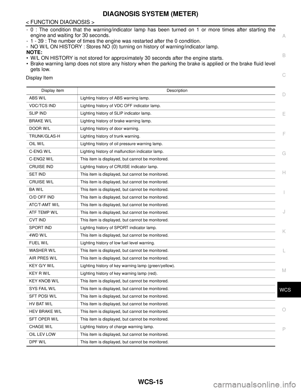
- 0 : The condition that the warning/indicator lamp has been turned on 1 or more times after starting the
engine and waiting for 30 seconds.
- 1 - 39 : The number of times the engine was restarted after the 0 condition.
- NO W/L ON HISTORY : Stores NO (0) turning on history of warning/indicator lamp.
NOTE:
W/L ON HISTORY is not stored for approximately 30 seconds after the engine starts.
Brake warning lamp does not store any history when the parking the brake is applied or the brake fluid level
gets low.
Display Item
Display item Description
ABS W/L Lighting history of ABS warning lamp.
VDC/TCS IND Lighting history of VDC OFF indicator lamp.
SLIP IND Lighting history of SLIP indicator lamp.
BRAKE W/L Lighting history of brake warning lamp.
DOOR W/L Lighting history of door warning.
TRUNK/GLAS-H Lighting history of trunk warning.
OIL W/L Lighting history of oil pressure warning lamp.
C-ENG W/L Lighting history of malfunction indicator lamp.
C-ENG2 W/L This item is displayed, but cannot be monitored.
CRUISE IND Lighting history of CRUISE indicator lamp.
SET IND This item is displayed, but cannot be monitored.
CRUISE W/L This item is displayed, but cannot be monitored.
BA W/L This item is displayed, but cannot be monitored.
O/D OFF IND This item is displayed, but cannot be monitored.
ATC/T-AMT W/L This item is displayed, but cannot be monitored.
ATF TEMP W/L This item is displayed, but cannot be monitored.
CVT IND This item is displayed, but cannot be monitored.
SPORT IND Lighting history of SPORT indicator lamp.
4WD W/L This item is displayed, but cannot be monitored.
FUEL W/L Lighting history of low fuel level warning.
WASHER W/L This item is displayed, but cannot be monitored.
AIR PRES W/L This item is displayed, but cannot be monitored.
KEY G/Y W/L Lighting history of key warning lamp (green/yellow).
KEY R W/L Lighting history of key warning lamp (red).
KEY KNOB W/L This item is displayed, but cannot be monitored.
SYS FAIL W/L This item is displayed, but cannot be monitored.
SFT POSI W/L This item is displayed, but cannot be monitored.
HV BAT W/L This item is displayed, but cannot be monitored.
HEV BRAKE W/L This item is displayed, but cannot be monitored.
SFT OPER W/L This item is displayed, but cannot be monitored.
CHAGE W/L Lighting history of charge warning lamp.
OIL LEV LOW This item is displayed, but cannot be monitored.
DPF W/L This item is displayed, but cannot be monitored.
Page 4946 of 5121

WCS-16
< FUNCTION DIAGNOSIS >
DIAGNOSIS SYSTEM (BCM)
DIAGNOSIS SYSTEM (BCM)
COMMON ITEM
COMMON ITEM : CONSULT-III Function (BCM - COMMON ITEM)INFOID:0000000003838704
APPLICATION ITEM
CONSULT-III performs the following functions via CAN communication with BCM.
SYSTEM APPLICATION
BCM can perform the following functions for each system.
NOTE:
It can perform the diagnosis modes except the following for all sub system selection items.
×: Applicable item
NOTE:
*1:At model with Intelligent Key system this item is displayed, but is not used.
*2: This item is displayed, but is not used. Diagnosis mode Function Description
Work Support Changes the setting for each system function.
Self Diagnostic Result Displays the diagnosis results judged by BCM.
CAN Diag Support MonitorMonitors the reception status of CAN communication viewed from BCM. Refer to CONSULT-III opera-
tion manual.
Data Monitor The BCM input/output signals are displayed.
Active Test The signals used to activate each device are forcibly supplied from BCM.
Ecu Identification The BCM part number is displayed.
Configuration Read and save the vehicle specification.
Write the vehicle specification when replacing BCM.
System Sub system selection itemDiagnosis mode
Work Support Data Monitor Active Test
Door lock DOOR LOCK×××
Rear window defogger REAR DEFOGGER××
Warning chime BUZZER××
Interior room lamp timer INT LAMP×××
Remote keyless entry system
MULTI REMOTE ENT*
1×××
Exterior lamp HEAD LAMP×××
Wiper and washer WIPER××
Turn signal and hazard warning lamps FLASHER×××
—
AIR CONDITONER*
2
Intelligent Key system
Engine start systemINTELLIGENT KEY×××
Combination switch COMB SW×
Body control system BCM×
NVIS - NATS IMMU××
Interior room lamp battery saver BATTERY SAVER×××
Back door opener system TRUNK××
Vehicle security system THEFT ALM×××
RAP system RETAINED PWR×
Signal buffer system SIGNAL BUFFER××
TPMS TPMS (AIR PRESSURE MONITOR)×××
Page 4957 of 5121

WCS
COMBINATION METER
WCS-27
< ECU DIAGNOSIS >
C
D
E
F
G
H
I
J
K
L
MB A
O
P
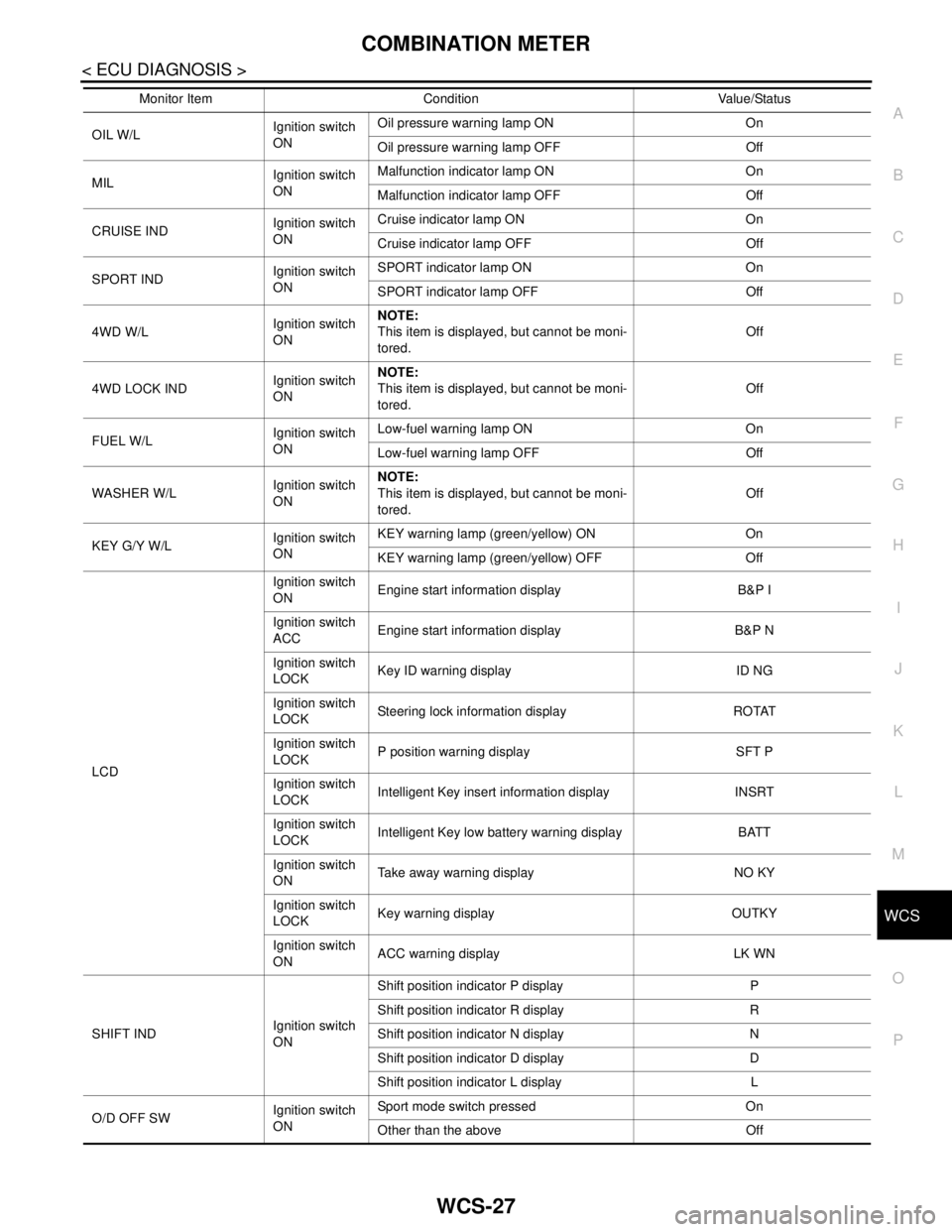
OIL W/L Ignition switch
ONOil pressure warning lamp ON On
Oil pressure warning lamp OFF Off
MILIgnition switch
ONMalfunction indicator lamp ON On
Malfunction indicator lamp OFF Off
CRUISE INDIgnition switch
ONCruise indicator lamp ON On
Cruise indicator lamp OFF Off
SPORT INDIgnition switch
ONSPORT indicator lamp ON On
SPORT indicator lamp OFF Off
4WD W/LIgnition switch
ONNOTE:
This item is displayed, but cannot be moni-
tored.Off
4WD LOCK INDIgnition switch
ONNOTE:
This item is displayed, but cannot be moni-
tored.Off
FUEL W/LIgnition switch
ONLow-fuel warning lamp ON On
Low-fuel warning lamp OFF Off
WASHER W/LIgnition switch
ONNOTE:
This item is displayed, but cannot be moni-
tored.Off
KEY G/Y W/L Ignition switch
ONKEY warning lamp (green/yellow) ON On
KEY warning lamp (green/yellow) OFF Off
LCDIgnition switch
ONEngine start information display B&P I
Ignition switch
ACCEngine start information display B&P N
Ignition switch
LOCKKey ID warning display ID NG
Ignition switch
LOCKSteering lock information display ROTAT
Ignition switch
LOCKP position warning display SFT P
Ignition switch
LOCKIntelligent Key insert information display INSRT
Ignition switch
LOCKIntelligent Key low battery warning display BATT
Ignition switch
ONTake away warning display NO KY
Ignition switch
LOCKKey warning display OUTKY
Ignition switch
ONACC warning display LK WN
SHIFT INDIgnition switch
ONShift position indicator P display P
Shift position indicator R display R
Shift position indicator N display N
Shift position indicator D display D
Shift position indicator L display L
O/D OFF SWIgnition switch
ONSport mode switch pressed On
Other than the above Off Monitor Item Condition Value/Status
Page 4971 of 5121

WCS
BCM (BODY CONTROL MODULE)
WCS-41
< ECU DIAGNOSIS >
C
D
E
F
G
H
I
J
K
L
MB A
O
P
BCM (BODY CONTROL MODULE)
Reference ValueINFOID:0000000003900508
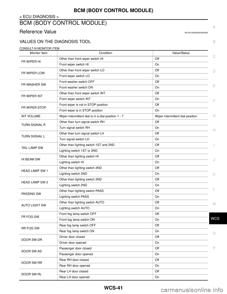
VALUES ON THE DIAGNOSIS TOOL
CONSULT-III MONITOR ITEM
Monitor Item Condition Value/Status
FR WIPER HIOther than front wiper switch HI Off
Front wiper switch HI On
FR WIPER LOWOther than front wiper switch LO Off
Front wiper switch LO On
FR WASHER SWFront washer switch OFF Off
Front washer switch ON On
FR WIPER INTOther than front wiper switch INT Off
Front wiper switch INT On
FR WIPER STOPFront wiper is not in STOP position Off
Front wiper is in STOP position On
INT VOLUME Wiper intermittent dial is in a dial position 1 - 7 Wiper intermittent dial position
TURN SIGNAL ROther than turn signal switch RH Off
Turn signal switch RH On
TURN SIGNAL LOther than turn signal switch LH Off
Turn signal switch LH On
TAIL LAMP SWOther than lighting switch 1ST and 2ND Off
Lighting switch 1ST or 2ND On
HI BEAM SWOther than lighting switch HI Off
Lighting switch HI On
HEAD LAMP SW 1Other than lighting switch 2ND Off
Lighting switch 2ND On
HEAD LAMP SW 2Other than lighting switch 2ND Off
Lighting switch 2ND On
PA S S I N G S WOther than lighting switch PASS Off
Lighting switch PASS On
AUTO LIGHT SWOther than lighting switch AUTO Off
Lighting switch AUTO On
FR FOG SWFront fog lamp switch OFF Off
Front fog lamp switch ON On
RR FOG SWRear fog lamp switch OFF Off
Rear fog lamp switch ON On
DOOR SW-DRDriver door closed Off
Driver door opened On
DOOR SW-ASPassenger door closed Off
Passenger door opened On
DOOR SW-RRRear RH door closed Off
Rear RH door opened On
DOOR SW-RLRear LH door closed Off
Rear LH door opened On
Page 4987 of 5121

WCS
BCM (BODY CONTROL MODULE)
WCS-57
< ECU DIAGNOSIS >
C
D
E
F
G
H
I
J
K
L
MB A
O
P
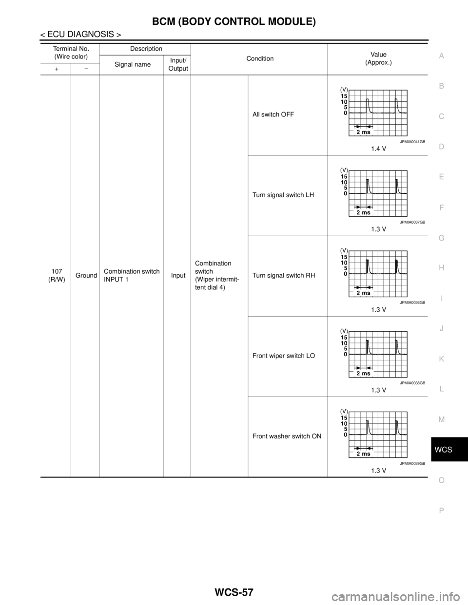
107
(R/W)GroundCombination switch
INPUT 1InputCombination
switch
(Wiper intermit-
tent dial 4)All switch OFF
1.4 V
Turn signal switch LH
1.3 V
Turn signal switch RH
1.3 V
Front wiper switch LO
1.3 V
Front washer switch ON
1.3 V Te r m i n a l N o .
(Wire color)Description
ConditionVa l u e
(Approx.)
Signal nameInput/
Output +–
JPMIA0041GB
JPMIA0037GB
JPMIA0036GB
JPMIA0038GB
JPMIA0039GB