2008 NISSAN TEANA washer
[x] Cancel search: washerPage 4199 of 5121
![NISSAN TEANA 2008 Service Manual SEC-190
< ECU DIAGNOSIS >[INTELLIGENT KEY SYSTEM]
IPDM E/R (INTELLIGENT POWER DISTRIBUTION MODULE ENGINE ROOM)
If No CAN Communication Is Available With BCM
IGNITION RELAY MALFUNCTION DETECTION FUNCTI NISSAN TEANA 2008 Service Manual SEC-190
< ECU DIAGNOSIS >[INTELLIGENT KEY SYSTEM]
IPDM E/R (INTELLIGENT POWER DISTRIBUTION MODULE ENGINE ROOM)
If No CAN Communication Is Available With BCM
IGNITION RELAY MALFUNCTION DETECTION FUNCTI](/manual-img/5/57391/w960_57391-4198.png)
SEC-190
< ECU DIAGNOSIS >[INTELLIGENT KEY SYSTEM]
IPDM E/R (INTELLIGENT POWER DISTRIBUTION MODULE ENGINE ROOM)
If No CAN Communication Is Available With BCM
IGNITION RELAY MALFUNCTION DETECTION FUNCTION
IPDM E/R monitors the voltage at the contact circuit and excitation coil circuit of the ignition relay inside it.
IPDM E/R judges the ignition relay error if the voltage differs between the contact circuit and the excitation
coil circuit.
If the ignition relay cannot turn OFF due to contact seizure, it activates the tail lamp relay for 10 minutes to
alert the user to the ignition relay malfunction when the ignition switch is turned OFF.
FRONT WIPER CONTROL
IPDM E/R detects front wiper stop position by a front wiper auto stop signal.
When a front wiper auto stop signal is in the conditions listed below, IPDM E/R stops power supply to wiper
after repeating a front wiper 10 seconds activation and 20 seconds stop five times.
Control part Fail-safe operation
Cooling fan Turns ON the cooling fan relay-2 and the cooling fan relay-3 when ignition switch is
turned ON (Cooling fan operates at HI)
Turns OFF the cooling fan relay-1, the cooling fan relay-2 and the cooling fan relay-3
when the ignition switch is turned OFF (Cooling fan does not operate)
A/C compressor A/C relay OFF
Alternator Outputs the power generation command signal (PWM signal) 0%
Control part Fail-safe operation
Headlamp Turns ON the headlamp low relay when the ignition switch is turned ON
Turns OFF the headlamp low relay when the ignition switch is turned OFF
Headlamp high relay OFF
Parking lamps
License plate lamps
Illuminations
Tail lamps Turns ON the tail lamp relay when the ignition switch is turned ON
Turns OFF the tail lamp relay when the ignition switch is turned OFF
Front wiper The status just before activation of fail-safe control is maintained until the ignition
switch is turned OFF while the front wiper is operating at LO or HI speed.
The wiper is operated at LO speed until the ignition switch is turned OFF if the fail-
safe control is activated while the front wiper is set in the INT mode and the front wiper
motor is operating.
Front fog lamps Front fog lamp relay OFF
Horn Horn OFF
Ignition relay The status just before activation of fail-safe is maintained.
Starter motor Starter control relay OFF
Steering lock unit Steering lock relay OFF
Headlamp washer relay Headlamp washer relay OFF
Voltage judgment
IPDM E/R judgment Operation
Ignition relay contact sideIgnition relay excitation coil
side
ON ON Ignition relay ON normal —
OFF OFF Ignition relay OFF normal —
ON OFF Ignition relay ON stuck Detects DTC “B2098: IGN RELAY ON”
Turns ON the tail lamp relay for 10 min-
utes
OFF ON Ignition relay OFF stuck Detects DTC “B2099: IGN RELAY OFF”
Page 4397 of 5121
POWER STEERING FLUID
ST-7
< ON-VEHICLE MAINTENANCE >
C
D
E
F
H
I
J
K
L
MA
B
ST
N
O
P
ON-VEHICLE MAINTENANCE
POWER STEERING FLUID
InspectionINFOID:0000000003826225
FLUID LEVEL
1. Check fluid level with engine stopped.
2. Ensure that fluid level is between MIN and MAX.
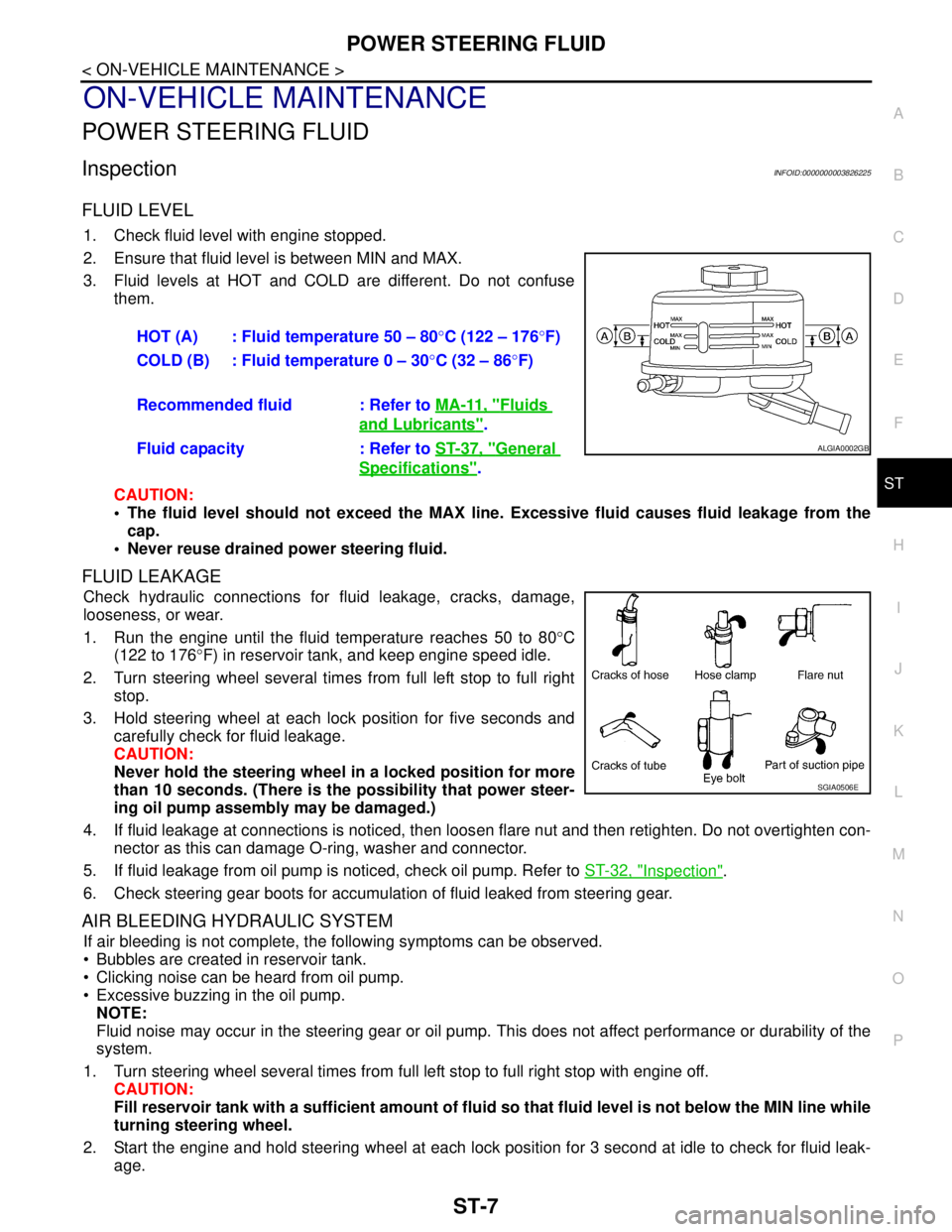
3. Fluid levels at HOT and COLD are different. Do not confuse
them.
CAUTION:
The fluid level should not exceed the MAX line. Excessive fluid causes fluid leakage from the
cap.
Never reuse drained power steering fluid.
FLUID LEAKAGE
Check hydraulic connections for fluid leakage, cracks, damage,
looseness, or wear.
1. Run the engine until the fluid temperature reaches 50 to 80°C
(122 to 176°F) in reservoir tank, and keep engine speed idle.
2. Turn steering wheel several times from full left stop to full right
stop.
3. Hold steering wheel at each lock position for five seconds and
carefully check for fluid leakage.
CAUTION:
Never hold the steering wheel in a locked position for more
than 10 seconds. (There is the possibility that power steer-
ing oil pump assembly may be damaged.)
4. If fluid leakage at connections is noticed, then loosen flare nut and then retighten. Do not overtighten con-
nector as this can damage O-ring, washer and connector.
5. If fluid leakage from oil pump is noticed, check oil pump. Refer to ST-32, "
Inspection".
6. Check steering gear boots for accumulation of fluid leaked from steering gear.
AIR BLEEDING HYDRAULIC SYSTEM
If air bleeding is not complete, the following symptoms can be observed.
Bubbles are created in reservoir tank.
Clicking noise can be heard from oil pump.
Excessive buzzing in the oil pump.
NOTE:
Fluid noise may occur in the steering gear or oil pump. This does not affect performance or durability of the
system.
1. Turn steering wheel several times from full left stop to full right stop with engine off.
CAUTION:
Fill reservoir tank with a sufficient amount of fluid so that fluid level is not below the MIN line while
turning steering wheel.
2. Start the engine and hold steering wheel at each lock position for 3 second at idle to check for fluid leak-
age.HOT (A) : Fluid temperature 50 – 80°C (122 – 176°F)
COLD (B) : Fluid temperature 0 – 30°C (32 – 86°F)
Recommended fluid : Refer to MA-11, "
Fluids
and Lubricants".
Fluid capacity : Refer to ST-37, "
General
Specifications".
ALGIA0002GB
SGIA0506E
Page 4419 of 5121
POWER STEERING OIL PUMP
ST-29
< ON-VEHICLE REPAIR >
C
D
E
F
H
I
J
K
L
MA
B
ST
N
O
P
Removal and InstallationINFOID:0000000003806327
REMOVAL
1. Drain power steering fluid from reservoir tank.
2. Remove front tires.
3. Remove splash guard. Refer to EXT-22, "
FENDER PROTECTOR : Exploded View".
4. Loosen drive belt. Refer to EM-12, "
Removal and Installation".
5. Remove drive belt from oil pump pulley.
6. Remove copper washers and eye bolt (drain fluid from their pipings).
7. Remove suction hose (drain fluid from their pipings).
8. Remove oil pump mounting bolts, and then remove oil pump.
CAUTION:
Never damage drive shaft boot.
INSTALLATION
Note the following, and install in the reverse order of removal.
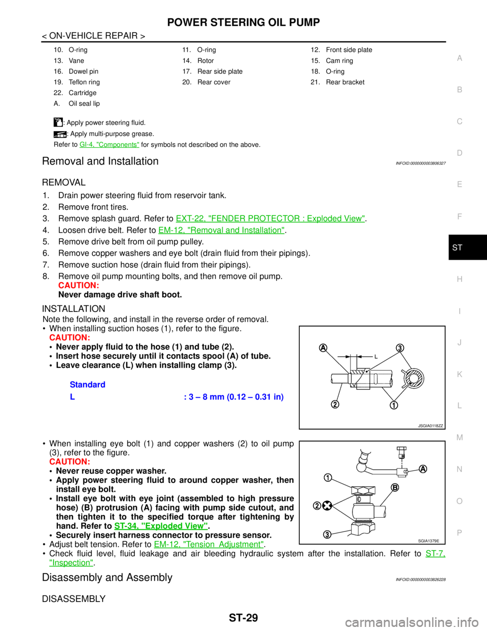
When installing suction hoses (1), refer to the figure.
CAUTION:
Never apply fluid to the hose (1) and tube (2).
Insert hose securely until it contacts spool (A) of tube.
Leave clearance (L) when installing clamp (3).
When installing eye bolt (1) and copper washers (2) to oil pump
(3), refer to the figure.
CAUTION:
Never reuse copper washer.
Apply power steering fluid to around copper washer, then
install eye bolt.
Install eye bolt with eye joint (assembled to high pressure
hose) (B) protrusion (A) facing with pump side cutout, and
then tighten it to the specified torque after tightening by
hand. Refer to ST-34, "
Exploded View".
Securely insert harness connector to pressure sensor.
Adjust belt tension. Refer to EM-12, "
TensionAdjustment".
Check fluid level, fluid leakage and air bleeding hydraulic system after the installation. Refer to ST-7,
"Inspection".
Disassembly and AssemblyINFOID:0000000003826228
DISASSEMBLY
10. O-ring 11. O-ring 12. Front side plate
13. Vane 14. Rotor 15. Cam ring
16. Dowel pin 17. Rear side plate 18. O-ring
19. Teflon ring 20. Rear cover 21. Rear bracket
22. Cartridge
A. Oil seal lip
: Apply power steering fluid.
: Apply multi-purpose grease.
Refer to GI-4, "
Components" for symbols not described on the above.
Standard
L : 3 – 8 mm (0.12 – 0.31 in)
JSGIA0118ZZ
SGIA1379E
Page 4422 of 5121
ST-32
< ON-VEHICLE REPAIR >
POWER STEERING OIL PUMP
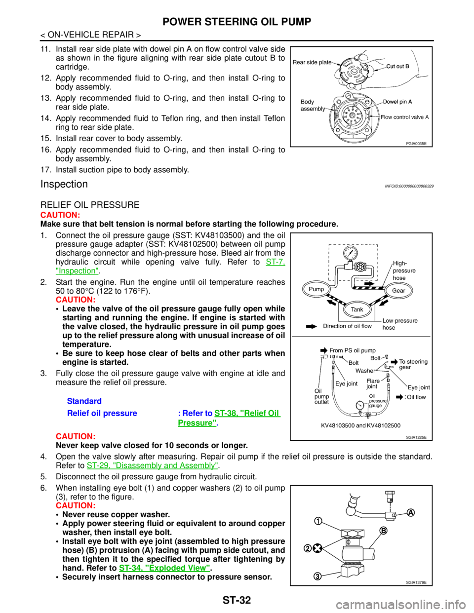
11. Install rear side plate with dowel pin A on flow control valve side
as shown in the figure aligning with rear side plate cutout B to
cartridge.
12. Apply recommended fluid to O-ring, and then install O-ring to
body assembly.
13. Apply recommended fluid to O-ring, and then install O-ring to
rear side plate.
14. Apply recommended fluid to Teflon ring, and then install Teflon
ring to rear side plate.
15. Install rear cover to body assembly.
16. Apply recommended fluid to O-ring, and then install O-ring to
body assembly.
17. Install suction pipe to body assembly.
InspectionINFOID:0000000003806329
RELIEF OIL PRESSURE
CAUTION:
Make sure that belt tension is normal before starting the following procedure.
1. Connect the oil pressure gauge (SST: KV48103500) and the oil
pressure gauge adapter (SST: KV48102500) between oil pump
discharge connector and high-pressure hose. Bleed air from the
hydraulic circuit while opening valve fully. Refer to ST-7,
"Inspection".
2. Start the engine. Run the engine until oil temperature reaches
50 to 80°C (122 to 176°F).
CAUTION:
Leave the valve of the oil pressure gauge fully open while
starting and running the engine. If engine is started with
the valve closed, the hydraulic pressure in oil pump goes
up to the relief pressure along with unusual increase of oil
temperature.
Be sure to keep hose clear of belts and other parts when
engine is started.
3. Fully close the oil pressure gauge valve with engine at idle and
measure the relief oil pressure.
CAUTION:
Never keep valve closed for 10 seconds or longer.
4. Open the valve slowly after measuring. Repair oil pump if the relief oil pressure is outside the standard.
Refer to ST-29, "
Disassembly and Assembly".
5. Disconnect the oil pressure gauge from hydraulic circuit.
6. When installing eye bolt (1) and copper washers (2) to oil pump
(3), refer to the figure.
CAUTION:
Never reuse copper washer.
Apply power steering fluid or equivalent to around copper
washer, then install eye bolt.
Install eye bolt with eye joint (assembled to high pressure
hose) (B) protrusion (A) facing with pump side cutout, and
then tighten it to the specified torque after tightening by
hand. Refer to ST-34, "
Exploded View".
Securely insert harness connector to pressure sensor.
PGIA0035E
Standard
Relief oil pressure : Refer to ST-38, "
Relief Oil
Pressure".
SGIA1225E
SGIA1379E
Page 4424 of 5121
ST-34
< ON-VEHICLE REPAIR >
HYDRAULIC LINE
HYDRAULIC LINE
Exploded ViewINFOID:0000000003806330
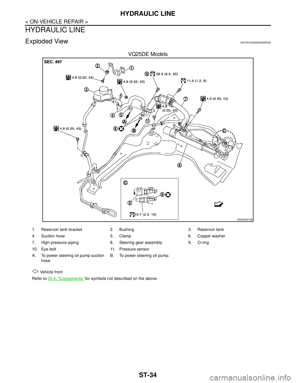
VQ25DE Models
JSGIA0401GB
1. Reservoir tank bracket 2. Bushing 3. Reservoir tank
4. Suction hose 5. Clamp 6. Copper washer
7. High pressure piping 8. Steering gear assembly 9. O-ring
10. Eye bolt 11. Pressure sensor
A. To power steering oil pump suction
hose.B. To power steering oil pump.
: Vehicle front
Refer to GI-4, "
Components" for symbols not described on the above.
Page 4425 of 5121
HYDRAULIC LINE
ST-35
< ON-VEHICLE REPAIR >
C
D
E
F
H
I
J
K
L
MA
B
ST
N
O
P
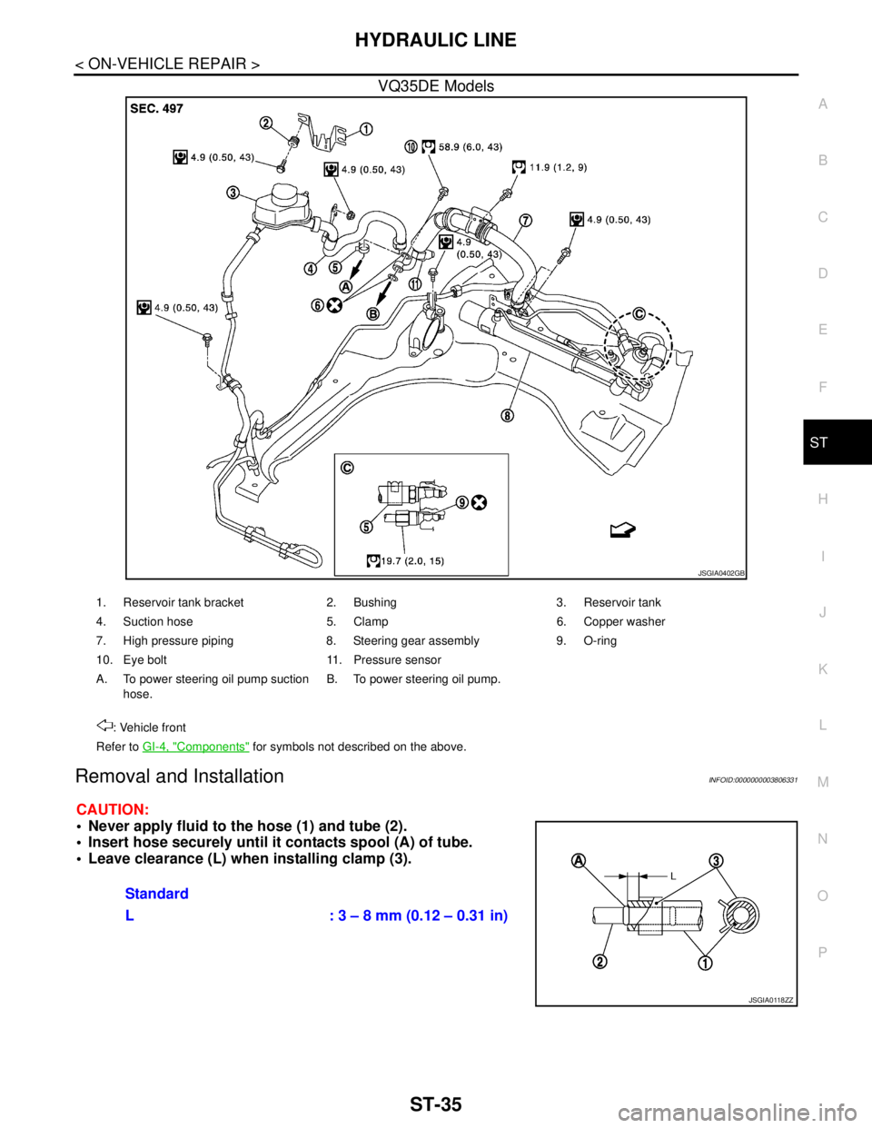
VQ35DE Models
Removal and InstallationINFOID:0000000003806331
CAUTION:
Never apply fluid to the hose (1) and tube (2).
Insert hose securely until it contacts spool (A) of tube.
Leave clearance (L) when installing clamp (3).
JSGIA0402GB
1. Reservoir tank bracket 2. Bushing 3. Reservoir tank
4. Suction hose 5. Clamp 6. Copper washer
7. High pressure piping 8. Steering gear assembly 9. O-ring
10. Eye bolt 11. Pressure sensor
A. To power steering oil pump suction
hose.B. To power steering oil pump.
: Vehicle front
Refer to GI-4, "
Components" for symbols not described on the above.
Standard
L : 3 – 8 mm (0.12 – 0.31 in)
JSGIA0118ZZ
Page 4426 of 5121
ST-36
< ON-VEHICLE REPAIR >
HYDRAULIC LINE
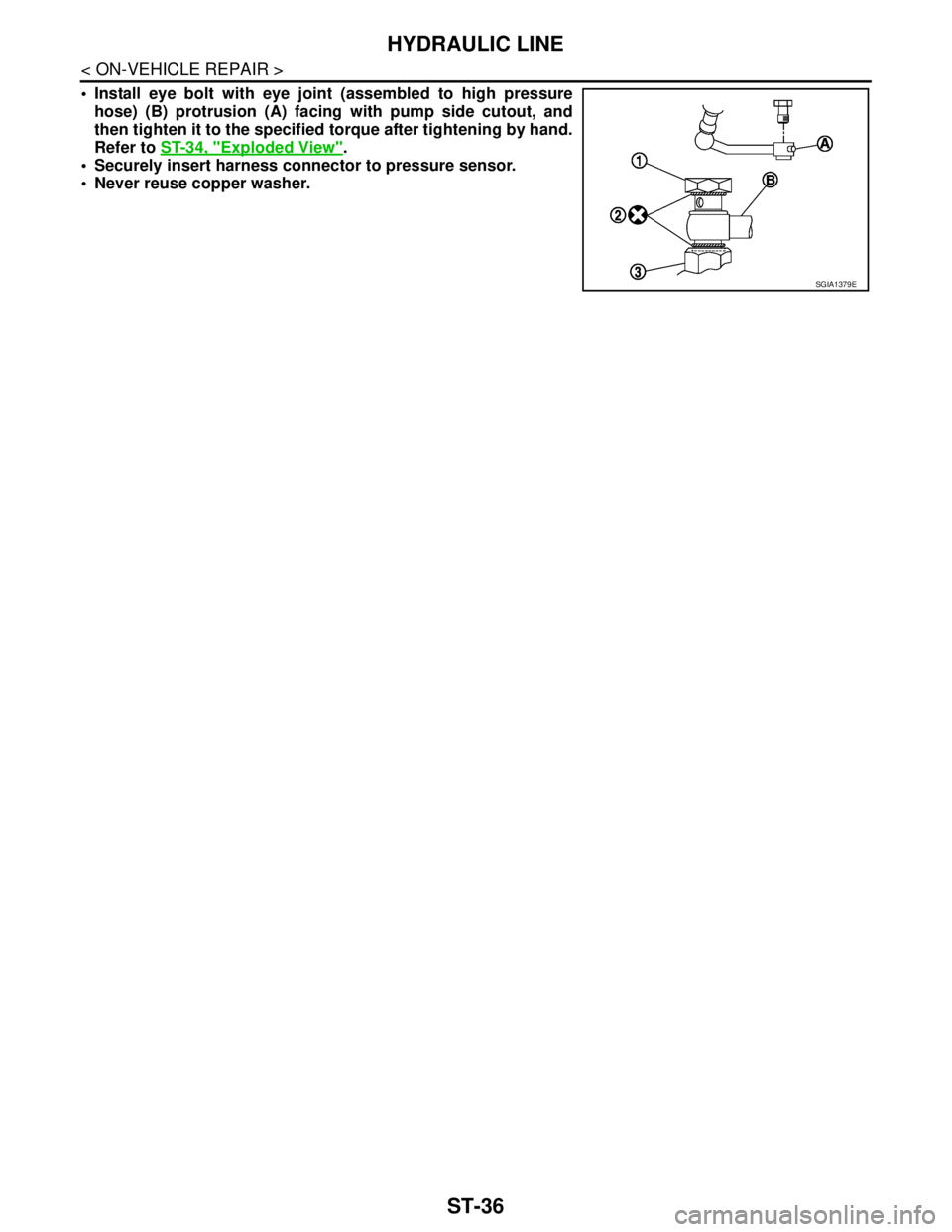
Install eye bolt with eye joint (assembled to high pressure
hose) (B) protrusion (A) facing with pump side cutout, and
then tighten it to the specified torque after tightening by hand.
Refer to ST-34, "
Exploded View".
Securely insert harness connector to pressure sensor.
Never reuse copper washer.
SGIA1379E
Page 4463 of 5121
STR-16
< ON-VEHICLE REPAIR >
STARTER MOTOR
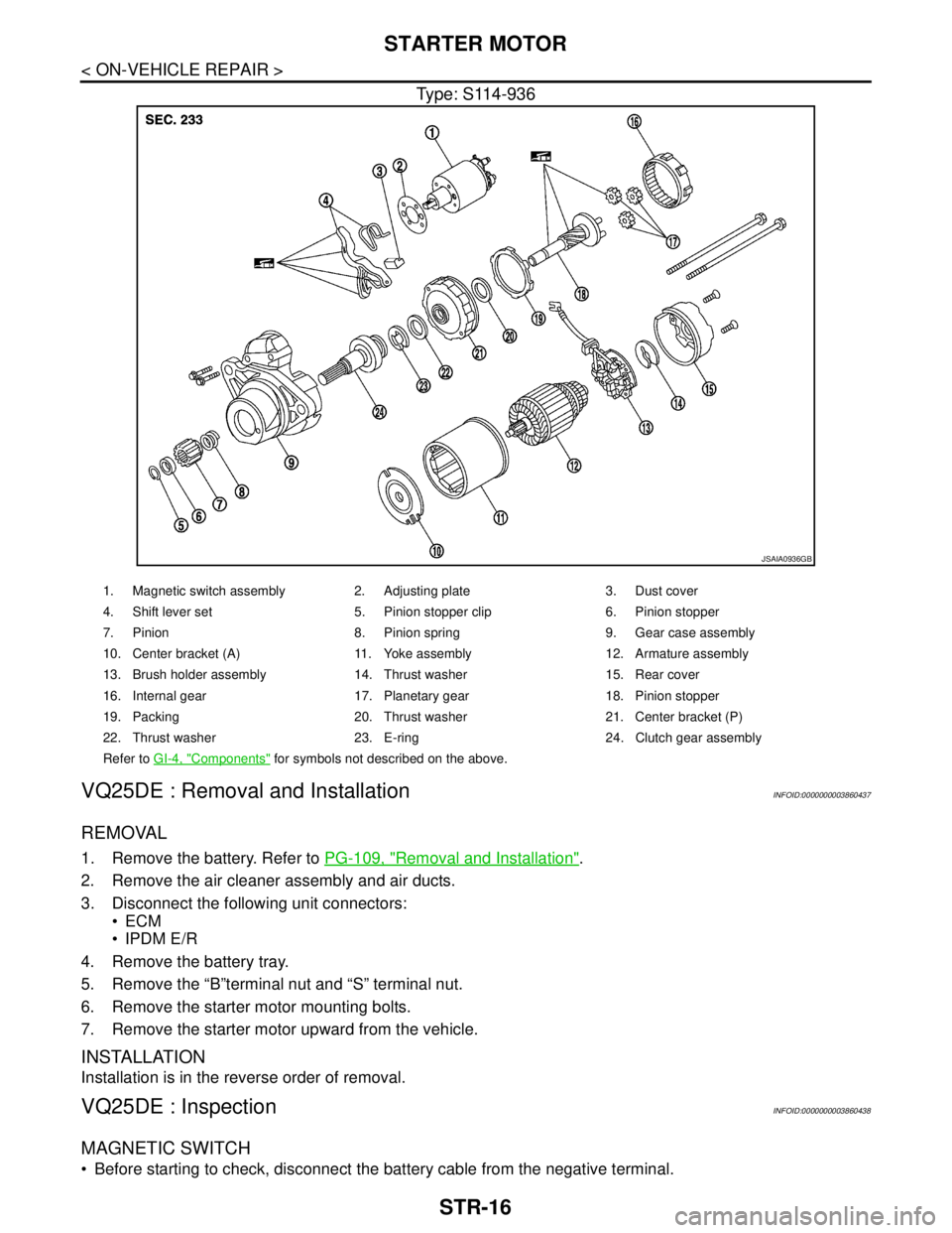
Type: S114-936
VQ25DE : Removal and InstallationINFOID:0000000003860437
REMOVAL
1. Remove the battery. Refer to PG-109, "Removal and Installation".
2. Remove the air cleaner assembly and air ducts.
3. Disconnect the following unit connectors:
ECM
IPDM E/R
4. Remove the battery tray.
5. Remove the “B”terminal nut and “S” terminal nut.
6. Remove the starter motor mounting bolts.
7. Remove the starter motor upward from the vehicle.
INSTALLATION
Installation is in the reverse order of removal.
VQ25DE : InspectionINFOID:0000000003860438
MAGNETIC SWITCH
Before starting to check, disconnect the battery cable from the negative terminal.
JSAIA0936GB
1. Magnetic switch assembly 2. Adjusting plate 3. Dust cover
4. Shift lever set 5. Pinion stopper clip 6. Pinion stopper
7. Pinion 8. Pinion spring 9. Gear case assembly
10. Center bracket (A) 11. Yoke assembly 12. Armature assembly
13. Brush holder assembly 14. Thrust washer 15. Rear cover
16. Internal gear 17. Planetary gear 18. Pinion stopper
19. Packing 20. Thrust washer 21. Center bracket (P)
22. Thrust washer 23. E-ring 24. Clutch gear assembly
Refer to GI-4, "
Components" for symbols not described on the above.