Page 5052 of 5121
WW-40
< COMPONENT DIAGNOSIS >
HEADLAMP WASHER SYSTEM
JCLWM1504GB
Page 5053 of 5121
HEADLAMP WASHER SYSTEM
WW-41
< COMPONENT DIAGNOSIS >
C
D
E
F
G
H
I
J
K
MA
B
WW
N
O
P
JCLWM1505GB
Page 5054 of 5121

WW-42
< ECU DIAGNOSIS >
BCM (BODY CONTROL MODULE)
ECU DIAGNOSIS
BCM (BODY CONTROL MODULE)
Reference ValueINFOID:0000000003941296
VALUES ON THE DIAGNOSIS TOOL
CONSULT-III MONITOR ITEM
Monitor Item Condition Value/Status
FR WIPER HIOther than front wiper switch HI Off
Front wiper switch HI On
FR WIPER LOWOther than front wiper switch LO Off
Front wiper switch LO On
FR WASHER SWFront washer switch OFF Off
Front washer switch ON On
FR WIPER INTOther than front wiper switch INT Off
Front wiper switch INT On
FR WIPER STOPFront wiper is not in STOP position Off
Front wiper is in STOP position On
INT VOLUME Wiper intermittent dial is in a dial position 1 - 7 Wiper intermittent dial position
TURN SIGNAL ROther than turn signal switch RH Off
Turn signal switch RH On
TURN SIGNAL LOther than turn signal switch LH Off
Turn signal switch LH On
TAIL LAMP SWOther than lighting switch 1ST and 2ND Off
Lighting switch 1ST or 2ND On
HI BEAM SWOther than lighting switch HI Off
Lighting switch HI On
HEAD LAMP SW 1Other than lighting switch 2ND Off
Lighting switch 2ND On
HEAD LAMP SW 2Other than lighting switch 2ND Off
Lighting switch 2ND On
PASSING SWOther than lighting switch PASS Off
Lighting switch PASS On
AUTO LIGHT SWOther than lighting switch AUTO Off
Lighting switch AUTO On
FR FOG SWFront fog lamp switch OFF Off
Front fog lamp switch ON On
RR FOG SWRear fog lamp switch OFF Off
Rear fog lamp switch ON On
DOOR SW-DRDriver door closed Off
Driver door opened On
DOOR SW-ASPassenger door closed Off
Passenger door opened On
DOOR SW-RRRear RH door closed Off
Rear RH door opened On
Page 5070 of 5121
WW-58
< ECU DIAGNOSIS >
BCM (BODY CONTROL MODULE)
107
(R/W)GroundCombination switch
INPUT 1InputCombination
switch
(Wiper intermit-
tent dial 4)All switch OFF
1.4 V
Turn signal switch LH
1.3 V
Turn signal switch RH
1.3 V
Front wiper switch LO
1.3 V
Front washer switch ON
1.3 V Te r m i n a l N o .
(Wire color)Description
ConditionVa l u e
(Approx.)
Signal nameInput/
Output +–
JPMIA0041GB
JPMIA0037GB
JPMIA0036GB
JPMIA0038GB
JPMIA0039GB
Page 5075 of 5121

BCM (BODY CONTROL MODULE)
WW-63
< ECU DIAGNOSIS >
C
D
E
F
G
H
I
J
K
MA
B
WW
N
O
P
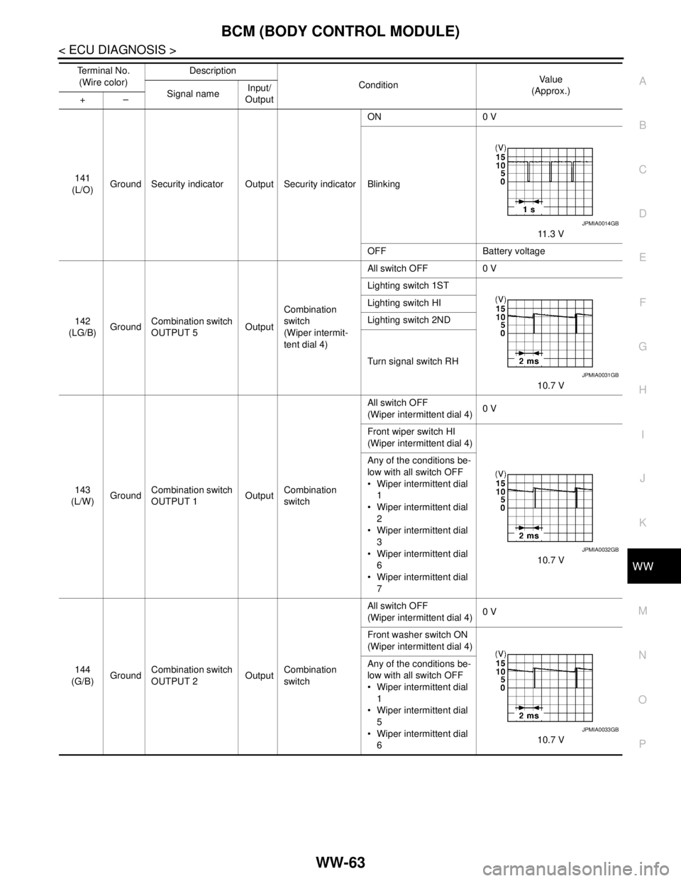
141
(L/O)Ground Security indicator Output Security indicatorON 0 V
Blinking
11.3 V
OFF Battery voltage
142
(LG/B)GroundCombination switch
OUTPUT 5OutputCombination
switch
(Wiper intermit-
tent dial 4)All switch OFF 0 V
Lighting switch 1ST
10.7 V Lighting switch HI
Lighting switch 2ND
Turn signal switch RH
143
(L/W)GroundCombination switch
OUTPUT 1OutputCombination
switchAll switch OFF
(Wiper intermittent dial 4)0 V
Front wiper switch HI
(Wiper intermittent dial 4)
10.7 V Any of the conditions be-
low with all switch OFF
Wiper intermittent dial
1
Wiper intermittent dial
2
Wiper intermittent dial
3
Wiper intermittent dial
6
Wiper intermittent dial
7
144
(G/B)GroundCombination switch
OUTPUT 2OutputCombination
switchAll switch OFF
(Wiper intermittent dial 4)0 V
Front washer switch ON
(Wiper intermittent dial 4)
10.7 V Any of the conditions be-
low with all switch OFF
Wiper intermittent dial
1
Wiper intermittent dial
5
Wiper intermittent dial
6 Te r m i n a l N o .
(Wire color)Description
ConditionVa l u e
(Approx.)
Signal nameInput/
Output +–
JPMIA0014GB
JPMIA0031GB
JPMIA0032GB
JPMIA0033GB
Page 5089 of 5121

IPDM E/R (INTELLIGENT POWER DISTRIBUTION MODULE ENGINE ROOM)
WW-77
< ECU DIAGNOSIS >
C
D
E
F
G
H
I
J
K
MA
B
WW
N
O
P
ST/INHI RLYIgnition switch ON Off
At engine cranking INHI → ST
The status of starter relay or starter control relay cannot be recognized by
the battery voltage malfunction, etc. when the starter relay is ON and the
starter control relay is OFFUNKWN
DETENT SWIgnition switch ON Press the selector button with se-
lector lever in P position
Selector lever in any position oth-
er than POff
Release the selector button with selector lever in P position On
S/L RLY -REQNone of the conditions below are present Off
Open the driver door after the ignition switch is turned OFF (for a few
seconds)
Press the push-button ignition switch when the steering lock is activat-
edOn
S/L STATESteering lock is activated LOCK
Steering lock is deactivated UNLOCK
[DTC: B210A] is detected UNKWN
DTRL REQNOTE:
The item is indicated, but not monitored.Off
OIL P SWIgnition switch OFF, ACC or engine running Open
Ignition switch ON Close
HOOD SWClose the hood Off
Open the hood On
HL WASHER REQNot operating Off
Headlamp washer operating On
THFT HRN REQNot operating Off
Horn is activated with vehicle security (theft warning) system On
HORN CHIRPNot operating Off
Door locking with Intelligent Key (horn chirp mode)
Door locking with key fob (horn chirp mode)On
CRNRNG LMP REQNOTE:
The item is indicated, but not monitored.Off Monitor Item Condition Value/Status
Page 5091 of 5121

IPDM E/R (INTELLIGENT POWER DISTRIBUTION MODULE ENGINE ROOM)
WW-79
< ECU DIAGNOSIS >
C
D
E
F
G
H
I
J
K
MA
B
WW
N
O
P
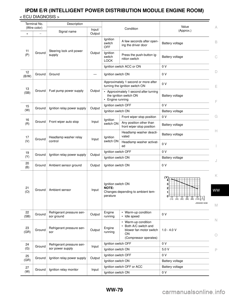
11
(P)GroundSteering lock unit power
supplyOutputIgnition
switch
OFFA few seconds after open-
ing the driver doorBattery voltage
Ignition
switch
LOCKPress the push-button ig-
nition switchBattery voltage
Ignition switch ACC or ON 0 V
12
(B/W)Ground Ground — Ignition switch ON 0 V
13
(SB)Ground Fuel pump power supply OutputApproximately 1 second or more after
turning the ignition switch ON0 V
Approximately 1 second after turning
the ignition switch ON
Engine runningBattery voltage
15
(W)Ground Ignition relay power supply OutputIgnition switch OFF 0 V
Ignition switch ON Battery voltage
16
(R)Ground Front wiper auto stop InputIgnition
switch ONFront wiper stop position 0 V
Any position other than
front wiper stop positionBattery voltage
17
(V)GroundHeadlamp washer relay
controlInputIgnition
switch ONHeadlamp washer deacti-
vatedBattery voltage
Headlamp washer activat-
ed0 V
19
(Y)Ground Ignition relay power supply OutputIgnition switch OFF 0 V
Ignition switch ON Battery voltage
20
(B)Ground Ambient sensor ground Output Ignition switch ON 0 V
21
(O)Ground Ambient sensor InputIgnition switch ON
NOTE:
Changes depending to ambient tem-
perature
22
(SB)GroundRefrigerant pressure sen-
sor groundOutputEngine
running Warm-up condition
Idle speed0 V
23
(GR)GroundRefrigerant pressure sen-
sorOutputEngine
running Warm-up condition
Both A/C switch and
blower fan motor switch
ON
(Compressor operates)1.0 - 4.0 V
24
(G)
GroundRefrigerant pressure sen-
sor power supplyInputIgnition switch OFF 0 V
Ignition switch ON 5.0 V
25
(GR)Ground Ignition relay power supply OutputIgnition switch OFF 0 V
Ignition switch ON Battery voltage
27
(W)Ground Ignition relay monitor InputIgnition switch OFF or ACC Battery voltage
Ignition switch ON 0 V Te r m i n a l N o .
(Wire color)Description
ConditionVa l u e
(Approx.)
Signal nameInput/
Output +−
JSNIA0014GB
Page 5095 of 5121

IPDM E/R (INTELLIGENT POWER DISTRIBUTION MODULE ENGINE ROOM)
WW-83
< ECU DIAGNOSIS >
C
D
E
F
G
H
I
J
K
MA
B
WW
N
O
P
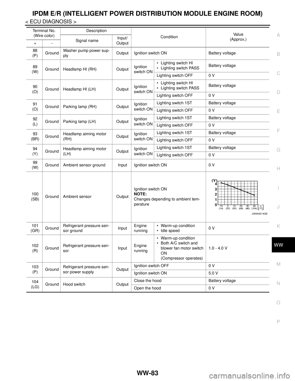
88
(P)GroundWasher pump power sup-
plyOutput Ignition switch ON Battery voltage
89
(W)Ground Headlamp HI (RH) OutputIgnition
switch ON Lighting switch HI
Lighting switch PASSBattery voltage
Lighting switch OFF 0 V
90
(O)Ground Headlamp HI (LH) OutputIgnition
switch ON Lighting switch HI
Lighting switch PASSBattery voltage
Lighting switch OFF 0 V
91
(O)Ground Parking lamp (RH) OutputIgnition
switch ONLighting switch 1ST Battery voltage
Lighting switch OFF 0 V
92
(L)Ground Parking lamp (LH) OutputIgnition
switch ONLighting switch 1ST Battery voltage
Lighting switch OFF 0 V
93
(BR)GroundHeadlamp aiming motor
(RH)OutputIgnition
switch ONLighting switch 1ST Battery voltage
Lighting switch OFF 0 V
94
(Y)GroundHeadlamp aiming motor
(LH)OutputIgnition
switch ONLighting switch 1ST Battery voltage
Lighting switch OFF 0 V
99
(W)Ground Ambient sensor ground Input Ignition switch ON 0 V
100
(SB)Ground Ambient sensor OutputIgnition switch ON
NOTE:
Changes depending to ambient tem-
perature
101
(GR)GroundRefrigerant pressure sen-
sor groundInputEngine
running Warm-up condition
Idle speed0 V
102
(R)GroundRefrigerant pressure sen-
sorInputEngine
running Warm-up condition
Both A/C switch and
blower fan motor switch
ON
(Compressor operates)1.0 - 4.0 V
103
(P)GroundRefrigerant pressure sen-
sor power supplyOutputIgnition switch OFF 0 V
Ignition switch ON 5.0 V
104
(LG)
Ground Hood switch OutputClose the hood Battery voltage
Open the hood 0 V Te r m i n a l N o .
(Wire color)Description
ConditionVa l u e
(Approx.)
Signal nameInput/
Output +−
JSNIA0014GB