Page 5100 of 5121

WW-88
< ECU DIAGNOSIS >
IPDM E/R (INTELLIGENT POWER DISTRIBUTION MODULE ENGINE ROOM)
If No CAN Communication Is Available With BCM
IGNITION RELAY MALFUNCTION DETECTION FUNCTION
IPDM E/R monitors the voltage at the contact circuit and excitation coil circuit of the ignition relay inside it.
IPDM E/R judges the ignition relay error if the voltage differs between the contact circuit and the excitation
coil circuit.
If the ignition relay cannot turn OFF due to contact seizure, it activates the tail lamp relay for 10 minutes to
alert the user to the ignition relay malfunction when the ignition switch is turned OFF.
FRONT WIPER CONTROL
IPDM E/R detects front wiper stop position by a front wiper auto stop signal.
When a front wiper auto stop signal is in the conditions listed below, IPDM E/R stops power supply to wiper
after repeating a front wiper 10 seconds activation and 20 seconds stop five times.
Control part Fail-safe operation
Cooling fan Turns ON the cooling fan relay-2 and the cooling fan relay-3 when ignition switch is
turned ON (Cooling fan operates at HI)
Turns OFF the cooling fan relay-1, the cooling fan relay-2 and the cooling fan relay-3
when the ignition switch is turned OFF (Cooling fan does not operate)
A/C compressor A/C relay OFF
Alternator Outputs the power generation command signal (PWM signal) 0%
Control part Fail-safe operation
Headlamp Turns ON the headlamp low relay when the ignition switch is turned ON
Turns OFF the headlamp low relay when the ignition switch is turned OFF
Headlamp high relay OFF
Parking lamps
License plate lamps
Illuminations
Tail lamps Turns ON the tail lamp relay when the ignition switch is turned ON
Turns OFF the tail lamp relay when the ignition switch is turned OFF
Front wiper The status just before activation of fail-safe control is maintained until the ignition
switch is turned OFF while the front wiper is operating at LO or HI speed.
The wiper is operated at LO speed until the ignition switch is turned OFF if the fail-
safe control is activated while the front wiper is set in the INT mode and the front wiper
motor is operating.
Front fog lamps Front fog lamp relay OFF
Horn Horn OFF
Ignition relay The status just before activation of fail-safe is maintained.
Starter motor Starter control relay OFF
Steering lock unit Steering lock relay OFF
Headlamp washer relay Headlamp washer relay OFF
Voltage judgment
IPDM E/R judgment Operation
Ignition relay contact sideIgnition relay excitation coil
side
ON ON Ignition relay ON normal —
OFF OFF Ignition relay OFF normal —
ON OFF Ignition relay ON stuck Detects DTC “B2098: IGN RELAY ON”
Turns ON the tail lamp relay for 10 min-
utes
OFF ON Ignition relay OFF stuck Detects DTC “B2099: IGN RELAY OFF”
Page 5102 of 5121

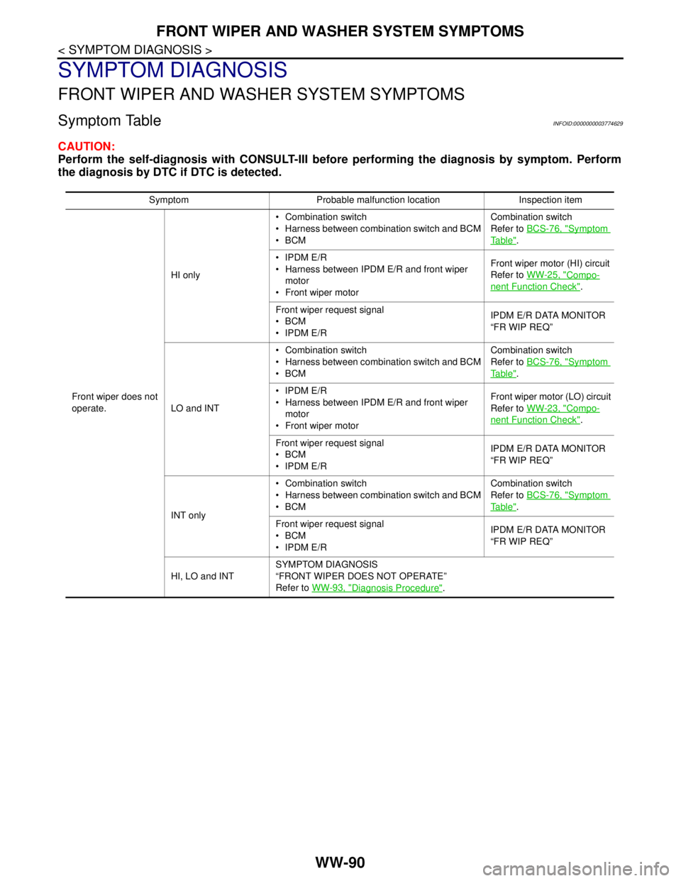
WW-90
< SYMPTOM DIAGNOSIS >
FRONT WIPER AND WASHER SYSTEM SYMPTOMS
SYMPTOM DIAGNOSIS
FRONT WIPER AND WASHER SYSTEM SYMPTOMS
Symptom TableINFOID:0000000003774629
CAUTION:
Perform the self-diagnosis with CONSULT-III before performing the diagnosis by symptom. Perform
the diagnosis by DTC if DTC is detected.
Symptom Probable malfunction location Inspection item
Front wiper does not
operate.HI only Combination switch
Harness between combination switch and BCM
BCMCombination switch
Refer to BCS-76, "
Symptom
Ta b l e".
IPDM E/R
Harness between IPDM E/R and front wiper
motor
Front wiper motorFront wiper motor (HI) circuit
Refer to WW-25, "
Compo-
nent Function Check".
Front wiper request signal
BCM
IPDM E/RIPDM E/R DATA MONITOR
“FR WIP REQ”
LO and INT Combination switch
Harness between combination switch and BCM
BCMCombination switch
Refer to BCS-76, "
Symptom
Ta b l e".
IPDM E/R
Harness between IPDM E/R and front wiper
motor
Front wiper motorFront wiper motor (LO) circuit
Refer to WW-23, "
Compo-
nent Function Check".
Front wiper request signal
BCM
IPDM E/RIPDM E/R DATA MONITOR
“FR WIP REQ”
INT only Combination switch
Harness between combination switch and BCM
BCMCombination switch
Refer to BCS-76, "
Symptom
Ta b l e".
Front wiper request signal
BCM
IPDM E/RIPDM E/R DATA MONITOR
“FR WIP REQ”
HI, LO and INTSYMPTOM DIAGNOSIS
“FRONT WIPER DOES NOT OPERATE”
Refer to WW-93, "
Diagnosis Procedure".
Page 5103 of 5121

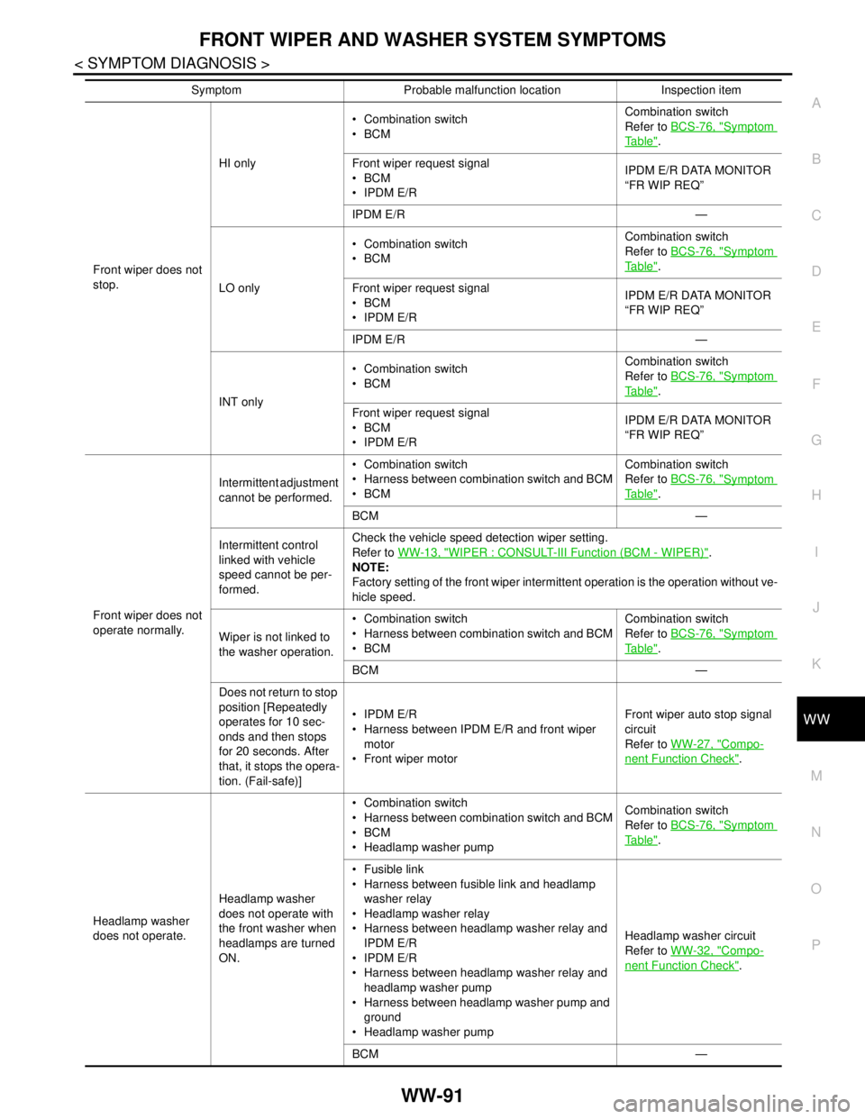
FRONT WIPER AND WASHER SYSTEM SYMPTOMS
WW-91
< SYMPTOM DIAGNOSIS >
C
D
E
F
G
H
I
J
K
MA
B
WW
N
O
P
Front wiper does not
stop.HI only Combination switch
BCMCombination switch
Refer to BCS-76, "
Symptom
Ta b l e".
Front wiper request signal
BCM
IPDM E/RIPDM E/R DATA MONITOR
“FR WIP REQ”
IPDM E/R —
LO only Combination switch
BCMCombination switch
Refer to BCS-76, "
Symptom
Ta b l e".
Front wiper request signal
BCM
IPDM E/RIPDM E/R DATA MONITOR
“FR WIP REQ”
IPDM E/R —
INT only Combination switch
BCMCombination switch
Refer to BCS-76, "
Symptom
Ta b l e".
Front wiper request signal
BCM
IPDM E/RIPDM E/R DATA MONITOR
“FR WIP REQ”
Front wiper does not
operate normally.Intermittent adjustment
cannot be performed. Combination switch
Harness between combination switch and BCM
BCMCombination switch
Refer to BCS-76, "
Symptom
Ta b l e".
BCM —
Intermittent control
linked with vehicle
speed cannot be per-
formed.Check the vehicle speed detection wiper setting.
Refer to WW-13, "
WIPER : CONSULT-III Function (BCM - WIPER)".
NOTE:
Factory setting of the front wiper intermittent operation is the operation without ve-
hicle speed.
Wiper is not linked to
the washer operation. Combination switch
Harness between combination switch and BCM
BCMCombination switch
Refer to BCS-76, "
Symptom
Ta b l e".
BCM —
Does not return to stop
position [Repeatedly
operates for 10 sec-
onds and then stops
for 20 seconds. After
that, it stops the opera-
tion. (Fail-safe)] IPDM E/R
Harness between IPDM E/R and front wiper
motor
Front wiper motorFront wiper auto stop signal
circuit
Refer to WW-27, "
Compo-
nent Function Check".
Headlamp washer
does not operate.Headlamp washer
does not operate with
the front washer when
headlamps are turned
ON. Combination switch
Harness between combination switch and BCM
BCM
Headlamp washer pumpCombination switch
Refer to BCS-76, "
Symptom
Ta b l e".
Fusible link
Harness between fusible link and headlamp
washer relay
Headlamp washer relay
Harness between headlamp washer relay and
IPDM E/R
IPDM E/R
Harness between headlamp washer relay and
headlamp washer pump
Harness between headlamp washer pump and
ground
Headlamp washer pumpHeadlamp washer circuit
Refer to WW-32, "
Compo-
nent Function Check".
BCM — Symptom Probable malfunction location Inspection item
Page 5107 of 5121
HEADLAMP WASHER DOES NOT OPERATE
WW-95
< SYMPTOM DIAGNOSIS >
C
D
E
F
G
H
I
J
K
MA
B
WW
N
O
P
HEADLAMP WASHER DOES NOT OPERATE
DescriptionINFOID:0000000003774630
Headlamp washer does not operate linked to front washer operation.
Diagnosis ProcedureINFOID:0000000003774631
1.CHECK IPDM E/R
CONSULT-III DATA MONITOR
1. Turn the lighting switch 2ND.
2. Select “HL WASHER REQ” of IPDM E/R data monitor item.
3. Operate the headlamp washer.
4. Check the status of “HL WASHER REQ”.
Is the status of item normal?
YES >> Refer to WW-32, "Component Function Check".
NO >> GO TO 2.
2.CHECK COMBINATION SWITCH
Perform the inspection of the combination switch. Refer to BCS-76, "
Symptom Table".
Is combination switch normal?
YES >> Replace BCM. Refer to BCS-78, "Exploded View".
NO >> Repair or replace the applicable parts.
Monitor item Condition Monitor status
HL WASHER REQ Headlamp washer Operating On
Stopped Off
Page 5109 of 5121
HEADLAMP WASHER NOZZLE AND TUBE
WW-97
< ON-VEHICLE REPAIR >
C
D
E
F
G
H
I
J
K
MA
B
WW
N
O
P
ON-VEHICLE REPAIR
HEADLAMP WASHER NOZZLE AND TUBE
Exploded ViewINFOID:0000000003761621
Hydraulic LayoutINFOID:0000000003761622
Removal and InstallationINFOID:0000000003761623
REMOVAL
1. Headlamp washer nozzle cover 2. Headlamp washer nozzle assembly
JPLIA1130ZZ
1. Headlamp washer nozzle assembly
(LH)2. Headlamp washer tube 3. Headlamp washer nozzle assembly
(RH)
A. Headlamp washer tube joint
: Clip
JPLIA1131ZZ
Page 5110 of 5121
WW-98
< ON-VEHICLE REPAIR >
HEADLAMP WASHER NOZZLE AND TUBE
1. Push pawl (A), and remove the headlamp washer nozzle cover
(1).
2. Remove the front bumper fascia. Refer to EXT-11, "
Exploded
View".
3. Disconnect the headlamp washer tube from the headlamp
washer nozzle assembly.
4. Remove the headlamp washer nozzle mounting bolt.
5. Remove the headlamp washer nozzle assembly from the front
bumper fascia.
INSTALLATION
Install in the reverse order of removal.
InspectionINFOID:0000000003761624
HEADLAMP WASHER NOZZLE SPRAY POSITION INSPECTION
Check that the headlamp washer injection is certainly on the head-
lamp illuminating area. If the injection is out of the area, check the
headlamp washer tube and headlamp washer nozzle leakages.
JPLIA1132ZZ
JPLIA1133ZZ
Page 5111 of 5121
WASHER TANK
WW-99
< ON-VEHICLE REPAIR >
C
D
E
F
G
H
I
J
K
MA
B
WW
N
O
P
WASHER TANK
Exploded ViewINFOID:0000000003761625
Removal and InstallationINFOID:0000000003761626
REMOVAL
1. Pull out the washer tank inlet from the washer tank.
2. Remove the front bumper fascia. Refer to EXT-11, "
Exploded View".
3. Disconnect the washer pump connector.
4. Disconnect the headlamp washer pump connector.
5. Disconnect the washer tube.
6. Disconnect the headlamp washer tube.
7. Remove the washer tank mounting bolts.
8. Remove the washer tank from the vehicle.
INSTALLATION
Install in the reverse order of removal.
CAUTION:
Add water up to the top of the washer tank inlet after installing. Check that there is no leakage.
1. Washer tank inlet 2. Washer tank
JPLIA1134ZZ
Page 5112 of 5121
WW-100
< ON-VEHICLE REPAIR >
WASHER PUMP
WASHER PUMP
Exploded ViewINFOID:0000000003761627
Removal and InstallationINFOID:0000000003761628
REMOVAL
1. Remove the fender protector RH (front). Refer to EXT-22, "FENDER PROTECTOR : Exploded View".
2. Disconnect the washer pump connector.
3. Disconnect the washer tube.
4. Remove the washer pump from the washer tank.
5. Remove the packing from the washer tank.
INSTALLATION
Install in the reverse order of removal.
CAUTION:
Never twist the packing when installing the washer pump.
1. Washer tank 2. Washer tube 3. Washer pump
4. Washer pump connector 5. Packing
: Vehicle front
JPLIA1135ZZ