2008 NISSAN LATIO cooling
[x] Cancel search: coolingPage 2388 of 2771
MTC-50
< SERVICE INFORMATION >
TROUBLE DIAGNOSIS
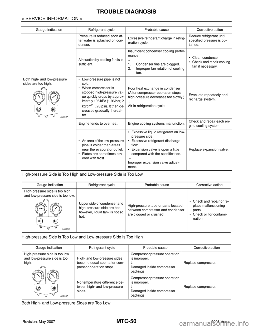
High-pressure Side is Too High and Low-pressure Side is Too Low
High-pressure Side is Too Low and Low-pressure Side is Too High
Both High- and Low-pressure Sides are Too Low
Gauge indication Refrigerant cycle Probable cause Corrective action
Both high- and low-pressure
sides are too high.Pressure is reduced soon af-
ter water is splashed on con-
denser.Excessive refrigerant charge in refrig-
eration cycle.Reduce refrigerant until
specified pressure is ob-
tained.
Air suction by cooling fan is in-
sufficient.Insufficient condenser cooling perfor-
mance.
↓
1. Condenser fins are clogged.
2. Improper fan rotation of cooling
fan.• Clean condenser.
• Check and repair cooling
fan if necessary.
• Low-pressure pipe is not
cold.
• When compressor is
stopped high-pressure val-
ue quickly drops by approx-
imately 196 kPa (1.96 bar, 2
kg/cm
2 , 28 psi). It then de-
creases gradually thereaf-
ter.Poor heat exchange in condenser
(After compressor operation stops,
high-pressure decreases too slowly.).
↓
Air in refrigeration cycle.Evacuate repeatedly and
recharge system.
Engine tends to overheat. Engine cooling systems malfunction.Check and repair each en-
gine cooling system.
• An area of the low-pressure
pipe is colder than areas
near the evaporator outlet.
• Plates are sometimes cov-
ered with frost.• Excessive liquid refrigerant on low-
pressure side.
• Excessive refrigerant discharge
flow.
• Expansion valve is open a little
compared with the specification.
↓
Improper expansion valve adjust-
ment.Replace expansion valve.
AC359A
Gauge indication Refrigerant cycle Probable cause Corrective action
High-pressure side is too high
and low-pressure side is too low.
Upper side of condenser and
high-pressure side are hot,
however, liquid tank is not so
hot.High-pressure tube or parts located
between compressor and condenser
are clogged or crushed.• Check and repair or re-
place malfunctioning
parts.
• Check oil for contami-
nation.
AC360A
Gauge indication Refrigerant cycle Probable cause Corrective action
High-pressure side is too low
and low-pressure side is too
high.High- and low-pressure sides
become equal soon after com-
pressor operation stops.Compressor pressure operation
is improper.
↓
Damaged inside compressor
packings.Replace compressor.
No temperature difference be-
tween high- and low-pressure
sides.Compressor pressure operation
is improper.
↓
Damaged inside compressor
packings.Replace compressor.
AC356A
Page 2390 of 2771
MTC-52
< SERVICE INFORMATION >
TROUBLE DIAGNOSIS
Insufficient Heating
INFOID:0000000001704307
SYMPTOM: Insufficient heating
INSPECTION FLOW
1.CONFIRM SYMPTOM BY PERFORMING OPERATIONAL CHECK - TEMPERATURE DECREASE
1. Turn temperature control dial clockwise to maximum heat position.
2. Check for hot air at discharge air outlets.
Can the symptom be duplicated?
YES >> GO TO 3.
NO >> GO TO 2.
2.CHECK FOR ANY SYMPTOMS
Perform a complete operational check for any symptoms. Refer to MTC-30, "
Operational Check" .
Does another symptom exist?
YES >> Refer to MTC-22, "How to Perform Trouble Diagnosis for Quick and Accurate Repair" .
NO >> System OK.
3.CHECK FOR SERVICE BULLETINS
Check for any service bulletins.
>> GO TO 4.
4.CHECK COOLANT SYSTEM
1. Check engine coolant level. Refer to CO-8
.
2. Check hoses for leaks or kinks.
3. Check Radiator cap. Refer to CO-13, "
Checking Radiator Cap" .
OK or NG
OK >> GO TO 5.
NG >> Repair/replace as necessary.
5.CHECK AIR MIX DOOR CABLE
Check air mix door cable operation. Refer to MTC-64, "
Air Mix Door Cable Adjustment" .
OK or NG
YES >> GO TO 6.
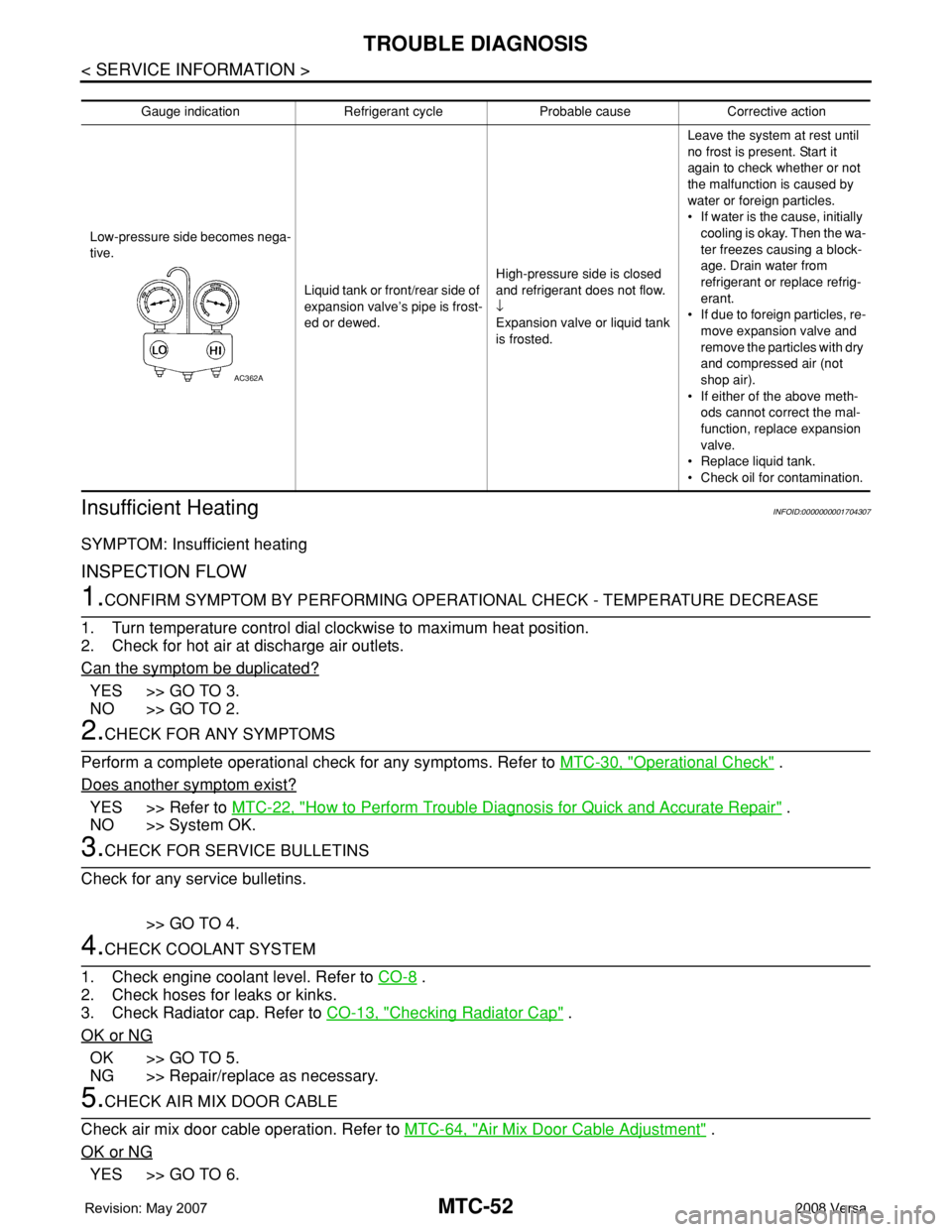
Gauge indication Refrigerant cycle Probable cause Corrective action
Low-pressure side becomes nega-
tive.
Liquid tank or front/rear side of
expansion valve’s pipe is frost-
ed or dewed.High-pressure side is closed
and refrigerant does not flow.
↓
Expansion valve or liquid tank
is frosted.Leave the system at rest until
no frost is present. Start it
again to check whether or not
the malfunction is caused by
water or foreign particles.
• If water is the cause, initially
cooling is okay. Then the wa-
ter freezes causing a block-
age. Drain water from
refrigerant or replace refrig-
erant.
• If due to foreign particles, re-
move expansion valve and
remove the particles with dry
and compressed air (not
shop air).
• If either of the above meth-
ods cannot correct the mal-
function, replace expansion
valve.
• Replace liquid tank.
• Check oil for contamination.
AC362A
Page 2396 of 2771
MTC-58
< SERVICE INFORMATION >
A/C UNIT ASSEMBLY
A/C UNIT ASSEMBLY
Removal and InstallationINFOID:0000000001704312
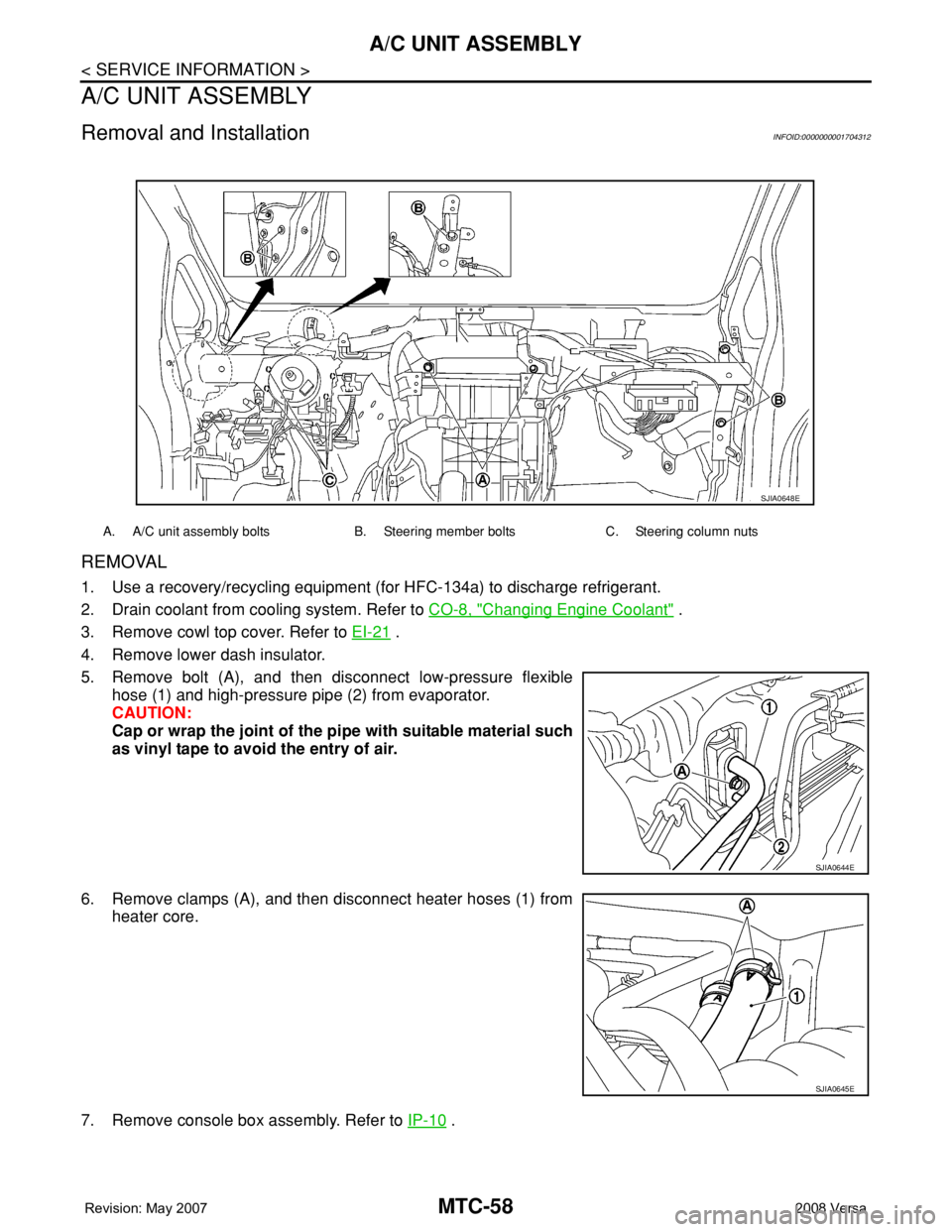
REMOVAL
1. Use a recovery/recycling equipment (for HFC-134a) to discharge refrigerant.
2. Drain coolant from cooling system. Refer to CO-8, "
Changing Engine Coolant" .
3. Remove cowl top cover. Refer to EI-21
.
4. Remove lower dash insulator.
5. Remove bolt (A), and then disconnect low-pressure flexible
hose (1) and high-pressure pipe (2) from evaporator.
CAUTION:
Cap or wrap the joint of the pipe with suitable material such
as vinyl tape to avoid the entry of air.
6. Remove clamps (A), and then disconnect heater hoses (1) from
heater core.
7. Remove console box assembly. Refer to IP-10
.
A. A/C unit assembly bolts B. Steering member bolts C. Steering column nuts
SJIA0648E
SJIA0644E
SJIA0645E
Page 2413 of 2771
REFRIGERANT LINES
MTC-75
< SERVICE INFORMATION >
C
D
E
F
G
H
I
K
L
MA
B
MTC
N
O
P
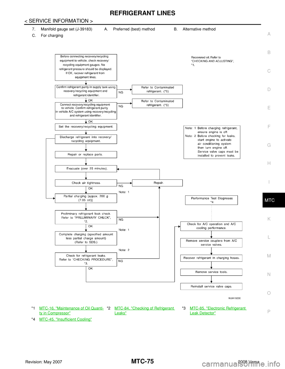
7. Manifold gauge set (J-39183) A. Preferred (best) method B. Alternative method
C. For charging
*1MTC-16, "
Maintenance of Oil Quanti-
ty in Compressor"
*2MTC-84, "Checking of Refrigerant
Leaks"
*3MTC-85, "Electronic Refrigerant
Leak Detector"
*4MTC-45, "Insufficient Cooling"
WJIA1923E
Page 2425 of 2771
REFRIGERANT LINES
MTC-87
< SERVICE INFORMATION >
C
D
E
F
G
H
I
K
L
MA
B
MTC
N
O
P
Check all around the service valves. Ensure service valve caps are secured on the service valves (to
prevent leaks).
NOTE:
After removing A/C manifold gauge set from service valves, wipe any residue from valves to prevent any
false readings by leak detector.
• Cooling unit (Evaporator)
With engine OFF, turn blower fan on “High” for at least 15 seconds to dissipate any refrigerant trace in
the cooling unit. Wait a minimum of 10 minutes accumulation time (refer to the manufacturer’s recom-
mended procedure for actual wait time) before inserting the leak detector probe into the drain hose.
Keep the probe inserted for at least 10 seconds. Use caution not to contaminate the probe tip with water
or dirt that may be in the drain hose.
5. If a leak detector detects a leak, verify at least once by blowing compressed air into area of suspected
leak, then repeat check as outlined above.
6. Do not stop when one leak is found. Continue to check for additional leaks at all system components.
If no leaks are found, perform steps 7-10.
7. Start engine.
8. Set the heater A/C control as follows;
a. A/C switch: ON
b. Mode control dial position: VENT (Ventilation)
c. Intake door lever position: Recirculation
d. Max. cold temperature
e. Fan speed: High
9. Run engine at 1,500 rpm for at least 2 minutes.
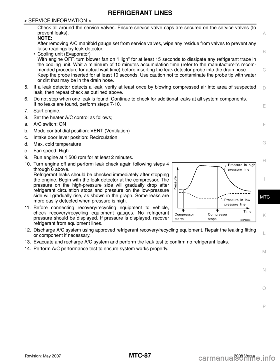
10. Turn engine off and perform leak check again following steps 4
through 6 above.
Refrigerant leaks should be checked immediately after stopping
the engine. Begin with the leak detector at the compressor. The
pressure on the high-pressure side will gradually drop after
refrigerant circulation stops and pressure on the low-pressure
side will gradually rise, as shown in the graph. Some leaks are
more easily detected when pressure is high.
11. Before connecting recovery/recycling equipment to vehicle,
check recovery/recycling equipment gauges. No refrigerant
pressure should be displayed. If pressure is displayed, recover
refrigerant from equipment lines.
12. Discharge A/C system using approved refrigerant recovery/recycling equipment. Repair the leaking fitting
or component if necessary.
13. Evacuate and recharge A/C system and perform the leak test to confirm no refrigerant leaks.
14. Perform A/C performance test to ensure system works properly.
SHA839E
Page 2449 of 2771

PG-16
< SERVICE INFORMATION >
IPDM E/R (INTELLIGENT POWER DISTRIBUTION MODULE ENGINE ROOM)
IPDM E/R (INTELLIGENT POWER DISTRIBUTION MODULE ENGINE
ROOM)
System DescriptionINFOID:0000000001704697
• IPDM E/R (Intelligent Power Distribution Module Engine Room) integrates the relay box and fuse block
which were originally placed in engine compartment. It controls integrated relays via IPDM E/R control cir-
cuits.
• IPDM E/R-integrated control circuits perform ON-OFF operation of relays, CAN communication control, oil
pressure switch signal reception, etc.
• It controls operation of each electrical component via ECM, BCM and CAN communication lines.
CAUTION:
None of the IPDM E/R integrated relays can be removed.
SYSTEMS CONTROLLED BY IPDM E/R
1. Lamp control
Using CAN communication lines, it receives signals from the BCM and controls the following lamps:
• Headlamps (High, Low)
• Parking lamps
• Tail and license plate lamps
• Front fog lamps
2. Wiper control
Using CAN communication lines, it receives signals from the BCM and controls the front wipers.
3. Rear window defogger relay control
Using CAN communication lines, it receives signals from the BCM and controls the rear window defogger
relay.
4. A/C compressor control
Using CAN communication lines, it receives signals from the ECM and controls the A/C compressor
(magnet clutch).
5. Starter control
Using CAN communication lines, it receives signals from the BCM and controls the starter relay.
6. Cooling fan control
Using CAN communication lines, it receives signals from the ECM and controls the cooling fan relays.
7. Horn control
Using CAN communication lines, it receives signals from the BCM and controls the horn relay.
8. Daytime light system control (Canada only)
Using CAN communication lines, it receives signals from the BCM and controls the daytime light relay.
CAN COMMUNICATION LINE CONTROL
With CAN communication, by connecting each control unit using two communication lines (CAN L-line, CAN
H-line), it is possible to transmit a maximum amount of information with minimum wiring. Each control unit can
transmit and receive data, and reads necessary information only.
1. Fail-safe control
• When CAN communication with other control units is impossible, IPDM E/R performs fail-safe control.
After CAN communication returns to normal operation, it also returns to normal control.
• Operation of control parts by IPDM E/R during fail-safe mode is as follows:
Controlled system Fail-safe mode
Headlamp• With the ignition switch ON, headlamp low relay is ON, headlamp high relays are OFF, and
daytime light system (Canada only) is OFF.
• With the ignition switch OFF, the headlamp relays are OFF.
Tail, license plate and parking lamps • With the ignition switch ON, the tail lamp relay is ON.
• With the ignition switch OFF, the tail lamp relay is OFF.
Cooling fan• With the ignition switch ON, cooling fan relay-1, relay-2, and relay-3 are ON.
• With the ignition switch OFF, all cooling fan relays are OFF.
Front wiperUntil the ignition switch is turned off, the front wiper relays remain in the same status they
were in just before fail−safe control was initiated.
Page 2452 of 2771
IPDM E/R (INTELLIGENT POWER DISTRIBUTION MODULE ENGINE ROOM)
PG-19
< SERVICE INFORMATION >
C
D
E
F
G
H
I
J
L
MA
B
PG
N
O
P
*1 Perform monitoring of IPDM E/R data with the ignition switch ON. When the ignition switch is in ACC position, display may not be cor-
rect.
*2 This item is displayed, but does not function.
CAN DIAG SUPPORT MNTR
Refer to LAN-8 .
ACTIVE TEST
Display Item List
Auto Active TestINFOID:0000000001704701
DESCRIPTION
• In auto active test mode, operation inspection can be performed when IPDM E/R sends a drive signal to the
following systems:
- Rear window defogger
- Front wipers
- Tail, license and parking lamps
- Daytime lamp system (Canada only)
- Front fog lamps
- Headlamps (High, Low)
- A/C compressor (magnet clutch)
- Cooling fan
OPERATION PROCEDURE
1. Close hood and front door RH, and lift wiper arms away from windshield (to prevent glass damage by
wiper operation).
NOTE:
When auto active test is performed with hood opened, sprinkle water on windshield beforehand.
2. Turn ignition switch OFF.
3. Turn ignition switch ON and, within 20 seconds, press front door switch LH 20 times. Then turn ignition
switch OFF.
4. Turn ignition switch ON within 10 seconds after ignition switch OFF.
5. When auto active test mode is actuated, horn chirps once.
6. After a series of operations is repeated three times, auto active test is completed.
Theft warning
horn requestTHFT HRN REQ ON/OFF X X Signal status input from BCM
Horn chirp HORN CHIRP ON/OFF X X Output status of IPDM E/R
Daytime light re-
questDTRL REQ ON/OFF X X Signal status input from BCM Item nameCONSULT-III
screen display Display or unitMonitor item selection
Description
ALL
SIGNALSMAIN
SIGNALSSELECTION
FROM MENU
Test name CONSULT-III screen display Description
Head, tail, fog lamp output EXTERNAL LAMPSWith a certain ON-OFF operation (OFF, TAIL, LO, HI, FOG), the front
fog lamp, headlamp low, headlamp high RH, headlamp high LH, and
tail lamp relays can be operated.
Rear defogger output REAR DEFOGGERWith a certain ON-OFF operation, the rear defogger relay can be oper-
ated.
Front wiper (HI, LO) output FRONT WIPERWith a certain operation (OFF, HI ON, LO ON), the front wiper relays
(Lo, Hi) can be operated.
Cooling fan output MOTOR FANWith a certain operation (1, 2, 3, 4), the cooling fan relays can be oper-
ated.
Horn output HORN With a certain ON-OFF operation, the horn relay can be operated.
Page 2453 of 2771
PG-20
< SERVICE INFORMATION >
IPDM E/R (INTELLIGENT POWER DISTRIBUTION MODULE ENGINE ROOM)
NOTE:
When auto active test mode has to be cancelled halfway, turn ignition switch OFF.
CAUTION:
Be sure to perform BL-37, "
Door Switch Check (Hatchback)" when the auto active test cannot be
performed.
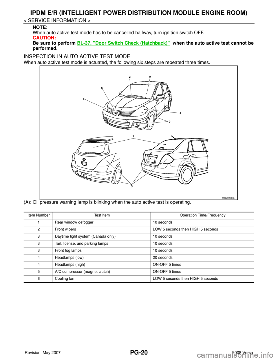
INSPECTION IN AUTO ACTIVE TEST MODE
When auto active test mode is actuated, the following six steps are repeated three times.
(A): Oil pressure warning lamp is blinking when the auto active test is operating.
WKIA5988E
Item Number Test Item Operation Time/Frequency
1 Rear window defogger 10 seconds
2 Front wipers LOW 5 seconds then HIGH 5 seconds
3 Daytime light system (Canada only) 10 seconds
3 Tail, license, and parking lamps 10 seconds
3 Front fog lamps 10 seconds
4 Headlamps (low) 20 seconds
4 Headlamps (high) ON-OFF 5 times
5 A/C compressor (magnet clutch) ON-OFF 5 times
6 Cooling fan LOW 5 seconds then HIGH 5 seconds