2008 NISSAN LATIO length
[x] Cancel search: lengthPage 2522 of 2771

PS-16
< SERVICE INFORMATION >
POWER STEERING GEAR
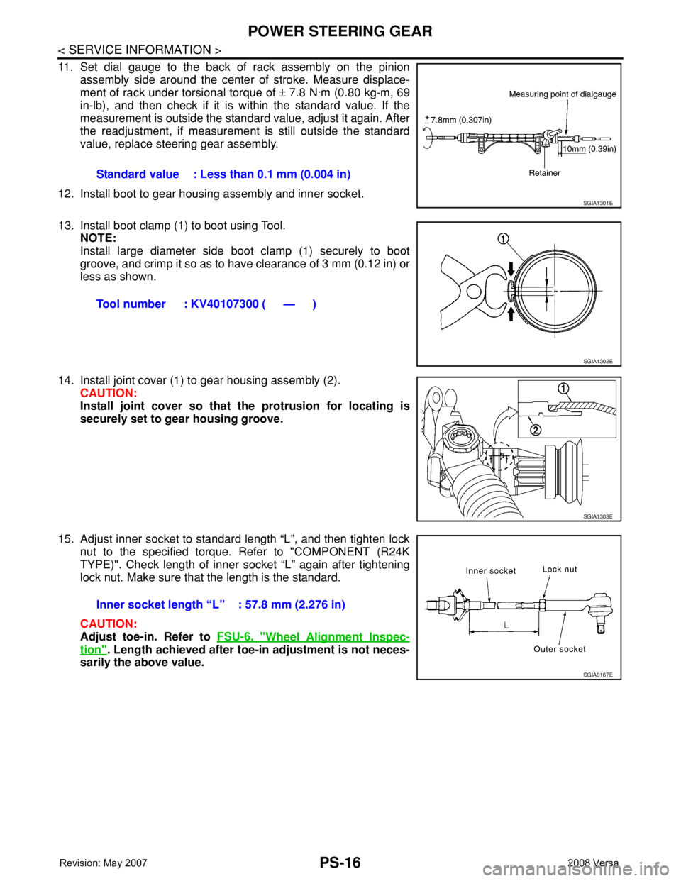
11. Set dial gauge to the back of rack assembly on the pinion
assembly side around the center of stroke. Measure displace-
ment of rack under torsional torque of ± 7.8 N·m (0.80 kg-m, 69
in-lb), and then check if it is within the standard value. If the
measurement is outside the standard value, adjust it again. After
the readjustment, if measurement is still outside the standard
value, replace steering gear assembly.
12. Install boot to gear housing assembly and inner socket.
13. Install boot clamp (1) to boot using Tool.
NOTE:
Install large diameter side boot clamp (1) securely to boot
groove, and crimp it so as to have clearance of 3 mm (0.12 in) or
less as shown.
14. Install joint cover (1) to gear housing assembly (2).
CAUTION:
Install joint cover so that the protrusion for locating is
securely set to gear housing groove.
15. Adjust inner socket to standard length “L”, and then tighten lock
nut to the specified torque. Refer to "COMPONENT (R24K
TYPE)". Check length of inner socket “L” again after tightening
lock nut. Make sure that the length is the standard.
CAUTION:
Adjust toe-in. Refer to FSU-6, "
Wheel Alignment Inspec-
tion". Length achieved after toe-in adjustment is not neces-
sarily the above value.Standard value : Less than 0.1 mm (0.004 in)
SGIA1301E
Tool number : KV40107300 ( — )
SGIA1302E
SGIA1303E
Inner socket length “L” : 57.8 mm (2.276 in)
SGIA0167E
Page 2523 of 2771

SERVICE DATA AND SPECIFICATIONS (SDS)
PS-17
< SERVICE INFORMATION >
C
D
E
F
H
I
J
K
L
MA
B
PS
N
O
P
SERVICE DATA AND SPECIFICATIONS (SDS)
Steering WheelINFOID:0000000001703864
Steering AngleINFOID:0000000001703865
Steering ColumnINFOID:0000000001703866
Steering Outer Socket and Inner SocketINFOID:0000000001703867
Steering wheel axial end play 0 mm (0 in)
Steering wheel play 0 - 35 mm (0 - 1.38 in)
Steering wheel turning force Less than 36 N (3.7 kg-f, 8.2 lb-f)
Inner wheel
Degree minute (Decimal degree)Minimum 35° 00′ (35.0°)
Nominal 38° 00′ (38.0°)
Maximum 39° 00′ (39.0°)
Outer wheel
Degree minute (Decimal degree)33° 00′ (33.0°)
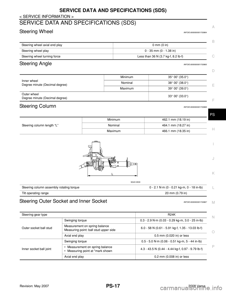
Steering column length “L”Minimum 462.1 mm (18.19 in)
Nominal 464.1 mm (18.27 in)
Maximum 466.1 mm (18.35 in)
Steering column assembly rotating torque 0 - 2.1 N·m (0 - 0.21 kg-m, 0 - 18 in-lb)
Tilt operating range20 mm (0.79 in)
SGIA1293E
Steering gear typeR24K
Outer socket ball studSwinging torque 0.3 - 2.9 N·m (0.03 - 0.29 kg-m, 3.0 - 25 in-lb)
Measurement on spring balance
Measuring point: ball stud upper side6.0 - 58 N (0.61 - 5.91 kg-f, 1.35 - 13.03 lb-f)
Axial end play 0.5 mm (0.020 in) or less
Inner socket ball jointSwinging torque 0.5 - 5.0 N·m (0.06 - 0.51 kg-m, 5 - 44 in-lb)
• Measurement on spring balance
• Measuring point at *mark shown4.3 - 43.5 N (0.44 - 4.44 kg-f, 0.97 - 9.79 lb-f)
Axial end play 0.2 mm (0.008 in) or less
Page 2524 of 2771

PS-18
< SERVICE INFORMATION >
SERVICE DATA AND SPECIFICATIONS (SDS)
Steering Gear
INFOID:0000000001703868
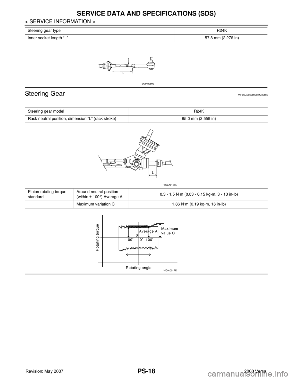
Inner socket length “L”57.8 mm (2.276 in) Steering gear typeR24K
SGIA0950E
Steering gear modelR24K
Rack neutral position, dimension “L” (rack stroke) 65.0 mm (2.559 in)
Pinion rotating torque
standardAround neutral position
(within ± 100°) Average A0.3 - 1.5 N·m (0.03 - 0.15 kg-m, 3 - 13 in-lb)
Maximum variation C 1.86 N·m (0.19 kg-m, 16 in-lb)
WGIA0185E
MGIA0017E
Page 2579 of 2771

SB-8
< ON-VEHICLE REPAIR >
SEAT BELTS
• The seat belt was damaged in an accident. (i.e. torn webbing, bent retractor or guide, etc.)
• The seat belt attaching point was damaged in an accident. Inspect the seat belt attaching area for damage
or distortion and repair as necessary before installing a new seat belt assembly.
• Anchor bolts are deformed or worn out.
• The seat belt pre-tensioner should be replaced even if the seat belts are not in use during a frontal collision
in which the air bags are deployed.
PRELIMINARY CHECKS
1. Check the seat belt warning lamp/chime for proper operation as follows:
a. Switch ignition ON. The seat belt warning lamp should illuminate. Also, the seat belt warning chime should
sound for about seven seconds.
b. Fasten driver's seat belt. The seat belt warning lamp should go out and the chime (if sounding) should
stop.
2. If the air bag warning lamp is blinking, conduct self-diagnosis using CONSULT-II, and air bag warning
lamp. Refer to SRS-18, "
SRS Operation Check".
3. Check that the seat belt retractor, seat belt anchor and buckle bolts are securely attached.
4. Check the shoulder seat belt guide and shoulder belt height adjuster for front seats. Make sure guide
swivels freely and that webbing lays flat and does not bind in guide. Make sure height adjuster operates
properly and holds securely.
5. Check retractor operation:
a. Fully extend the seat belt webbing and check for twists, tears or other damage.
b. Allow the seat belt to retract. Make sure that webbing returns smoothly and completely into the retractor. If
the seat belt does not return smoothly, wipe the inside of the loops with a clean paper cloth. Dirt build-up
in the loops of the upper anchors can cause the seat belts to retract slowly.
c. Fasten the seat belt. Check the seat belt returns smoothly and completely to the retractor. If the webbing
does not return smoothly, the cause may be an accumulation of dust or dirt. Use the “SEAT BELT TAPE
SET” and perform the following steps.
Inspect the front seat belt though-anchor 1. Pull the seat belt out to a length of 500 mm (19.69 in) or more.
2. Use a clip or other device to attach the seat belt at the center pillar webbing opening.
3. Pass a thin wire though the D-ring anchor webbing opening. Hold both ends of the wire and pull taut
while moving it up and down several times along the webbing opening surface to remove matter stuck
there.
4. Any dirt that cannot be removed with the wire can be removed by cleaning the opening with a clean
cloth.
5. Apply tape at the point where the webbing contacts the though-anchor webbing opening.
NOTE:
Apply the tape so that there is no looseness or wrinkling.
6. Remove the clip attaching the seat belt and check that the webbing returns smoothly.
6. Repeat steps above as necessary to check the other seat belts.
SEAT BELT RETRACTOR ON-VEHICLE CHECK
Emergency Locking Retractors (ELR) and Automatic Locking Retractors (ALR)
NOTE:
All seat belt retractors are of the Emergency Locking Retractors (ELR) type. In an emergency (sudden stop)
the retractor will lock and prevent the webbing from extending any further. All 3-point type seat belt retractors
except the driver's seat belt also have an Automatic Locking Retractors (ALR) mode. The ALR mode (also
called child restraint mode) is used when installing child seats. The ALR mode is activated when the seat belt
is fully extended. When the webbing is then retracted partially, the ALR mode automatically locks the seat belt
in a specific position so the webbing cannot be extended any further. To cancel the ALR mode, allow the seat
belt to fully wind back into the retractor.
Check the seat belt retractors using the following test(s) to determine if a retractor assembly is operating prop-
erly.
ELR Function Stationary Check
Grasp the shoulder webbing and pull it forward quickly. The retractor should lock and prevent the belt from
extending further.
Page 2580 of 2771

SEAT BELTS
SB-9
< ON-VEHICLE REPAIR >
C
D
E
F
G
I
J
K
L
MA
B
SB
N
O
P ALR Function Stationary Check
1. Pull out entire length of seat belt from retractor until a click is heard.
2. Retract the webbing partially. A clicking noise should be heard as the webbing retracts, indicating that the
retractor is in the Automatic Locking Retractors (ALR) mode.
3. Grasp the seat belt and try to pull out the retractor. The webbing must lock and not extend any further. If
NG, replace the retractor assembly.
4. Allow the entire length of the webbing to retract to cancel the automatic locking mode.
ELR Function Moving Check
WARNING:
Perform the following test in a safe, open area clear of other vehicles and obstructions (for example, a
large, empty parking lot). Road surface must be paved and dry. DO NOT perform the following test on
wet or gravel roads or on public streets and highways. This could result in an accident and serious
personal injury. The driver and passenger must be prepared to brace themselves in the event the
retractor does not lock.
1. Fasten driver's seat belt. Buckle a passenger into the seat for the belt that is to be tested.
2. Proceed to the designated safe area.
3. Drive the vehicle at approximately 16 km/h (10 MPH). Notify any passengers of a pending sudden stop
and the driver and passenger must be prepared to brace themselves in the event the retractor does not
lock, apply brakes firmly and make a very hard stop.
During the stop, seat belts should lock and not be extended. If the seat belt retractor assembly does not lock,
perform the retractor off-vehicle check.
SEAT BELT RETRACTOR OFF-VEHICLE CHECK
1. Remove the seat belt retractor. Refer to SB-3.
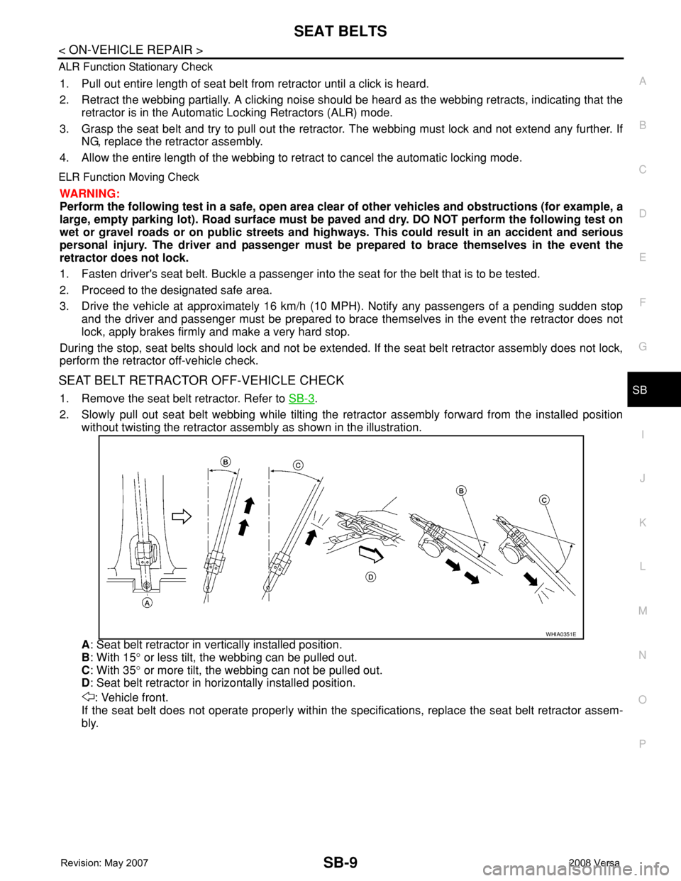
2. Slowly pull out seat belt webbing while tilting the retractor assembly forward from the installed position
without twisting the retractor assembly as shown in the illustration.
A: Seat belt retractor in vertically installed position.
B: With 15° or less tilt, the webbing can be pulled out.
C: With 35° or more tilt, the webbing can not be pulled out.
D: Seat belt retractor in horizontally installed position.
: Vehicle front.
If the seat belt does not operate properly within the specifications, replace the seat belt retractor assem-
bly.
WHIA0351E
Page 2608 of 2771

SC-26
< SERVICE INFORMATION >
SERVICE DATA AND SPECIFICATIONS (SDS)
SERVICE DATA AND SPECIFICATIONS (SDS)
BatteryINFOID:0000000001704356
StarterINFOID:0000000001704357
GeneratorINFOID:0000000001704358
M/T, A/T CVT
Type TR4 Gr.51 R
20 hours rate capacity 12 V - 47 AH 12 V - 47 AH
Cold Cranking Amps. (CCA) 470 470
Typ eS114 - 901
HITACHI make
Reduction gear type
System voltage12 V
No-loadTerminal voltage 11 V
Current Less than 110 A
Revolution More than 3,000 rpm
Minimum diameter of commutator 28.0 mm (1.102 in)
Minimum length of brush 10.5 mm (0.413 in)
Brush spring tension 16.2 N (1.65 kg, 3.64 lb)
Clearance between bearing metal and armature shaft Less than 0.2 mm (0.008 in)
Movement “L” in height of pinion assembly 0.3 - 2.5 mm (0.012 - 0.098 in)
Ty p eLR1140 - 803
MITSUBISHI make
Nominal rating12 V - 140 A
Ground polarityNegative
Minimum revolution under no-load (when 13.5 V is applied) Less than 1,200 rpm
Hot output current (when 13.5 V is applied)More than 27 A/1,300 rpm
More than 95 A/2,500 rpm
More than 116 A/5,000 rpm
Regulated output voltage14.1 - 14.7 V
Minimum length of brush More than 6.00 mm (0.236 in)
Brush spring pressure 1.1 - 3.7 N (112 - 378 g, 4.00 - 13.3 oz)
Slip ring minimum outer diameter More than 14.7 mm (0.579 in)
Rotor (field coil) resistance 1.61 - 1.91 Ω