Page 1818 of 2771

FAX-22
< SERVICE INFORMATION >
FRONT DRIVE SHAFT
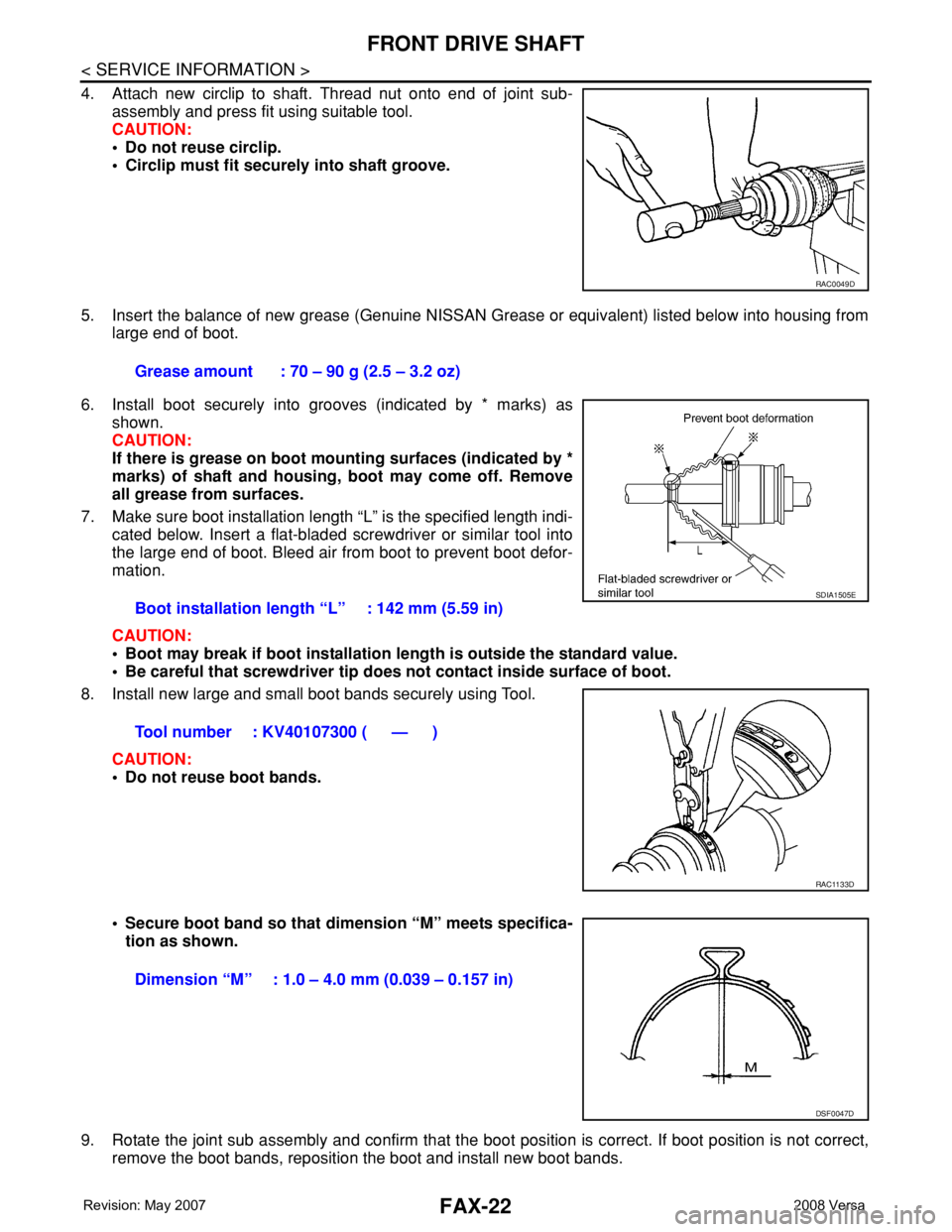
4. Attach new circlip to shaft. Thread nut onto end of joint sub-
assembly and press fit using suitable tool.
CAUTION:
• Do not reuse circlip.
• Circlip must fit securely into shaft groove.
5. Insert the balance of new grease (Genuine NISSAN Grease or equivalent) listed below into housing from
large end of boot.
6. Install boot securely into grooves (indicated by * marks) as
shown.
CAUTION:
If there is grease on boot mounting surfaces (indicated by *
marks) of shaft and housing, boot may come off. Remove
all grease from surfaces.
7. Make sure boot installation length “L” is the specified length indi-
cated below. Insert a flat-bladed screwdriver or similar tool into
the large end of boot. Bleed air from boot to prevent boot defor-
mation.
CAUTION:
• Boot may break if boot installation length is outside the standard value.
• Be careful that screwdriver tip does not contact inside surface of boot.
8. Install new large and small boot bands securely using Tool.
CAUTION:
• Do not reuse boot bands.
• Secure boot band so that dimension “M” meets specifica-
tion as shown.
9. Rotate the joint sub assembly and confirm that the boot position is correct. If boot position is not correct,
remove the boot bands, reposition the boot and install new boot bands.
RAC0049D
Grease amount : 70 – 90 g (2.5 – 3.2 oz)
Boot installation length “L” : 142 mm (5.59 in)
Tool number : KV40107300 ( — )
SDIA1505E
RAC1133D
Dimension “M” : 1.0 – 4.0 mm (0.039 – 0.157 in)
DSF0047D
Page 1820 of 2771
FAX-24
< SERVICE INFORMATION >
SERVICE DATA AND SPECIFICATIONS (SDS)
SERVICE DATA AND SPECIFICATIONS (SDS)
Drive ShaftINFOID:0000000001703708
Dynamic DamperINFOID:0000000001703709
Joint type Wheel side Transaxle side
Grease quantity 70 - 90 g (2.5 - 3.2 oz) 130 - 140 g (4.6 - 4.9 oz)
Boots installed lengthLeft side
142 mm (5.59 in)181.2 mm (7.13 in) (M/T models)
176 mm (6.93 in) (Except for M/T models)
Right side178 mm (7.01 in) (A/T models)
168 mm (6.61 in) (Except for A/T models)
Dimension AExcept for CVT models 230 – 236 mm (9.06 – 9.29 in)
CVT models 225 – 231 mm (8.86 – 9.09 in)
Dimension B70 mm (2.76 in)
FAC0156D
Page 1832 of 2771

FL-12
< SERVICE INFORMATION >
FUEL TANK
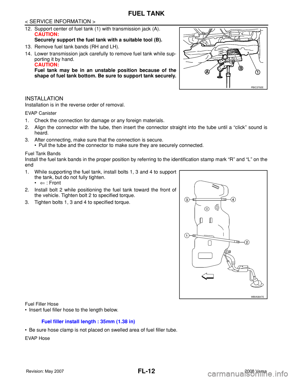
12. Support center of fuel tank (1) with transmission jack (A).
CAUTION:
Securely support the fuel tank with a suitable tool (B).
13. Remove fuel tank bands (RH and LH).
14. Lower transmission jack carefully to remove fuel tank while sup-
porting it by hand.
CAUTION:
Fuel tank may be in an unstable position because of the
shape of fuel tank bottom. Be sure to support tank securely.
INSTALLATION
Installation is in the reverse order of removal.
EVAP Canister
1. Check the connection for damage or any foreign materials.
2. Align the connector with the tube, then insert the connector straight into the tube until a “click” sound is
heard.
3. After connecting, make sure that the connection is secure.
• Pull the tube and the connector to make sure they are securely connected.
Fuel Tank Bands
Install the fuel tank bands in the proper position by referring to the identification stamp mark “R” and “L” on the
end
1. While supporting the fuel tank, install bolts 1, 3 and 4 to support
the tank, but do not fully tighten.
• ⇐ : Front
2. Install bolt 2 while positioning the fuel tank toward the front of
the vehicle. Tighten bolt 2 to specified torque.
3. Tighten bolts 1, 3 and 4 to specified torque.
Fuel Filler Hose
• Insert fuel filler hose to the length below.
• Be sure hose clamp is not placed on swelled area of fuel filler tube.
EVAP Hose
PBIC3792E
WBIA0847E
Fuel filler install length : 35mm (1.38 in)
Page 1842 of 2771
FSU-8
< SERVICE INFORMATION >
FRONT SUSPENSION ASSEMBLY
3. Put a mark on base line of the tread (rear side) of both tires at
the same height of hub center. These are measuring points.
4. Measure distance “A” (rear side).
5. Push vehicle slowly ahead to rotate wheels 180 degrees (1/2
turn).
CAUTION:
If wheels have rotated more than 180 degrees (1/2 turn), try
the above procedure again from the beginning. Never push
vehicle backward.
6. Measure distance “B” (front side).
7. Use the formula below to calculate total toe-in.
• If the total toe-in is outside the specification, adjust toe-in by varying the length of between steering
outer socket and inner socket.
AFA050
SFA234AC
Total toe-in = A - B
For total toe-in specification, refer to FSU-16, "
Wheel Alignment (Unladen*)" .
Page 1856 of 2771

PRECAUTIONS
GI-5
< SERVICE INFORMATION >
C
D
E
F
G
H
I
J
K
L
MB
GI
N
O
P
Precaution for Multiport Fuel Injection System or Engine Control SystemINFOID:0000000001702427
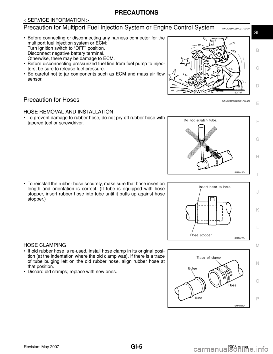
• Before connecting or disconnecting any harness connector for the
multiport fuel injection system or ECM:
Turn ignition switch to “OFF” position.
Disconnect negative battery terminal.
Otherwise, there may be damage to ECM.
• Before disconnecting pressurized fuel line from fuel pump to injec-
tors, be sure to release fuel pressure.
• Be careful not to jar components such as ECM and mass air flow
sensor.
Precaution for HosesINFOID:0000000001702428
HOSE REMOVAL AND INSTALLATION
• To prevent damage to rubber hose, do not pry off rubber hose with
tapered tool or screwdriver.
• To reinstall the rubber hose securely, make sure that hose insertion
length and orientation is correct. (If tube is equipped with hose
stopper, insert rubber hose into tube until it butts up against hose
stopper.)
HOSE CLAMPING
• If old rubber hose is re-used, install hose clamp in its original posi-
tion (at the indentation where the old clamp was). If there is a trace
of tube bulging left on the old rubber hose, align rubber hose at
that position.
• Discard old clamps; replace with new ones.
SGI787
SMA019D
SMA020D
SMA021D
Page 1897 of 2771
GI-46
< SERVICE INFORMATION >
IDENTIFICATION INFORMATION
CVT NUMBER
DimensionsINFOID:0000000001702457
Unit: mm (in)
Wheels & TiresINFOID:0000000001702458
LAIA0074E
Overall length Hatchback: 4,295 (169.1) Sedan: 4470 (176)
Overall width1,694.2 (66.7)
Overall height1,534.1 (60.4)
Front tread1,480 (58.3)
Rear tread1,485 (58.5)
Wheelbase2,599.9 (102.4)
Road wheel
Size15 x 5.5 JJ
Offset mm (in) 40 (1.57)
Tire size
Conventional185/65 R15
Spar eT125/70D15
Page 2305 of 2771
TRANSAXLE ASSEMBLY
MT-17
< SERVICE INFORMATION >
D
E
F
G
H
I
J
K
L
MA
B
MT
N
O
P
When installing transaxle assembly, be careful not to bring transaxle input shaft into contact with
clutch cover.
• If transaxle is removed from the vehicle, always replace CSC. Refer to CL-11, "
Removal and Installation".
• When installing the transaxle assembly to the engine, install the
bolts as shown.
A: M/T to engine
B: Engine to M/T
• After installation, bleed the air from the clutch hydraulic system. Refer to CL-8, "
Air Bleeding Procedure".
• After installation, check oil level, and check for leaks and loose mechanisms. Refer to MA-21, "
Checking M/
T Oil".
Disassembly and AssemblyINFOID:0000000001703142
COMPONENTS
Case and Housing Components
Bolt No. 1 2
Quantity 3 6
Bolt length “ ” mm (in)60 (2.36) 50 (1.97)
Tightening torque
N·m (kg-m, ft-lb)62.0 (6.3, 46)
PCIB1786E
Page 2516 of 2771

PS-10
< SERVICE INFORMATION >
STEERING COLUMN
8. Remove bolt of intermediate shaft (upper side), and then remove intermediate shaft from steering column
assembly.
9. Remove steering column assembly mounting nuts, and then remove steering column assembly from vehi-
cle.
10. Remove bolt of intermediate shaft (lower side), and then remove intermediate shaft from vehicle.
11. Remove screws of bracket and EPS control unit, and then remove bracket and EPS control unit from
steering column assembly.
INSPECTION AFTER REMOVAL
• Check each part of steering column assembly, EPS control unit and intermediate shaft for damage and .
replace as necessary.
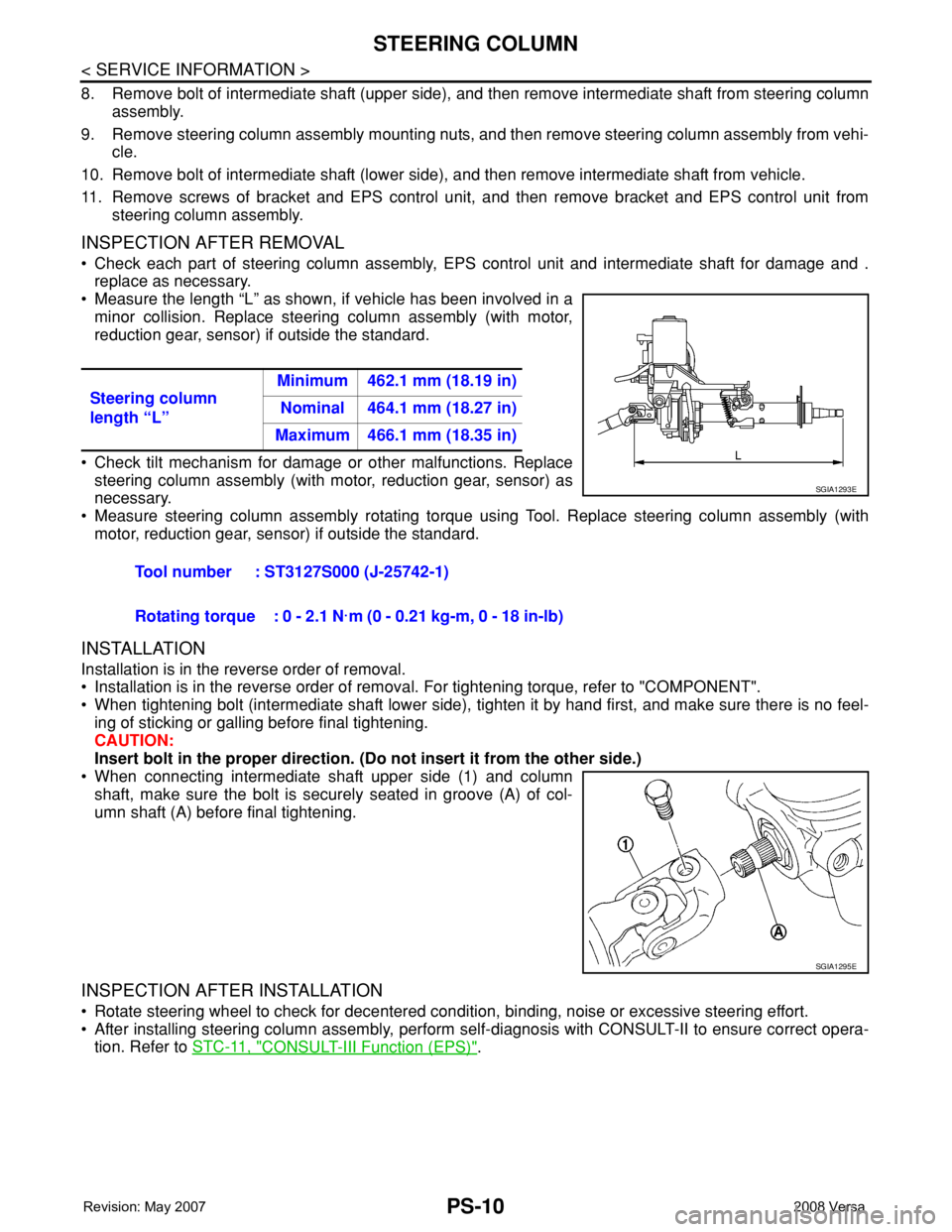
• Measure the length “L” as shown, if vehicle has been involved in a
minor collision. Replace steering column assembly (with motor,
reduction gear, sensor) if outside the standard.
• Check tilt mechanism for damage or other malfunctions. Replace
steering column assembly (with motor, reduction gear, sensor) as
necessary.
• Measure steering column assembly rotating torque using Tool. Replace steering column assembly (with
motor, reduction gear, sensor) if outside the standard.
INSTALLATION
Installation is in the reverse order of removal.
• Installation is in the reverse order of removal. For tightening torque, refer to "COMPONENT".
• When tightening bolt (intermediate shaft lower side), tighten it by hand first, and make sure there is no feel-
ing of sticking or galling before final tightening.
CAUTION:
Insert bolt in the proper direction. (Do not insert it from the other side.)
• When connecting intermediate shaft upper side (1) and column
shaft, make sure the bolt is securely seated in groove (A) of col-
umn shaft (A) before final tightening.
INSPECTION AFTER INSTALLATION
• Rotate steering wheel to check for decentered condition, binding, noise or excessive steering effort.
• After installing steering column assembly, perform self-diagnosis with CONSULT-II to ensure correct opera-
tion. Refer to STC-11, "
CONSULT-III Function (EPS)". Steering column
length “L”Minimum 462.1 mm (18.19 in)
Nominal 464.1 mm (18.27 in)
Maximum 466.1 mm (18.35 in)
Tool number : ST3127S000 (J-25742-1)
Rotating torque : 0 - 2.1 N·m (0 - 0.21 kg-m, 0 - 18 in-lb)
SGIA1293E
SGIA1295E