Page 309 of 2771

REPAIR FOR COMPONENT PARTS
AT-297
< SERVICE INFORMATION >
D
E
F
G
H
I
J
K
L
MA
B
AT
N
O
P
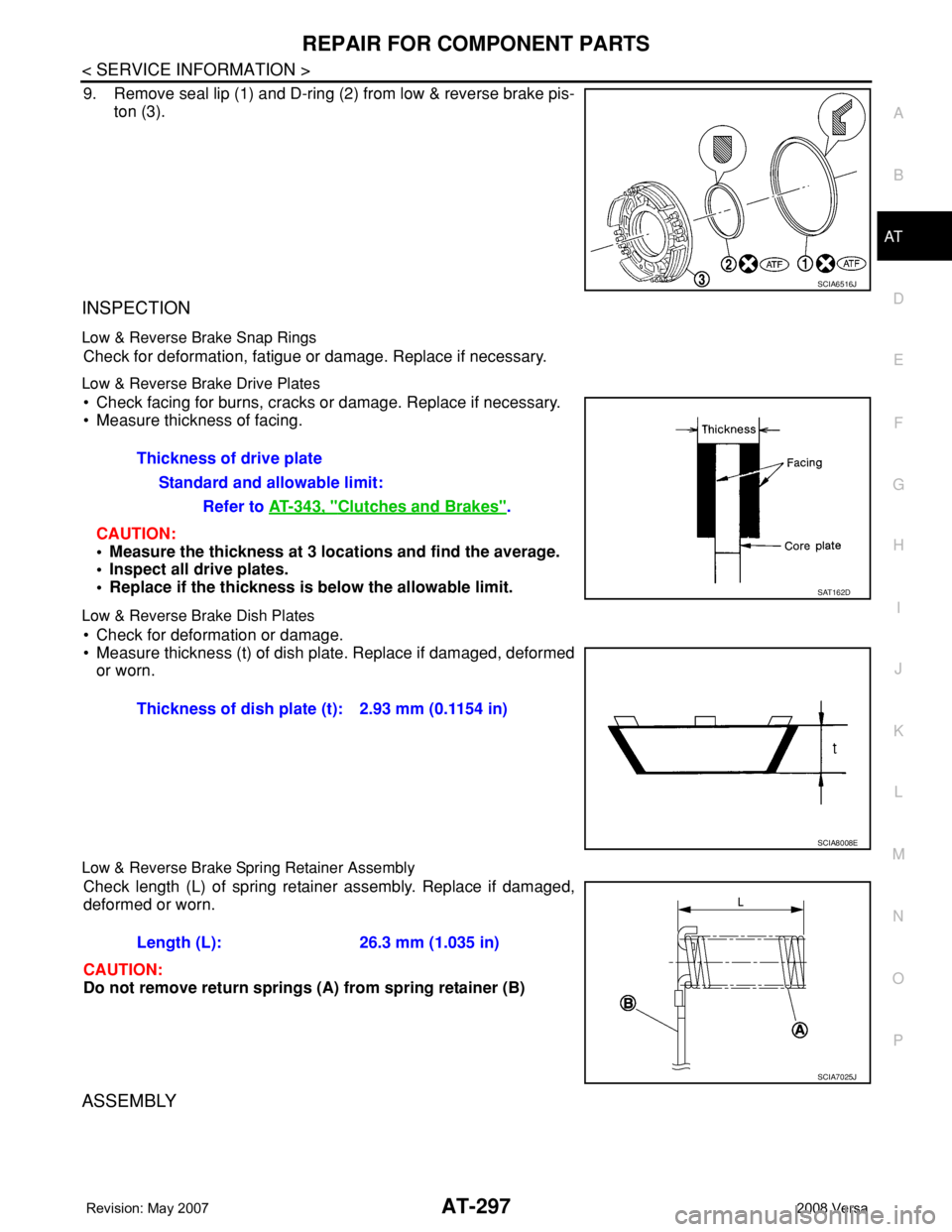
9. Remove seal lip (1) and D-ring (2) from low & reverse brake pis-
ton (3).
INSPECTION
Low & Reverse Brake Snap Rings
Check for deformation, fatigue or damage. Replace if necessary.
Low & Reverse Brake Drive Plates
• Check facing for burns, cracks or damage. Replace if necessary.
• Measure thickness of facing.
CAUTION:
• Measure the thickness at 3 locations and find the average.
• Inspect all drive plates.
• Replace if the thickness is below the allowable limit.
Low & Reverse Brake Dish Plates
• Check for deformation or damage.
• Measure thickness (t) of dish plate. Replace if damaged, deformed
or worn.
Low & Reverse Brake Spring Retainer Assembly
Check length (L) of spring retainer assembly. Replace if damaged,
deformed or worn.
CAUTION:
Do not remove return springs (A) from spring retainer (B)
ASSEMBLY
SCIA6516J
Thickness of drive plate
Standard and allowable limit:
Refer to AT-343, "
Clutches and Brakes".
SAT162D
Thickness of dish plate (t): 2.93 mm (0.1154 in)
SCIA8008E
Length (L): 26.3 mm (1.035 in)
SCIA7025J
Page 322 of 2771
AT-310
< SERVICE INFORMATION >
REPAIR FOR COMPONENT PARTS
9. Remove spring retainer (1), OD servo return spring (2), band
servo piston (3) and band servo thrust washer (4) from band
servo piston stem (5).
10. Remove O-ring (1) from servo piston retainer (2).
11. Remove D-rings from band servo piston.
INSPECTION
Pistons, Retainers and Piston Stem
Check the sliding surfaces for damage or excessive wear. Replace if necessary.
Return Springs
• Check each return spring for damage or deformation. Also mea-
sure free length. Refer to AT-345, "
Band Servo".
• Replace springs if deformed or fatigued.
ASSEMBLY
SCIA7054E
SCIA7967E
SCIA3688E
SAT138D
Page 331 of 2771
ASSEMBLY
AT-319
< SERVICE INFORMATION >
D
E
F
G
H
I
J
K
L
MA
B
AT
N
O
P
8. Install return spring (2) on parking shaft (3) and parking pawl (1)
using a flat-bladed screwdriver.
Adjustment (1)INFOID:0000000001703392
DIFFERENTIAL SIDE BEARING PRELOAD
1. Select proper thickness of differential side bearing adjusting shim using the following procedures.
a. Install differential side bearing outer race without differential side
bearing adjusting shim on transaxle case.
CAUTION:
Apply ATF to differential side bearing outer race.
b. Install differential side bearing outer race on converter housing.
CAUTION:
Apply ATF to differential side bearing outer race.
c. Place final drive assembly on transaxle case.
d. Tighten converter housing fitting bolts (1) and (2) to the specified
torque. Refer to AT-313, "
Final Drive".
SCIA6996E
SAT947DA
Bolt 1 2
Bolt length
[mm (in)]
32.8 (1.291) 40 (1.57)
Number of bolts 10 10
SCIA7970E
Page 348 of 2771
AT-336
< SERVICE INFORMATION >
ASSEMBLY
18. Install O-ring on differential oil port of transaxle case.
19. Apply locking sealant (loctite #518) to transaxle case as shown
in the figure.
: Inside of transaxle case
CAUTION:
Completely remove all moisture, oil and old sealant, etc.
from the transaxle case and converter housing mating sur-
faces.
20. Install converter housing on transaxle case.
21. Install bracket on converter housing.
22. Tighten converter housing fitting bolts (1) and (2) to the specified
torque. Refer to AT-230, "
Component".
23. Install plug or speedometer pinion according to the following
procedures.
a. With ABS
i. Install O-ring (3) to plug (1).
ii. Install plug (1) to converter housing (2).
: Bolt (1)
SCIA3281E
“A”: 3 - 5 mm (0.12 - 0.20 in)
“B”: 8 mm (0.31 in) R
“C”: 1.5 mm (0.059 in) dia.
“D”: 4 mm (0.16 in)
SCIA7089E
Bolt 1 2
Bolt length
[mm (in)]
32.8 (1.291) 40 (1.57)
Number of bolts 10 10
SCIA7970E
SCIA7747E
Page 350 of 2771
AT-338
< SERVICE INFORMATION >
ASSEMBLY
b. Insert manual valve into control valve assembly.
CAUTION:
Be careful not to drop manual valve.
c. Set manual shaft in “N” position.
d. Install control valve assembly on transaxle case while aligning
manual valve (2) with manual plate (1).
e. Install terminal body (2) into transaxle case by pushing it.
f. Install snap ring (1) to terminal body (2).
g. Tighten bolts A, B and C to the specified torque. Refer to AT-230, "
Component".
Bolt length, number and location:
28. Install oil pan.
a. Attach magnets on oil pan.
SCIA3999E
SCIA7090E
SCIA6030J
Bolt symbol A B C
Bolt length “ ” [mm (in)]
40.0 mm
(1.575 in)33.0 mm
(1.299 in)43.5 mm
(1.713 in)
Number of bolts 5 6 2
SCIA5911J
Page 355 of 2771

SERVICE DATA AND SPECIFICATIONS (SDS)
AT-343
< SERVICE INFORMATION >
D
E
F
G
H
I
J
K
L
MA
B
AT
N
O
P
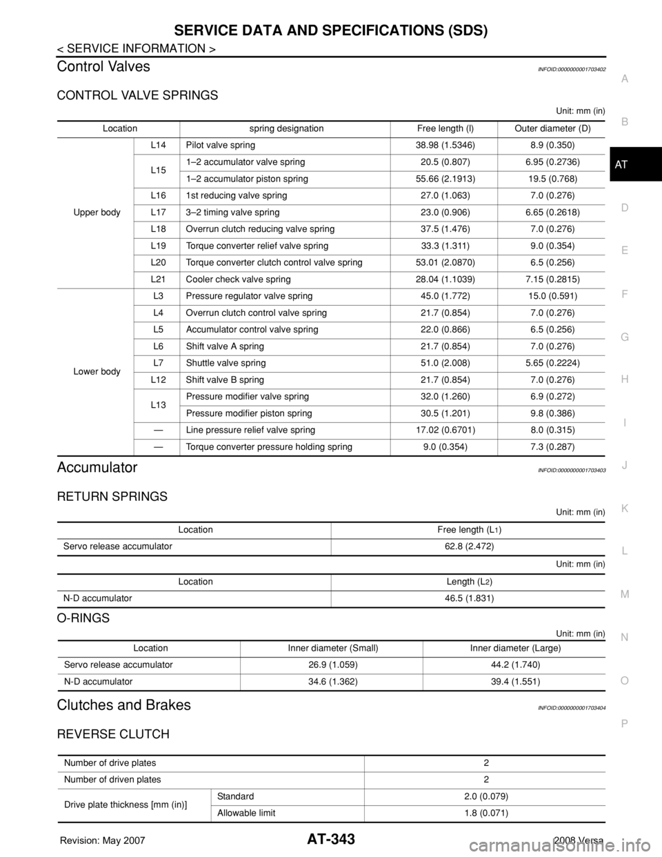
Control ValvesINFOID:0000000001703402
CONTROL VALVE SPRINGS
Unit: mm (in)
AccumulatorINFOID:0000000001703403
RETURN SPRINGS
Unit: mm (in)
Unit: mm (in)
O-RINGS
Unit: mm (in)
Clutches and BrakesINFOID:0000000001703404
REVERSE CLUTCH
Location spring designation Free length (l) Outer diameter (D)
Upper bodyL14 Pilot valve spring 38.98 (1.5346) 8.9 (0.350)
L151–2 accumulator valve spring 20.5 (0.807) 6.95 (0.2736)
1–2 accumulator piston spring 55.66 (2.1913) 19.5 (0.768)
L16 1st reducing valve spring 27.0 (1.063) 7.0 (0.276)
L17 3–2 timing valve spring 23.0 (0.906) 6.65 (0.2618)
L18 Overrun clutch reducing valve spring 37.5 (1.476) 7.0 (0.276)
L19 Torque converter relief valve spring 33.3 (1.311) 9.0 (0.354)
L20 Torque converter clutch control valve spring 53.01 (2.0870) 6.5 (0.256)
L21 Cooler check valve spring 28.04 (1.1039) 7.15 (0.2815)
Lower bodyL3 Pressure regulator valve spring 45.0 (1.772) 15.0 (0.591)
L4 Overrun clutch control valve spring 21.7 (0.854) 7.0 (0.276)
L5 Accumulator control valve spring 22.0 (0.866) 6.5 (0.256)
L6 Shift valve A spring 21.7 (0.854) 7.0 (0.276)
L7 Shuttle valve spring 51.0 (2.008) 5.65 (0.2224)
L12 Shift valve B spring 21.7 (0.854) 7.0 (0.276)
L13Pressure modifier valve spring 32.0 (1.260) 6.9 (0.272)
Pressure modifier piston spring 30.5 (1.201) 9.8 (0.386)
— Line pressure relief valve spring 17.02 (0.6701) 8.0 (0.315)
— Torque converter pressure holding spring 9.0 (0.354) 7.3 (0.287)
Location Free length (L1)
Servo release accumulator 62.8 (2.472)
Location Length (L2)
N-D accumulator46.5 (1.831)
Location Inner diameter (Small) Inner diameter (Large)
Servo release accumulator 26.9 (1.059) 44.2 (1.740)
N-D accumulator 34.6 (1.362) 39.4 (1.551)
Number of drive plates2
Number of driven plates2
Drive plate thickness [mm (in)]Standard 2.0 (0.079)
Allowable limit 1.8 (0.071)
Page 357 of 2771

SERVICE DATA AND SPECIFICATIONS (SDS)
AT-345
< SERVICE INFORMATION >
D
E
F
G
H
I
J
K
L
MA
B
AT
N
O
P
Final DriveINFOID:0000000001703405
DIFFERENTIAL SIDE GEAR CLEARANCE
BEARING PRELOAD
TURNING TORQUE
Planetary CarrierINFOID:0000000001703406
Oil PumpINFOID:0000000001703407
Input ShaftINFOID:0000000001703408
SEAL RING CLEARANCE
SEAL RING
Unit: mm (in)
Reduction Pinion GearINFOID:0000000001703409
TURNING TORQUE
Band ServoINFOID:0000000001703410
RETURN SPRINGS
Unit: mm (in)
Clearance between side gear and differential case with washer [mm (in)] 0.1 - 0.2 (0.004 - 0.008)
Differential side bearing preload mm (in) 0.05 - 0.09 (0.0020 - 0.0035)
Turning torque of final drive assembly N-m (kg-cm, in-lb) 0.68 - 1.26 (7.0 - 13.0, 6.0 - 11.0)
Clearance between planetary carrier and pinion washer [mm (in)]Standard 0.15 - 0.70 (0.0059 - 0.0276)
Allowable limit 0.80 (0.0315)
Oil pump side clearance0.02 - 0.04 (0.0008 - 0.0016)
Clearance between oil pump housing and outer gear [mm (in)]Standard 0.08 - 0.15 (0.0031 - 0.0059)
Allowable limit 0.15 (0.0059)
Oil pump cover seal ring clearance [mm (in)]Standard 0.10 - 0.25 (0.0039 - 0.0098)
Allowable limit 0.25 (0.0098)
Input shaft seal ring clearance [mm (in)]Standard 0.08 - 0.23 (0.0031 - 0.0091)
Allowable limit 0.23 (0.091)
Outer diameter Inner diameter Width
24 (0.94) 20.4 (0.803) 1.97 (0.0776)
Turning torque of reduction pinion gear [N·m (kg-m, in-lb)] 0.11 - 0.69 (0.01 - 0.07, 1 - 6)
Return spring Free length
2nd servo return spring 32.5 (1.280)
OD servo return spring 38.52 (1.5165)
Page 682 of 2771
BL-248
< SERVICE INFORMATION >
BODY REPAIR
Sedan
DESCRIPTION
• All dimensions indicated in the figures are actual.
• When using a tracking gauge, adjust both pointers to equal length. Then check the pointers and gauge itself
to make sure there is no free play.
• When a measuring tape is used, check to be sure there is no elongation, twisting or bending.
• Measurements should be taken at the center of the mounting holes.
• An asterisk (*) following the value at the measuring point indicates that the measuring point on the other side
is symmetrically the same value.
• The coordinates of the measurement points are the distances measured from the standard line of ″X″, ″Y″
and ″Z″.
LIIA2882E