Page 1691 of 2771
EM-14
< SERVICE INFORMATION >
DRIVE BELTS
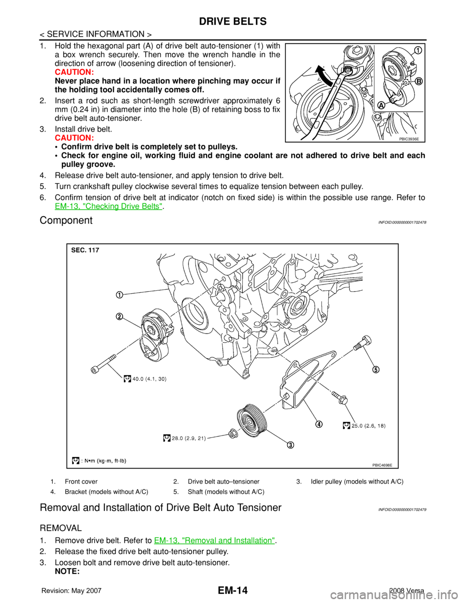
1. Hold the hexagonal part (A) of drive belt auto-tensioner (1) with
a box wrench securely. Then move the wrench handle in the
direction of arrow (loosening direction of tensioner).
CAUTION:
Never place hand in a location where pinching may occur if
the holding tool accidentally comes off.
2. Insert a rod such as short-length screwdriver approximately 6
mm (0.24 in) in diameter into the hole (B) of retaining boss to fix
drive belt auto-tensioner.
3. Install drive belt.
CAUTION:
• Confirm drive belt is completely set to pulleys.
• Check for engine oil, working fluid and engine coolant are not adhered to drive belt and each
pulley groove.
4. Release drive belt auto-tensioner, and apply tension to drive belt.
5. Turn crankshaft pulley clockwise several times to equalize tension between each pulley.
6. Confirm tension of drive belt at indicator (notch on fixed side) is within the possible use range. Refer to
EM-13, "
Checking Drive Belts".
ComponentINFOID:0000000001702478
Removal and Installation of Drive Belt Auto TensionerINFOID:0000000001702479
REMOVAL
1. Remove drive belt. Refer to EM-13, "Removal and Installation".
2. Release the fixed drive belt auto-tensioner pulley.
3. Loosen bolt and remove drive belt auto-tensioner.
NOTE:
PBIC3936E
1. Front cover 2. Drive belt auto–tensioner 3. Idler pulley (models without A/C)
4. Bracket (models without A/C) 5. Shaft (models without A/C)
PBIC4698E
Page 1730 of 2771
CAMSHAFT
EM-53
< SERVICE INFORMATION >
C
D
E
F
G
H
I
J
K
L
MA
EM
N
P O
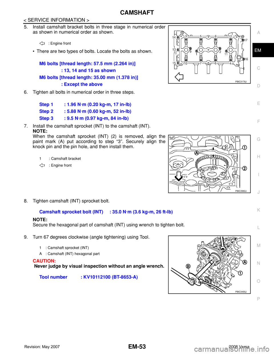
5. Install camshaft bracket bolts in three stage in numerical order
as shown in numerical order as shown.
• There are two types of bolts. Locate the bolts as shown.
6. Tighten all bolts in numerical order in three steps.
7. Install the camshaft sprocket (INT) to the camshaft (INT).
NOTE:
When the camshaft sprocket (INT) (2) is removed, align the
paint mark (A) put according to step “3”. Securely align the
knock pin and the pin hole, and then install them.
8. Tighten camshaft (INT) sprocket bolt.
NOTE:
Secure the hexagonal part of camshaft (INT) using wrench to tighten bolt.
9. Turn 67 degrees clockwise (angle tightening) using Tool.
CAUTION:
Never judge by visual inspection without an angle wrench.
: Engine front
M6 bolts [thread length: 57.5 mm (2.264 in)]
: 13, 14 and 15 as shown
M6 bolts [thread length: 35.00 mm (1.378 in)]
: Except the above
Step 1 : 1.96 N·m (0.20 kg-m, 17 in-lb)
Step 2 : 5.88 N·m (0.60 kg-m, 52 in-lb)
Step 3 : 9.5 N·m (0.97 kg-m, 84 in-lb)
1 : Camshaft bracket
: Engine front
PBIC3176J
PBIC3992J
Camshaft sprocket bolt (INT) : 35.0 N·m (3.6 kg-m, 26 ft-lb)
1 : Camshaft sprocket (INT)
A : Camshaft (INT) hexagonal part
Tool number : KV10112100 (BT-8653-A)
PBIC3455J
Page 1773 of 2771
EM-96
< SERVICE INFORMATION >
CYLINDER BLOCK
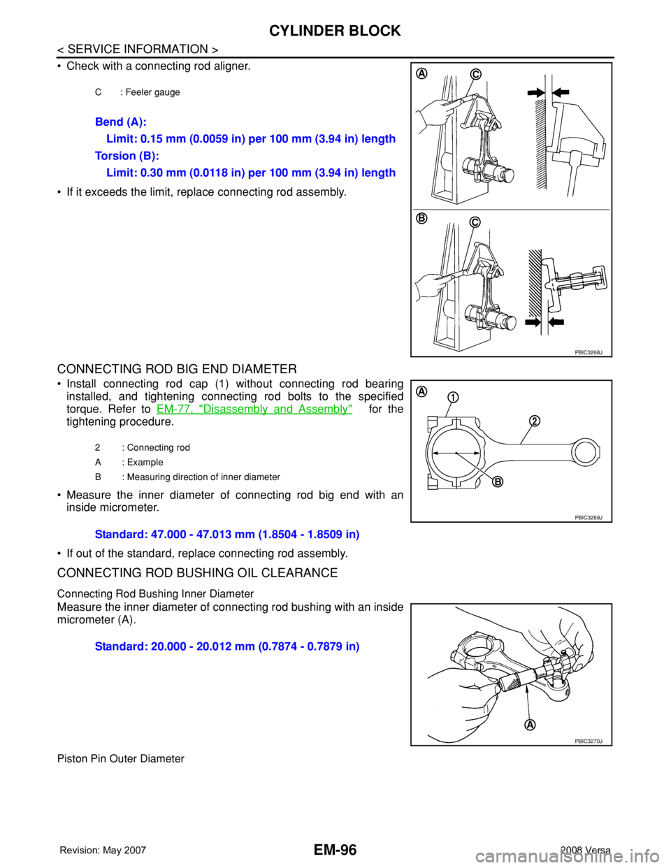
• Check with a connecting rod aligner.
• If it exceeds the limit, replace connecting rod assembly.
CONNECTING ROD BIG END DIAMETER
• Install connecting rod cap (1) without connecting rod bearing
installed, and tightening connecting rod bolts to the specified
torque. Refer to EM-77, "
Disassembly and Assembly" for the
tightening procedure.
• Measure the inner diameter of connecting rod big end with an
inside micrometer.
• If out of the standard, replace connecting rod assembly.
CONNECTING ROD BUSHING OIL CLEARANCE
Connecting Rod Bushing Inner Diameter
Measure the inner diameter of connecting rod bushing with an inside
micrometer (A).
Piston Pin Outer Diameter
C : Feeler gauge
Bend (A):
Limit: 0.15 mm (0.0059 in) per 100 mm (3.94 in) length
To r s i o n ( B ) :
Limit: 0.30 mm (0.0118 in) per 100 mm (3.94 in) length
PBIC3268J
2 : Connecting rod
A : Example
B : Measuring direction of inner diameter
Standard: 47.000 - 47.013 mm (1.8504 - 1.8509 in)
PBIC3269J
Standard: 20.000 - 20.012 mm (0.7874 - 0.7879 in)
PBIC3270J
Page 1782 of 2771
SERVICE DATA AND SPECIFICATIONS (SDS)
EM-105
< SERVICE INFORMATION >
C
D
E
F
G
H
I
J
K
L
MA
EM
N
P O
Unit: mm (in)
VA LV E
Va l v e Ti m i n g
Unit: degree
( ): Valve timing control “ON”
Valve Dimensions
Unit: mm (in)
Items Standard Limit
Head surface distortion — 0.1 (0.004)
Normal cylinder head height “H” 130.9 (5.15) —
PBIC0924E
Valve timing
abcde f
212 224 -8 (32) 52 (12) 7 25
PBIC4542E
Valve head diameter “D”Intake 33.8 - 34.1 (1.331 - 1.343)
Exhaust 27.6 - 27.9 (1.087 - 1.098)
Valve length “L”Intake 106.27 (4.184)
Exhaust 105.26 (4.144)
SEM188A
Page 1784 of 2771
SERVICE DATA AND SPECIFICATIONS (SDS)
EM-107
< SERVICE INFORMATION >
C
D
E
F
G
H
I
J
K
L
MA
EM
N
P O Va l v e Sp r i n g
Valve Lifter
Unit: mm (in)
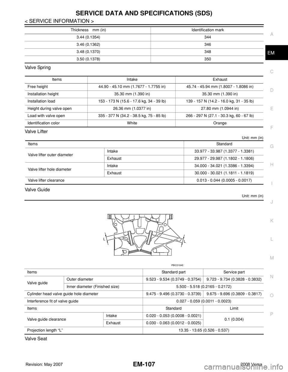
Valve Guide
Unit: mm (in)
Valve Seat
3.44 (0.1354) 344
3.46 (0.1362) 346
3.48 (0.1370) 348
3.50 (0.1378) 350 Thickness mm (in) Identification mark
Items Intake Exhaust
Free height 44.90 - 45.10 mm (1.7677 - 1.7755 in) 45.74 - 45.94 mm (1.8007 - 1.8086 in)
Installation height 35.30 mm (1.390 in) 35.30 mm (1.390 in)
Installation load 153 - 173 N (15.6 - 17.6 kg, 34 - 39 lb) 139 - 157 N (14.2 - 16.0 kg, 31 - 35 lb)
Height during valve open 26.36 mm (1.0377 in) 27.80 mm (1.0944 in)
Load with valve open 335 - 377 N (34.2 - 38.5 kg, 75 - 85 lb) 266 - 297 N (27.1 - 30.3 kg, 60 - 67 lb)
Identification color White Orange
ItemsStandard
Valve lifter outer diameterIntake 33.977 - 33.987 (1.3377 - 1.3381)
Exhaust 29.977 - 29.987 (1.1802 - 1.1806)
Valve lifter hole diameterIntake 34.000 - 34.021 (1.3386 - 1.3394)
Exhaust 30.000 - 30.021 (1.1811 - 1.1819)
Valve lifter clearance0.013 - 0.044 (0.0005 - 0.0017)
Items Standard part Service part
Va l v e g u i d eOuter diameter 9.523 - 9.534 (0.3749 - 0.3754) 9.723 - 9.734 (0.3828 - 0.3832)
Inner diameter (Finished size) 5.500 - 5.518 (0.2165 - 0.2172)
Cylinder head valve guide hole diameter 9.475 - 9.496 (0.3730 - 0.3739) 9.675 - 9.696 (0.3809 - 0.3817)
Interference fit of valve guide 0.027 - 0.059 (0.0011 - 0.0023)
ItemsStandard Limit
Valve guide clearanceIntake 0.020 - 0.053 (0.0008 - 0.0021)
0.1 (0.004)
Exhaust 0.030 - 0.063 (0.0012 - 0.0025)
Projection length “L” 13.35 - 13.65 (0.526 - 0.537)
PBIC0184E
Page 1810 of 2771
FAX-14
< SERVICE INFORMATION >
FRONT DRIVE SHAFT
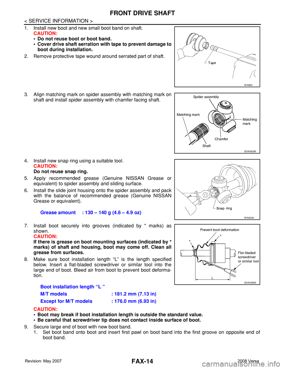
1. Install new boot and new small boot band on shaft.
CAUTION:
• Do not reuse boot or boot band.
• Cover drive shaft serration with tape to prevent damage to
boot during installation.
2. Remove protective tape wound around serrated part of shaft.
3. Align matching mark on spider assembly with matching mark on
shaft and install spider assembly with chamfer facing shaft.
4. Install new snap ring using a suitable tool.
CAUTION:
Do not reuse snap ring.
5. Apply recommended grease (Genuine NISSAN Grease or
equivalent) to spider assembly and sliding surface.
6. Install the slide joint housing onto the spider assembly and pack
with the balance of recommended grease (Genuine NISSAN
Grease or equivalent).
7. Install boot securely into grooves (indicated by * marks) as
shown.
CAUTION:
If there is grease on boot mounting surfaces (indicated by *
marks) of shaft and housing, boot may come off. Clean all
grease from surfaces.
8. Make sure boot installation length “L” is the length specified
below. Insert a flat-bladed screwdriver or similar tool into the
large end of boot. Bleed air from boot to prevent boot deforma-
tion.
CAUTION:
• Boot may break if boot installation length is outside the standard value.
• Be careful that screwdriver tip does not contact inside surface of boot.
9. Secure large end of boot with new boot band.
1. Set boot band onto boot and insert first pawl on boot band into the first groove on opposite end of
boot band.
SFA800
SDIA2629E
Grease amount : 130 – 140 g (4.6 – 4.9 oz) SFA023A
Boot installation length “L ”
M/T models : 181.2 mm (7.13 in)
Except for M/T models : 176.0 mm (6.93 in)
SDIA3285E
Page 1812 of 2771
FAX-16
< SERVICE INFORMATION >
FRONT DRIVE SHAFT
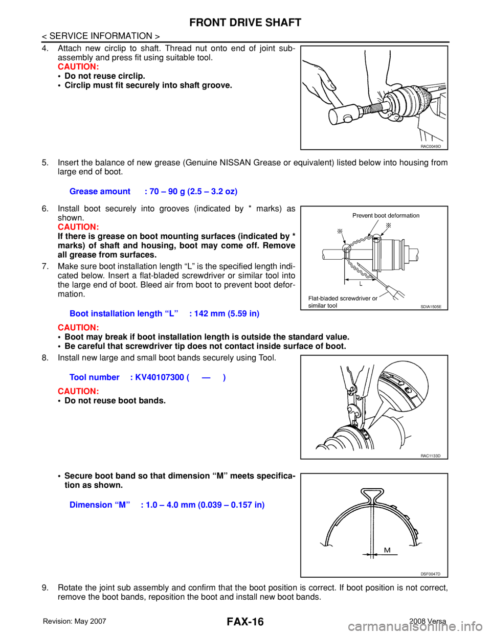
4. Attach new circlip to shaft. Thread nut onto end of joint sub-
assembly and press fit using suitable tool.
CAUTION:
• Do not reuse circlip.
• Circlip must fit securely into shaft groove.
5. Insert the balance of new grease (Genuine NISSAN Grease or equivalent) listed below into housing from
large end of boot.
6. Install boot securely into grooves (indicated by * marks) as
shown.
CAUTION:
If there is grease on boot mounting surfaces (indicated by *
marks) of shaft and housing, boot may come off. Remove
all grease from surfaces.
7. Make sure boot installation length “L” is the specified length indi-
cated below. Insert a flat-bladed screwdriver or similar tool into
the large end of boot. Bleed air from boot to prevent boot defor-
mation.
CAUTION:
• Boot may break if boot installation length is outside the standard value.
• Be careful that screwdriver tip does not contact inside surface of boot.
8. Install new large and small boot bands securely using Tool.
CAUTION:
• Do not reuse boot bands.
• Secure boot band so that dimension “M” meets specifica-
tion as shown.
9. Rotate the joint sub assembly and confirm that the boot position is correct. If boot position is not correct,
remove the boot bands, reposition the boot and install new boot bands.
RAC0049D
Grease amount : 70 – 90 g (2.5 – 3.2 oz)
Boot installation length “L” : 142 mm (5.59 in)
Tool number : KV40107300 ( — )
SDIA1505E
RAC1133D
Dimension “M” : 1.0 – 4.0 mm (0.039 – 0.157 in)
DSF0047D
Page 1816 of 2771
FAX-20
< SERVICE INFORMATION >
FRONT DRIVE SHAFT
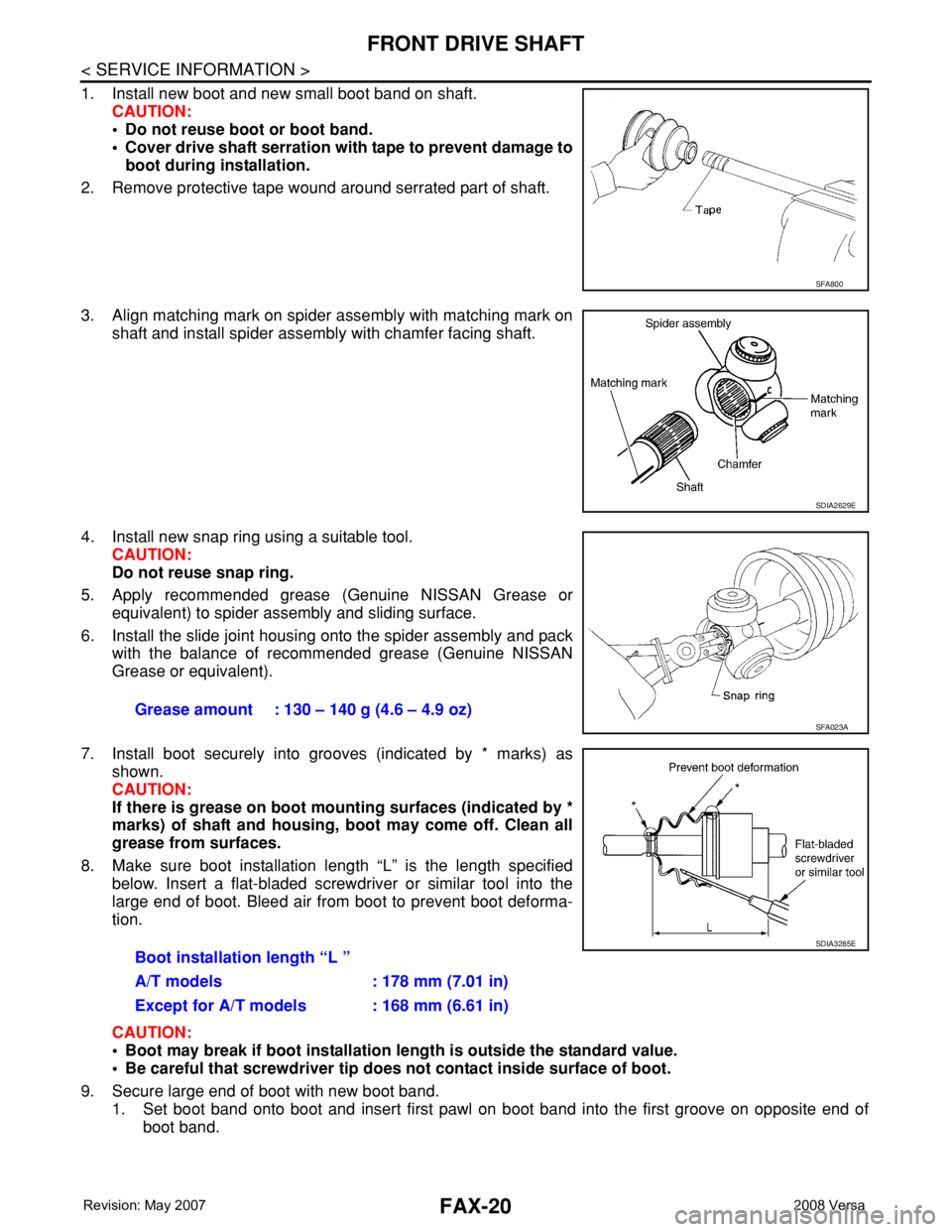
1. Install new boot and new small boot band on shaft.
CAUTION:
• Do not reuse boot or boot band.
• Cover drive shaft serration with tape to prevent damage to
boot during installation.
2. Remove protective tape wound around serrated part of shaft.
3. Align matching mark on spider assembly with matching mark on
shaft and install spider assembly with chamfer facing shaft.
4. Install new snap ring using a suitable tool.
CAUTION:
Do not reuse snap ring.
5. Apply recommended grease (Genuine NISSAN Grease or
equivalent) to spider assembly and sliding surface.
6. Install the slide joint housing onto the spider assembly and pack
with the balance of recommended grease (Genuine NISSAN
Grease or equivalent).
7. Install boot securely into grooves (indicated by * marks) as
shown.
CAUTION:
If there is grease on boot mounting surfaces (indicated by *
marks) of shaft and housing, boot may come off. Clean all
grease from surfaces.
8. Make sure boot installation length “L” is the length specified
below. Insert a flat-bladed screwdriver or similar tool into the
large end of boot. Bleed air from boot to prevent boot deforma-
tion.
CAUTION:
• Boot may break if boot installation length is outside the standard value.
• Be careful that screwdriver tip does not contact inside surface of boot.
9. Secure large end of boot with new boot band.
1. Set boot band onto boot and insert first pawl on boot band into the first groove on opposite end of
boot band.
SFA800
SDIA2629E
Grease amount : 130 – 140 g (4.6 – 4.9 oz) SFA023A
Boot installation length “L ”
A/T models : 178 mm (7.01 in)
Except for A/T models : 168 mm (6.61 in)
SDIA3285E