2008 NISSAN LATIO battery
[x] Cancel search: batteryPage 1959 of 2771
GW-58
< SERVICE INFORMATION >
REAR WINDOW DEFOGGER
OK or NG
OK >> Check condition of harness and connector.
NG >> Replace IPDM E/R. Refer to PG-26, "
Removal and Installation of IPDM E/R" .
Door Mirror Defogger Circuit InspectionINFOID:0000000001704178
1.CHECK FUSE
Check if the following fuse in the fuse block (J/B) is blown.
OK or NG
OK >> GO TO 2.
NG >> If fuse is blown, be sure to eliminate cause of malfunction before installing new fuse.
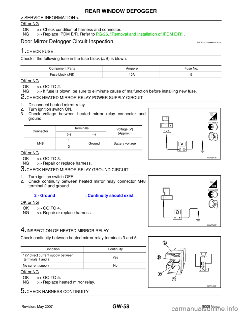
2.CHECK HEATED MIRROR RELAY POWER SUPPLY CIRCUIT
1. Disconnect heated mirror relay.
2. Turn ignition switch ON.
3. Check voltage between heated mirror relay connector and
ground.
OK or NG
OK >> GO TO 3.
NG >> Repair or replace harness.
3.CHECK HEATED MIRROR RELAY GROUND CIRCUIT
1. Turn ignition switch OFF.
2. Check continuity between heated mirror relay connector M48
terminal 2 and ground.
OK or NG
OK >> GO TO 4.
NG >> Repair or replace harness.
4.INSPECTION OF HEATED MIRROR RELAY
Check continuity between heated mirror relay terminals 3 and 5.
OK or NG
OK >> GO TO 5.
NG >> Replace heated mirror relay.
5.CHECK HARNESS CONTINUITY
Component Parts Ampere Fuse No.
Fuse block (J/B) 10A 5
ConnectorTe r m i n a l s
Voltage (V)
(Approx.)
(+) (-)
M481
Ground Battery voltage
3
LIIA2647E
2 - Ground : Continuity should exist.
LIIA2646E
Condition Continuity
12V direct current supply between
terminals 1 and 2Ye s
No current supply No
SEF145X
Page 1960 of 2771
REAR WINDOW DEFOGGER
GW-59
< SERVICE INFORMATION >
C
D
E
F
G
H
J
K
L
MA
B
GW
N
O
P
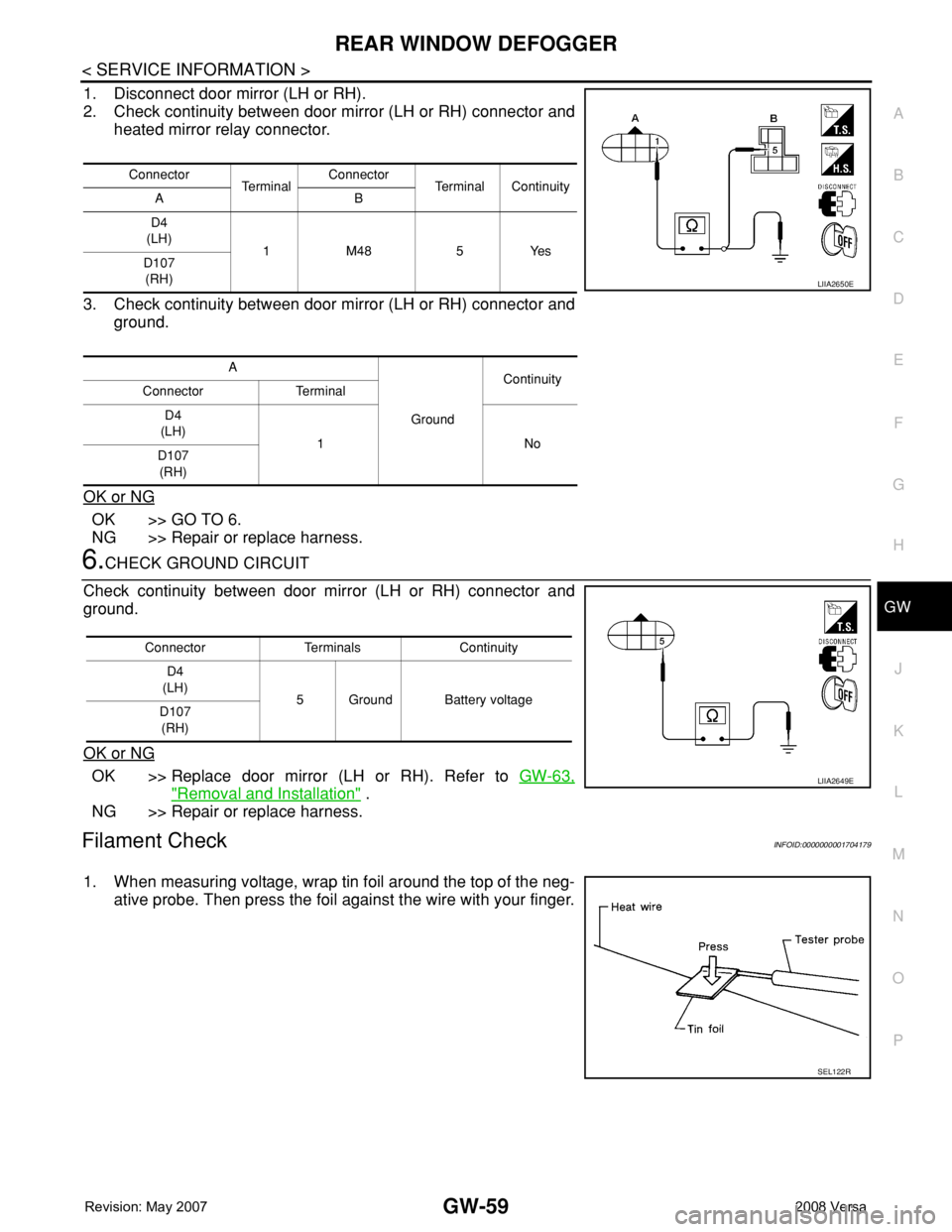
1. Disconnect door mirror (LH or RH).
2. Check continuity between door mirror (LH or RH) connector and
heated mirror relay connector.
3. Check continuity between door mirror (LH or RH) connector and
ground.
OK or NG
OK >> GO TO 6.
NG >> Repair or replace harness.
6.CHECK GROUND CIRCUIT
Check continuity between door mirror (LH or RH) connector and
ground.
OK or NG
OK >> Replace door mirror (LH or RH). Refer to GW-63,
"Removal and Installation" .
NG >> Repair or replace harness.
Filament CheckINFOID:0000000001704179
1. When measuring voltage, wrap tin foil around the top of the neg-
ative probe. Then press the foil against the wire with your finger.
Connector
Te r m i n a lConnector
Terminal Continuity
AB
D4
(LH)
1 M48 5 Yes
D107
(RH)
A
GroundContinuity
Connector Terminal
D4
(LH)
1No
D107
(RH)
LIIA2650E
Connector Terminals Continuity
D4
(LH)
5 Ground Battery voltage
D107
(RH)
LIIA2649E
SEL122R
Page 1961 of 2771
GW-60
< SERVICE INFORMATION >
REAR WINDOW DEFOGGER
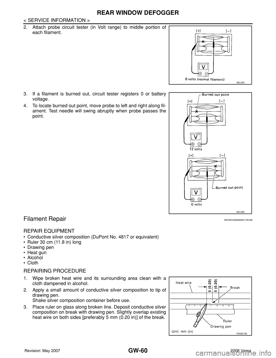
2. Attach probe circuit tester (in Volt range) to middle portion of
each filament.
3. If a filament is burned out, circuit tester registers 0 or battery
voltage.
4. To locate burned out point, move probe to left and right along fil-
ament. Test needle will swing abruptly when probe passes the
point.
Filament RepairINFOID:0000000001704180
REPAIR EQUIPMENT
• Conductive silver composition (DuPont No. 4817 or equivalent)
• Ruler 30 cm (11.8 in) long
• Drawing pen
• Heat gun
• Alcohol
• Cloth
REPAIRING PROCEDURE
1. Wipe broken heat wire and its surrounding area clean with a
cloth dampened in alcohol.
2. Apply a small amount of conductive silver composition to tip of
drawing pen.
Shake silver composition container before use.
3. Place ruler on glass along broken line. Deposit conductive silver
composition on break with drawing pen. Slightly overlap existing
heat wire on both sides [preferably 5 mm (0.20 in)] of the break.
SEL263
SEL265
PIIA0215E
Page 1968 of 2771
IP-2
< PRECAUTION >
PRECAUTIONS
PRECAUTION
PRECAUTIONS
Precaution for Supplemental Restraint System (SRS) "AIR BAG" and "SEAT BELT
PRE-TENSIONER"
INFOID:0000000001704244
The Supplemental Restraint System such as “AIR BAG” and “SEAT BELT PRE-TENSIONER”, used along
with a front seat belt, helps to reduce the risk or severity of injury to the driver and front passenger for certain
types of collision. This system includes seat belt switch inputs and dual stage front air bag modules. The SRS
system uses the seat belt switches to determine the front air bag deployment, and may only deploy one front
air bag, depending on the severity of a collision and whether the front occupants are belted or unbelted.
Information necessary to service the system safely is included in the SR and SB section of this Service Man-
ual.
WARNING:
• To avoid rendering the SRS inoperative, which could increase the risk of personal injury or death in
the event of a collision which would result in air bag inflation, all maintenance must be performed by
an authorized NISSAN/INFINITI dealer.
• Improper maintenance, including incorrect removal and installation of the SRS, can lead to personal
injury caused by unintentional activation of the system. For removal of Spiral Cable and Air Bag
Module, see the SR section.
• Do not use electrical test equipment on any circuit related to the SRS unless instructed to in this
Service Manual. SRS wiring harnesses can be identified by yellow and/or orange harnesses or har-
ness connectors.
PrecautionINFOID:0000000001704245
• Disconnect both battery terminals in advance.
• Disconnect air bag system line in advance.
• Never tamper with or force air bag lid open, as this may adversely affect air bag performance.
• Be careful not to scratch pad and other parts.
• When removing or disassembling any part, be careful not to damage or deform it. Protect parts which may
get in the way with cloth.
• When removing parts, protect parts by wrapping tools with vinyl or tape.
• Keep removed parts protected with cloth.
• If a clip is deformed or damaged, replace it.
• If an non-reusable part is removed, replace it with a new one.
• Tighten bolts and nuts firmly to the specified torque.
• After re-assembly has been completed, make sure each part functions correctly.
• Remove stains in the following way.
Water-soluble stains:
Dip a soft cloth in warm water, and then squeeze it tightly. After wiping the stain, wipe with a soft dry cloth.
Oil stain:
Dissolve a synthetic detergent in warm water (density of 2 to 3% or less), dip the cloth, then clean off the stain
with the cloth. Next, dip the cloth in fresh water and squeeze it tightly. Then clean off the detergent completely.
Then wipe the area with a soft dry cloth.
• Do not use any organic solvent, such as thinner or benzine.
Page 1977 of 2771
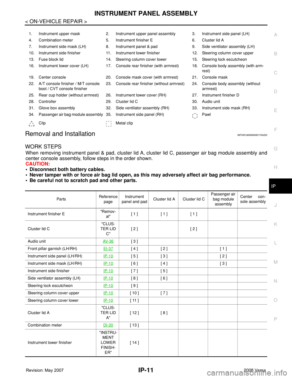
INSTRUMENT PANEL ASSEMBLY
IP-11
< ON-VEHICLE REPAIR >
C
D
E
F
G
H
J
K
L
MA
B
IP
N
O
P
Removal and InstallationINFOID:0000000001704252
WORK STEPS
When removing instrument panel & pad, cluster lid A, cluster lid C, passenger air bag module assembly and
center console assembly, follow steps in the order shown.
CAUTION:
• Disconnect both battery cables.
• Never tamper with or force air bag lid open, as this may adversely affect air bag performance.
• Be careful not to scratch pad and other parts.
1. Instrument upper mask 2. Instrument upper panel assembly 3. Instrument side panel (LH)
4. Combination meter 5. Instrument finisher E 6. Cluster lid A
7. Instrument side mask (LH) 8. Instrument panel & pad 9. Side ventilator assembly (LH)
10. Instrument side finisher 11. Instrument lower finisher 12. Steering column cover upper
13. Fuse block lid 14. Steering column cover lower 15. Steering lock escutcheon
16. Instrument lower cover (LH) 17. Console rear finisher (with armrest) 18. Console body assembly (with arm-
rest)
19. Center console 20. Console mask cover (with armrest) 21. Console mask
22. A/T console finisher / M/T console
boot / CVT console finisher23. Console rear finisher (without armrest) 24. Console body assembly (without
armrest)
25. Rear cup holder (without armrest) 26. Instrument lower cover (RH) 27. Instrument finisher D
28. Controller 29. Cluster lid C 30. Audio unit
31. Glove box assembly 32. Side ventilator assembly (RH) 33. Instrument side mask (RH)
34. Passenger air bag module assembly 35. Instrument side panel (RH) Pawl
Clip Metal clip
PartsReference
pageInstrument
panel and padCluster lid A Cluster lid C Passenger air
bag module
assemblyCenter con-
sole assembly
Instrument finisher E"Remov-
al"[ 1 ] [ 1 ] [ 1 ]
Cluster lid C"CLUS-
TER LID
C"[ 2 ] [ 2 ]
Audio unitAV- 3 6
[ 3 ]
Front pillar garnish (LH/RH)EI-37
[ 4 ] [ 2 ] [ 1 ]
Instrument side panel (LH/RH)IP-10
[ 5 ] [ 3 ] [ 2 ]
Instrument side mask (LH/RH)IP-10
[ 6 ] [ 4 ] [ 3 ]
Instrument side finisherIP-10
[ 7 ] [ 5 ]
Side ventilator assembly (LH)IP-10
[ 8 ] [ 6 ]
Steering lock escutcheonIP-10
[ 9 ]
Steering column cover upperIP-10
[ 10 ] [ 7 ]
Steering column cover lowerIP-10
[ 11 ]
Cluster lid A"CLUS-
TER LID
A"[ 12 ] [ 8 ]
Combination meterDI-20
[ 13 ]
Instrument lower finisher"INSTRU-
MENT
LOWER
FINISH-
ER"[ 14 ]
Page 1996 of 2771
![NISSAN LATIO 2008 Service Repair Manual PRECAUTIONS
LAN-5
< PRECAUTION >[CAN FUNDAMENTAL]
C
D
E
F
G
H
I
J
L
MA
B
LAN
N
O
P
PRECAUTION
PRECAUTIONS
Precautions for Trouble DiagnosisINFOID:0000000001711198
CAUTION:
• Never apply 7.0 V or mor NISSAN LATIO 2008 Service Repair Manual PRECAUTIONS
LAN-5
< PRECAUTION >[CAN FUNDAMENTAL]
C
D
E
F
G
H
I
J
L
MA
B
LAN
N
O
P
PRECAUTION
PRECAUTIONS
Precautions for Trouble DiagnosisINFOID:0000000001711198
CAUTION:
• Never apply 7.0 V or mor](/manual-img/5/57360/w960_57360-1995.png)
PRECAUTIONS
LAN-5
< PRECAUTION >[CAN FUNDAMENTAL]
C
D
E
F
G
H
I
J
L
MA
B
LAN
N
O
P
PRECAUTION
PRECAUTIONS
Precautions for Trouble DiagnosisINFOID:0000000001711198
CAUTION:
• Never apply 7.0 V or more to the measurement terminal.
• Use a tester with open terminal voltage of 7.0 V or less.
• Turn the ignition switch OFF and disconnect the battery cable from the negative terminal when
checking the harness.
Precautions for Harness RepairINFOID:0000000001711199
• Solder the repaired area and wrap tape around the soldered area.
NOTE:
A fray of twisted lines must be within 110 mm (4.33 in).
• Bypass connection is never allowed at the repaired area.
NOTE:
Bypass connection may cause CAN communication error. The
spliced wire becomes separated and the characteristics of twisted
line are lost.
• Replace the applicable harness as an assembly if error is detected on the shield lines of CAN communica-
tion line.
SKIB8766E
SKIB8767E
Page 2000 of 2771
![NISSAN LATIO 2008 Service Repair Manual TROUBLE DIAGNOSIS
LAN-9
< FUNCTION DIAGNOSIS >[CAN FUNDAMENTAL]
C
D
E
F
G
H
I
J
L
MA
B
LAN
N
O
P
TROUBLE DIAGNOSIS
Condition of Error DetectionINFOID:0000000001711205
“U1000” or “U1001” is ind NISSAN LATIO 2008 Service Repair Manual TROUBLE DIAGNOSIS
LAN-9
< FUNCTION DIAGNOSIS >[CAN FUNDAMENTAL]
C
D
E
F
G
H
I
J
L
MA
B
LAN
N
O
P
TROUBLE DIAGNOSIS
Condition of Error DetectionINFOID:0000000001711205
“U1000” or “U1001” is ind](/manual-img/5/57360/w960_57360-1999.png)
TROUBLE DIAGNOSIS
LAN-9
< FUNCTION DIAGNOSIS >[CAN FUNDAMENTAL]
C
D
E
F
G
H
I
J
L
MA
B
LAN
N
O
P
TROUBLE DIAGNOSIS
Condition of Error DetectionINFOID:0000000001711205
“U1000” or “U1001” is indicated on SELF-DIAG RESULTS on CONSULT-III if CAN communication signal is
not transmitted or received between units for 2 seconds or more.
CAN COMMUNICATION SYSTEM ERROR
• CAN communication line open (CAN-H, CAN-L, or both)
• CAN communication line short (ground, between CAN communication lines, other harnesses)
• Error of CAN communication control circuit of the unit connected to CAN communication line
WHEN “U1000” OR “U1001” IS INDICATED EVEN THOUGH CAN COMMUNICATION SYSTEM IS
NORMAL
• Removal/installation of parts: Error may be detected when removing and installing CAN communication unit
and related parts while turning the ignition switch ON. (A DTC except for CAN communication may be
detected.)
• Fuse blown out (removed): CAN communication of the unit may cease.
• Voltage drop: Error may be detected if voltage drops due to discharged battery when turning the ignition
switch ON (Depending on the control unit which carries out CAN communication).
• Error may be detected if the power supply circuit of the control unit, which carries out CAN communication,
malfunctions (Depending on the control unit which carries out CAN communication).
• Error may be detected if reprogramming is not completed normally.
NOTE:
CAN communication system is normal if “U1000” or “U1001” is indicated on SELF-DIAG RESULTS of CON-
SULT-III under the above conditions. Erase the memory of the self-diagnosis of each unit.
Symptom When Error Occurs in CAN Communication SystemINFOID:0000000001711206
In CAN communication system, multiple units mutually transmit and receive signals. Each unit cannot transmit
and receive signals if any error occurs on CAN communication line. Under this condition, multiple control units
related to the root cause malfunction or go into fail-safe mode.
ERROR EXAMPLE
NOTE:
• Each vehicle differs in symptom of each unit under fail-safe mode and CAN communication line wiring.
• Refer to LAN-20, "
Abbreviation List" for the unit abbreviation.
Example: TCM branch line open circuit
SKIB8738E
Unit name Symptom
ECM Engine torque limiting is affected, and shift harshness increases.
BCM Reverse warning chime does not sound.
Page 2007 of 2771
![NISSAN LATIO 2008 Service Repair Manual LAN-16
< BASIC INSPECTION >[CAN FUNDAMENTAL]
DIAGNOSIS AND REPAIR WORKFLOW
• Indication of the combination meter is important to detect the root cause because it is the most obvious to
the customer, NISSAN LATIO 2008 Service Repair Manual LAN-16
< BASIC INSPECTION >[CAN FUNDAMENTAL]
DIAGNOSIS AND REPAIR WORKFLOW
• Indication of the combination meter is important to detect the root cause because it is the most obvious to
the customer,](/manual-img/5/57360/w960_57360-2006.png)
LAN-16
< BASIC INSPECTION >[CAN FUNDAMENTAL]
DIAGNOSIS AND REPAIR WORKFLOW
• Indication of the combination meter is important to detect the root cause because it is the most obvious to
the customer, and it performs CAN communication with many units.
INSPECTION OF VEHICLE CONDITION
Check whether the symptom is reproduced or not.
NOTE:
Do not turn the ignition switch OFF or disconnect the battery cable while reproducing the error. The error may
temporarily correct itself, making it difficult to determine the root cause.
CHECK OF CAN SYSTEM TYPE (HOW TO USE CAN SYSTEM TYPE SPECIFICATION CHART)
Determine CAN system type based on vehicle equipment.
NOTE:
• This chart is used if CONSULT-III does not automatically recognize CAN system type.
• There are two styles for CAN system type specification charts. Depending on the number of available sys-
tem types, either style A or style B may be used.
CAN System Type Specification Chart (Style A)
NOTE:
SKIB8717E