2008 NISSAN LATIO battery
[x] Cancel search: batteryPage 1739 of 2771
EM-62
< SERVICE INFORMATION >
CYLINDER HEAD
CYLINDER HEAD
On-Vehicle ServiceINFOID:0000000001702501
CHECKING COMPRESSION PRESSURE
1. Warm up engine thoroughly. Then, stop it.
2. Release fuel pressure. Refer to EC-78, "
Fuel Pressure Check".
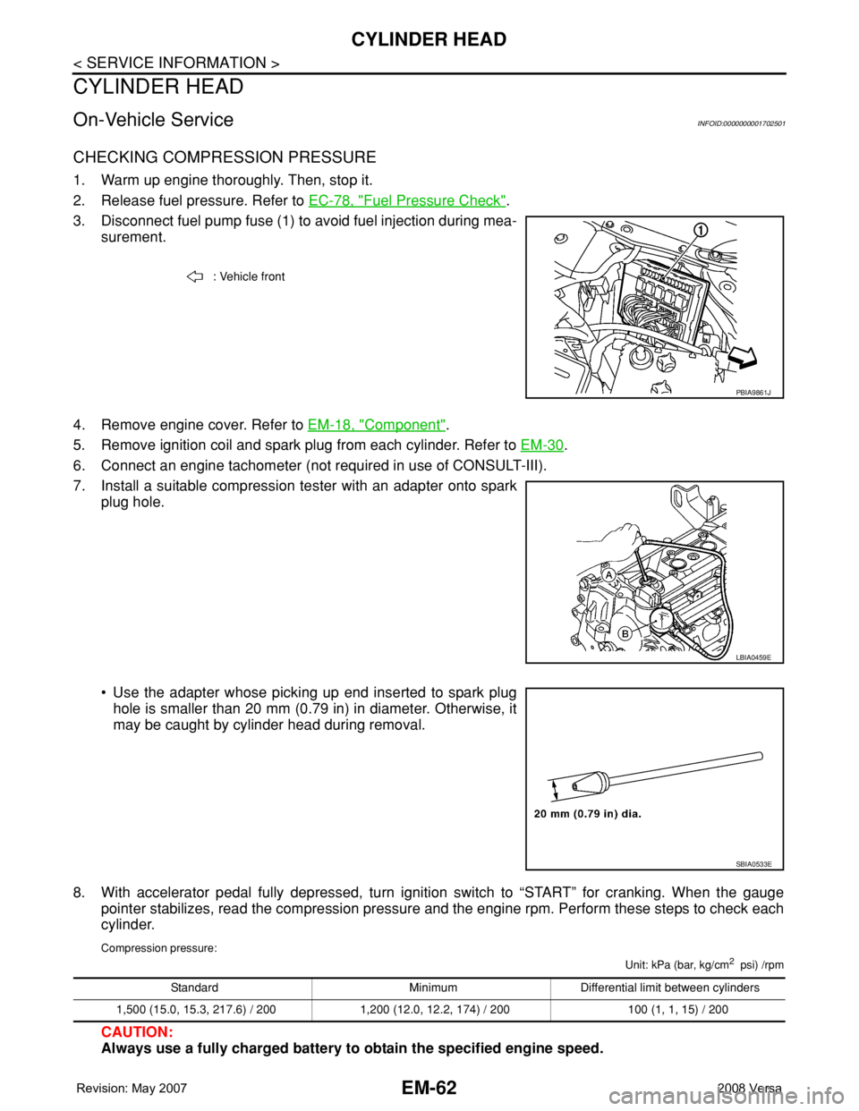
3. Disconnect fuel pump fuse (1) to avoid fuel injection during mea-
surement.
4. Remove engine cover. Refer to EM-18, "
Component".
5. Remove ignition coil and spark plug from each cylinder. Refer to EM-30
.
6. Connect an engine tachometer (not required in use of CONSULT-III).
7. Install a suitable compression tester with an adapter onto spark
plug hole.
• Use the adapter whose picking up end inserted to spark plug
hole is smaller than 20 mm (0.79 in) in diameter. Otherwise, it
may be caught by cylinder head during removal.
8. With accelerator pedal fully depressed, turn ignition switch to “START” for cranking. When the gauge
pointer stabilizes, read the compression pressure and the engine rpm. Perform these steps to check each
cylinder.
Compression pressure:
Unit: kPa (bar, kg/cm2 psi) /rpm
CAUTION:
Always use a fully charged battery to obtain the specified engine speed.
: Vehicle front
PBIA9861J
LBIA0459E
SBIA0533E
Standard Minimum Differential limit between cylinders
1,500 (15.0, 15.3, 217.6) / 200 1,200 (12.0, 12.2, 174) / 200 100 (1, 1, 15) / 200
Page 1740 of 2771
CYLINDER HEAD
EM-63
< SERVICE INFORMATION >
C
D
E
F
G
H
I
J
K
L
MA
EM
N
P O
• If the engine speed is out of the specified range, check battery liquid for proper gravity. Check engine
speed again with normal battery gravity.
• If compression pressure is below minimum value, check valve clearances and parts associated with
combustion chamber (Valve, valve seat, piston, piston ring, cylinder bore, cylinder head, cylinder head
gasket). After the checking, measure the compression pressure again.
• If some cylinder has low compression pressure, pour small amount of engine oil into the spark plug hole
of the cylinder to re-check it for compression.
- If the added engine oil improves the compression, piston rings may be worn out or damaged. Check pis-
ton rings and replace if necessary.
- If the compression pressure remains at low level despite the addition of engine oil, valves may be mal-
functioning. Check valves for damage. Replace valve or valve seat accordingly.
• If two adjacent cylinders have respectively low compression pressure and their compression remains
low even after the addition of engine oil, cylinder head gasket is leaking. In such a case, replace cylinder
head gasket.
9. After inspection is completed, install removed parts.
10. Start the engine, and confirm that the engine runs smoothly.
11. Perform trouble diagnosis. If DTC appears, erase it. Refer to EC-81
.
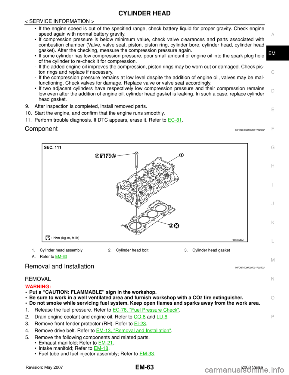
ComponentINFOID:0000000001702502
Removal and InstallationINFOID:0000000001702503
REMOVAL
WARNING:
• Put a “CAUTION: FLAMMABLE” sign in the workshop.
• Be sure to work in a well ventilated area and furnish workshop with a CO
2 fire extinguisher.
• Do not smoke while servicing fuel system. Keep open flames and sparks away from the work area.
1. Release the fuel pressure. Refer to EC-78, "
Fuel Pressure Check".
2. Drain engine coolant and engine oil. Refer to CO-8
and LU-6.
3. Remove front fender protector (RH). Refer to EI-23
.
4. Remove drive belt. Refer to EM-13, "
Removal and Installation".
5. Remove the following components and related parts.
• Exhaust manifold; Refer to EM-21
.
• Intake manifold; Refer to EM-18
.
• Fuel tube and fuel injector assembly; Refer to EM-33
.
1. Cylinder head assembly 2. Cylinder head bolt 3. Cylinder head gasket
A. Refer to EM-63
PBIC3542J
Page 1750 of 2771
ENGINE ASSEMBLY
EM-73
< SERVICE INFORMATION >
C
D
E
F
G
H
I
J
K
L
MA
EM
N
P O
• Use either 2-pole lift type or separate type lift as best you can. If board-on type is used for unavoid-
able reasons, support at the rear axle jacking point with a transmission jack or similar tool before
starting work, in preparation for the backward shift of center of gravity.
• For supporting points for lifting and jacking point at rear axle, refer to GI-38, "
Garage Jack and
Safety Stand and 2-Pole Lift".
REMOVAL
Remove the engine and the transaxle assembly from the vehicle downward. Separate the engine and the tran-
saxle.
1. Remove engine undercover
2. Drain engine coolant from radiator. Refer to CO-8, "
Changing Engine Coolant".
CAUTION:
• Perform this step when the engine is cold.
• Do not spill engine coolant on drive belt.
3. Remove front fender protector (RH and LH); Refer to EI-23
.
4. Remove exhaust front tube; Refer to EX-4
.
5. Remove drive shafts (LH and RH) from steering knuckle. Refer to FAX-8
.
6. Remove transaxle joint bolts which pierce at oil pan (upper) lower rear side. Refer to AT-226
(A/T models),
CVT-178
(CVT) or MT-16 (M/T models).
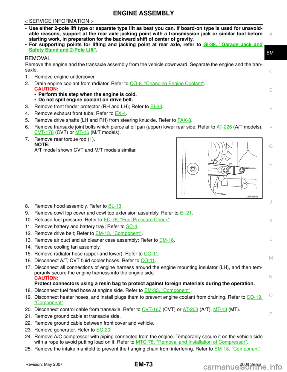
7. Remove rear torque rod (1).
NOTE:
A/T model shown CVT and M/T models similar.
8. Remove hood assembly. Refer to BL-13
.
9. Remove cowl top cover and cowl top extension assembly. Refer to EI-21
.
10. Release fuel pressure. Refer to EC-78, "
Fuel Pressure Check".
11. Remove battery and battery tray; Refer to SC-4
.
12. Remove drive belt; Refer to EM-13, "
Component".
13. Remove air duct and air cleaner case assembly; Refer to EM-16
.
14. Remove cooling fan assembly.
15. Remove radiator hose (upper and lower). Refer to CO-11
.
16. Disconnect A/T, CVT fluid cooler hoses. Refer to CO-11
.
17. Disconnect all connections of engine harness around the engine mounting insulator (LH), and then tem-
porarily secure the engine harness into the engine side.
CAUTION:
Protect connectors using a resin bag to protect against foreign materials during the operation.
18. Disconnect fuel feed hose at engine side. Refer to EM-33, "
Component".
19. Disconnect heater hoses, and install plugs them to prevent engine coolant from draining. Refer to CO-19,
"Component".
20. Disconnect control cable from transaxle. Refer to CVT-167
(CVT) or AT-203 (A/T), MT-13 (MT).
21. Remove ground cable at transaxle side.
22. Remove ground cable between front cover and vehicle.
23. Remove generator. Refer to SC-20
.
24. Remove A/C compressor with piping connected from the engine. Temporarily secure it on the vehicle side
with a rope to avoid putting load on it. Refer to MTC-78, "
Removal and Installation of Compressor".
25. Remove the intake manifold to prevent the hanging chain from interfering. Refer to EM-18, "
Component".
LBIA0460E
Page 1824 of 2771
FL-4
< SERVICE INFORMATION >
FUEL SYSTEM
FUEL SYSTEM
Checking Fuel LineINFOID:0000000001703097
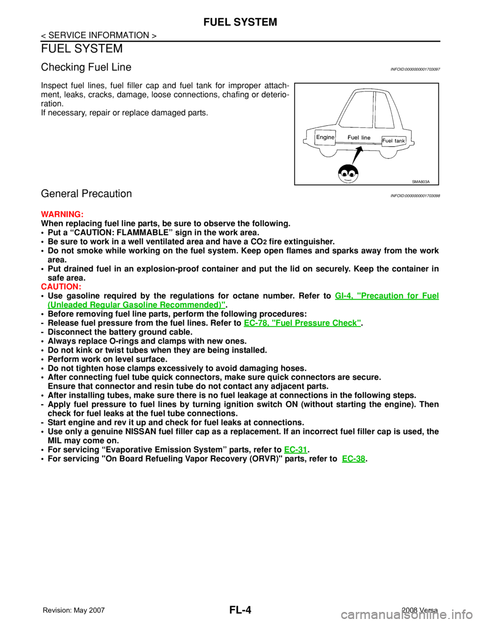
Inspect fuel lines, fuel filler cap and fuel tank for improper attach-
ment, leaks, cracks, damage, loose connections, chafing or deterio-
ration.
If necessary, repair or replace damaged parts.
General PrecautionINFOID:0000000001703098
WARNING:
When replacing fuel line parts, be sure to observe the following.
• Put a “CAUTION: FLAMMABLE” sign in the work area.
• Be sure to work in a well ventilated area and have a CO
2 fire extinguisher.
• Do not smoke while working on the fuel system. Keep open flames and sparks away from the work
area.
• Put drained fuel in an explosion-proof container and put the lid on securely. Keep the container in
safe area.
CAUTION:
• Use gasoline required by the regulations for octane number. Refer to GI-4, "
Precaution for Fuel
(Unleaded Regular Gasoline Recommended)".
• Before removing fuel line parts, perform the following procedures:
- Release fuel pressure from the fuel lines. Refer to EC-78, "
Fuel Pressure Check".
- Disconnect the battery ground cable.
• Always replace O-rings and clamps with new ones.
• Do not kink or twist tubes when they are being installed.
• Perform work on level surface.
• Do not tighten hose clamps excessively to avoid damaging hoses.
• After connecting fuel tube quick connectors, make sure quick connectors are secure.
Ensure that connector and resin tube do not contact any adjacent parts.
• After installing tubes, make sure there is no fuel leakage at connections in the following steps.
- Apply fuel pressure to fuel lines by turning ignition switch ON (without starting the engine). Then
check for fuel leaks at the fuel tube connections.
- Start engine and rev it up and check for fuel leaks at connections.
• Use only a genuine NISSAN fuel filler cap as a replacement. If an incorrect fuel filler cap is used, the
MIL may come on.
• For servicing “Evaporative Emission System” parts, refer to EC-31
.
• For servicing "On Board Refueling Vapor Recovery (ORVR)" parts, refer to EC-38
.
SMA803A
Page 1826 of 2771
FL-6
< SERVICE INFORMATION >
FUEL LEVEL SENSOR UNIT, FUEL FILTER AND FUEL PUMP ASSEMBLY
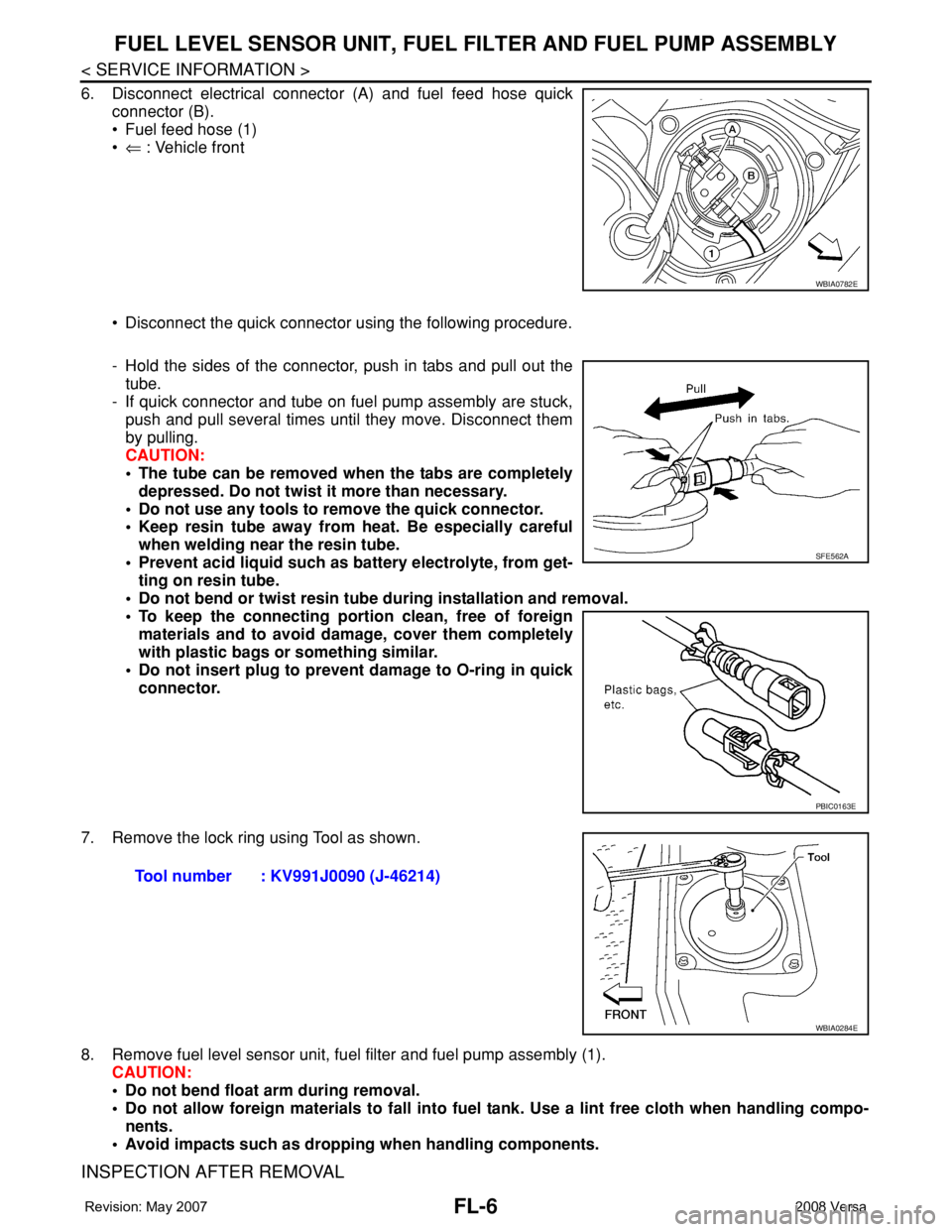
6. Disconnect electrical connector (A) and fuel feed hose quick
connector (B).
• Fuel feed hose (1)
•⇐ : Vehicle front
• Disconnect the quick connector using the following procedure.
- Hold the sides of the connector, push in tabs and pull out the
tube.
- If quick connector and tube on fuel pump assembly are stuck,
push and pull several times until they move. Disconnect them
by pulling.
CAUTION:
• The tube can be removed when the tabs are completely
depressed. Do not twist it more than necessary.
• Do not use any tools to remove the quick connector.
• Keep resin tube away from heat. Be especially careful
when welding near the resin tube.
• Prevent acid liquid such as battery electrolyte, from get-
ting on resin tube.
• Do not bend or twist resin tube during installation and removal.
• To keep the connecting portion clean, free of foreign
materials and to avoid damage, cover them completely
with plastic bags or something similar.
• Do not insert plug to prevent damage to O-ring in quick
connector.
7. Remove the lock ring using Tool as shown.
8. Remove fuel level sensor unit, fuel filter and fuel pump assembly (1).
CAUTION:
• Do not bend float arm during removal.
• Do not allow foreign materials to fall into fuel tank. Use a lint free cloth when handling compo-
nents.
• Avoid impacts such as dropping when handling components.
INSPECTION AFTER REMOVAL
WBIA0782E
SFE562A
PBIC0163E
Tool number : KV991J0090 (J-46214)
WBIA0284E
Page 1830 of 2771
FL-10
< SERVICE INFORMATION >
FUEL TANK
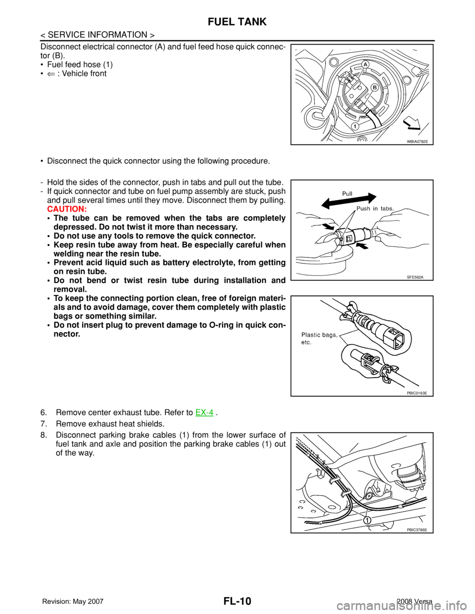
Disconnect electrical connector (A) and fuel feed hose quick connec-
tor (B).
• Fuel feed hose (1)
•⇐ : Vehicle front
• Disconnect the quick connector using the following procedure.
- Hold the sides of the connector, push in tabs and pull out the tube.
- If quick connector and tube on fuel pump assembly are stuck, push
and pull several times until they move. Disconnect them by pulling.
CAUTION:
• The tube can be removed when the tabs are completely
depressed. Do not twist it more than necessary.
• Do not use any tools to remove the quick connector.
• Keep resin tube away from heat. Be especially careful when
welding near the resin tube.
• Prevent acid liquid such as battery electrolyte, from getting
on resin tube.
• Do not bend or twist resin tube during installation and
removal.
• To keep the connecting portion clean, free of foreign materi-
als and to avoid damage, cover them completely with plastic
bags or something similar.
• Do not insert plug to prevent damage to O-ring in quick con-
nector.
6. Remove center exhaust tube. Refer to EX-4
.
7. Remove exhaust heat shields.
8. Disconnect parking brake cables (1) from the lower surface of
fuel tank and axle and position the parking brake cables (1) out
of the way.
WBIA0782E
SFE562A
PBIC0163E
PBIC3786E
Page 1831 of 2771
FUEL TANK
FL-11
< SERVICE INFORMATION >
C
D
E
F
G
H
I
J
K
L
MA
FL
N
P O
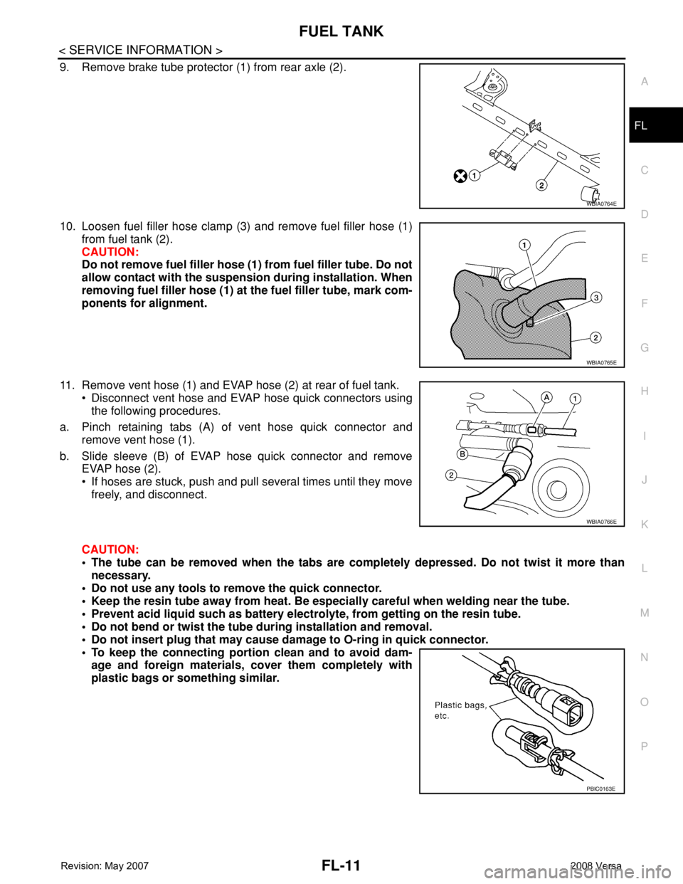
9. Remove brake tube protector (1) from rear axle (2).
10. Loosen fuel filler hose clamp (3) and remove fuel filler hose (1)
from fuel tank (2).
CAUTION:
Do not remove fuel filler hose (1) from fuel filler tube. Do not
allow contact with the suspension during installation. When
removing fuel filler hose (1) at the fuel filler tube, mark com-
ponents for alignment.
11. Remove vent hose (1) and EVAP hose (2) at rear of fuel tank.
• Disconnect vent hose and EVAP hose quick connectors using
the following procedures.
a. Pinch retaining tabs (A) of vent hose quick connector and
remove vent hose (1).
b. Slide sleeve (B) of EVAP hose quick connector and remove
EVAP hose (2).
• If hoses are stuck, push and pull several times until they move
freely, and disconnect.
CAUTION:
• The tube can be removed when the tabs are completely depressed. Do not twist it more than
necessary.
• Do not use any tools to remove the quick connector.
• Keep the resin tube away from heat. Be especially careful when welding near the tube.
• Prevent acid liquid such as battery electrolyte, from getting on the resin tube.
• Do not bend or twist the tube during installation and removal.
• Do not insert plug that may cause damage to O-ring in quick connector.
• To keep the connecting portion clean and to avoid dam-
age and foreign materials, cover them completely with
plastic bags or something similar.
WBIA0764E
WBIA0765E
WBIA0766E
PBIC0163E
Page 1852 of 2771
GI-1
GENERAL INFORMATION
C
D
E
F
G
H
I
J
K
L
MB
GI
SECTION GI
N
O
P
CONTENTS
GENERAL INFORMATION
SERVICE INFORMATION ............................2
PRECAUTIONS ...................................................2
Description ................................................................2
Precaution for Supplemental Restraint System
(SRS) "AIR BAG" and "SEAT BELT PRE-TEN-
SIONER" ...................................................................
2
Precaution Necessary for Steering Wheel Rota-
tion After Battery Disconnect .....................................
2
General Precaution ...................................................3
Precaution for Three Way Catalyst ...........................4
Precaution for Fuel (Unleaded Regular Gasoline
Recommended) .........................................................
4
Precaution for Multiport Fuel Injection System or
Engine Control System .............................................
5
Precaution for Hoses .................................................5
Precaution for Engine Oils ........................................6
Precaution for Air Conditioning .................................6
HOW TO USE THIS MANUAL ............................7
Description ................................................................7
Terms ........................................................................7
Units ..........................................................................7
Contents ....................................................................7
Relation between Illustrations and Descriptions .......8
Component ................................................................8
How to Follow Trouble Diagnosis ..............................9
How to Read Wiring Diagram ..................................13
Abbreviations ..........................................................20
SERVICE INFORMATION FOR ELECTRICAL
INCIDENT ...........................................................
22
How to Check Terminal ...........................................22
How to Perform Efficient Diagnosis for an Electri-
cal Incident ..............................................................
25
Control Units and Electrical Parts ............................32
CONSULT-III CHECKING SYSTEM .................35
Description ...............................................................35
Function and System Application ............................35
CONSULT-III Data Link Connector (DLC) Circuit ....36
LIFTING POINT .................................................38
Special Service Tool ................................................38
Garage Jack and Safety Stand and 2-Pole Lift .......38
Board-On Lift ...........................................................39
TOW TRUCK TOWING .....................................40
Tow Truck Towing ...................................................40
Vehicle Recovery (Freeing a Stuck Vehicle) ...........40
TIGHTENING TORQUE OF STANDARD
BOLTS ...............................................................
41
Tightening Torque Table .........................................41
RECOMMENDED CHEMICAL PRODUCTS
AND SEALANTS ...............................................
42
Recommended Chemical Product and Sealant .......42
IDENTIFICATION INFORMATION ....................43
Model Variation ........................................................43
Dimensions ..............................................................46
Wheels & Tires ........................................................46
TERMINOLOGY ................................................47
SAE J1930 Terminology List ...................................47