Page 1612 of 2771

EC-538
< SERVICE INFORMATION >
IGNITION SIGNAL
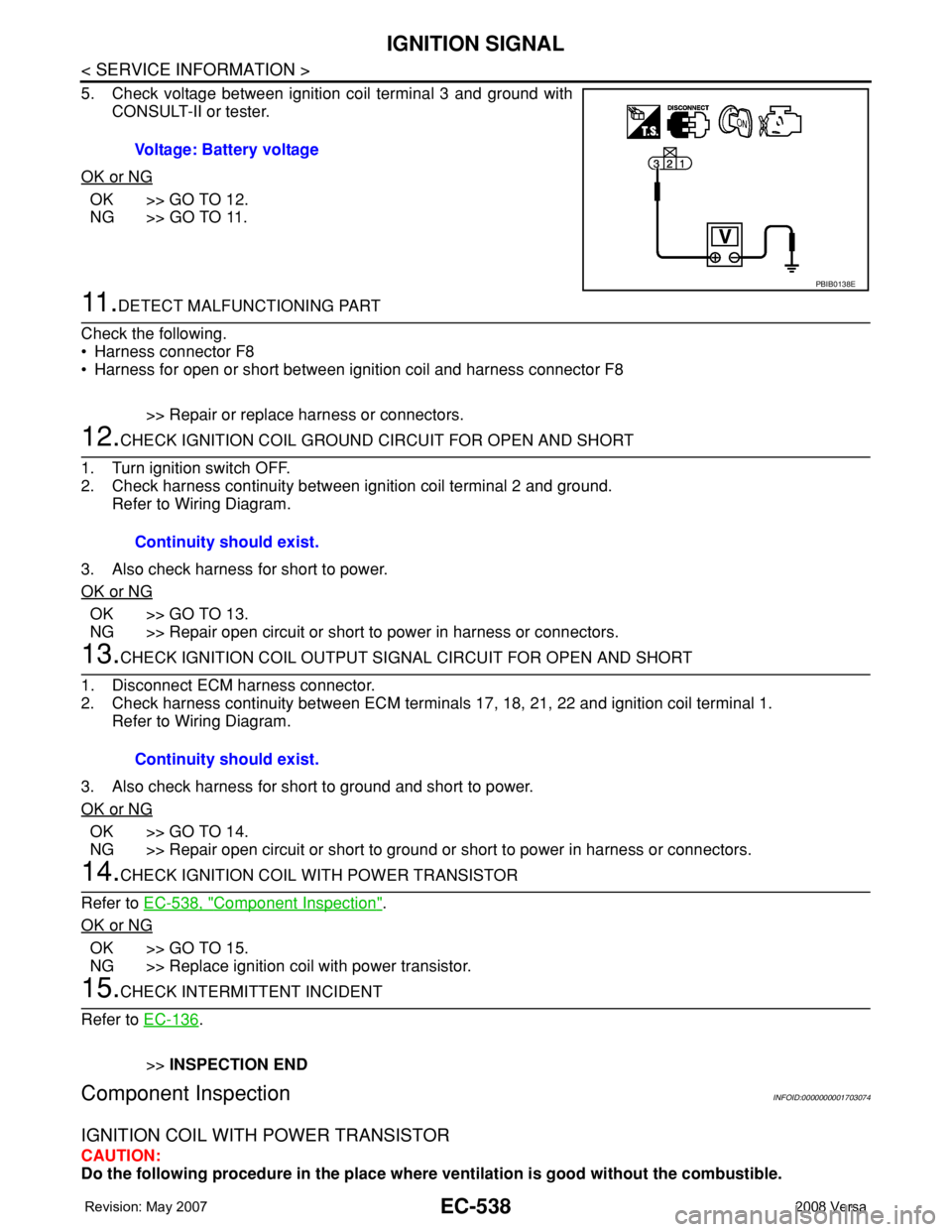
5. Check voltage between ignition coil terminal 3 and ground with
CONSULT-II or tester.
OK or NG
OK >> GO TO 12.
NG >> GO TO 11.
11 .DETECT MALFUNCTIONING PART
Check the following.
• Harness connector F8
• Harness for open or short between ignition coil and harness connector F8
>> Repair or replace harness or connectors.
12.CHECK IGNITION COIL GROUND CIRCUIT FOR OPEN AND SHORT
1. Turn ignition switch OFF.
2. Check harness continuity between ignition coil terminal 2 and ground.
Refer to Wiring Diagram.
3. Also check harness for short to power.
OK or NG
OK >> GO TO 13.
NG >> Repair open circuit or short to power in harness or connectors.
13.CHECK IGNITION COIL OUTPUT SIGNAL CIRCUIT FOR OPEN AND SHORT
1. Disconnect ECM harness connector.
2. Check harness continuity between ECM terminals 17, 18, 21, 22 and ignition coil terminal 1.
Refer to Wiring Diagram.
3. Also check harness for short to ground and short to power.
OK or NG
OK >> GO TO 14.
NG >> Repair open circuit or short to ground or short to power in harness or connectors.
14.CHECK IGNITION COIL WITH POWER TRANSISTOR
Refer to EC-538, "
Component Inspection".
OK or NG
OK >> GO TO 15.
NG >> Replace ignition coil with power transistor.
15.CHECK INTERMITTENT INCIDENT
Refer to EC-136
.
>>INSPECTION END
Component InspectionINFOID:0000000001703074
IGNITION COIL WITH POWER TRANSISTOR
CAUTION:
Do the following procedure in the place where ventilation is good without the combustible. Voltage: Battery voltage
PBIB0138E
Continuity should exist.
Continuity should exist.
Page 1622 of 2771

EC-548
< SERVICE INFORMATION >
SERVICE DATA AND SPECIFICATIONS (SDS)
SERVICE DATA AND SPECIFICATIONS (SDS)
Fuel PressureINFOID:0000000001703081
Idle Speed and Ignition TimingINFOID:0000000001703082
*: Under the following conditions:
• Air conditioner switch: OFF
• Electric load: OFF (Lights, heater fan & rear window defogger)
• Steering wheel: Kept in straight-ahead position
Calculated Load ValueINFOID:0000000001703083
Mass Air Flow SensorINFOID:0000000001703084
*: Engine is warmed up to normal operating temperature and running under no load.
Intake Air Temperature SensorINFOID:0000000001703085
Engine Coolant Temperature SensorINFOID:0000000001703086
Fuel pressure at idle
Approximately 350 kPa (3.57 kg/cm2, 51 psi)
Target idle speedA/T No load* (in P or N position)
700 ± 50 rpm CVT No load* (In P or N position)
M/T No load* (in Neutral position)
Air conditioner: ONA/T In P or N position
850 rpm or more CVT In P or N position
M/T In Neutral position
Ignition timingA/T In P or N position
13 ± 5° BTDC CVT In P or N position
M/T In Neutral position
Calculated load value% (Using CONSULT-II or GST)
At idle10 - 35
At 2,500 rpm10 - 35
Supply voltageBattery voltage (11 - 14V)
Output voltage at idle1.0 - 1.3*V
Mass air flow (Using CONSULT-II or GST)1.0 - 4.0 g·m/sec at idle*
2.0 - 10.0 g·m/sec at 2,500 rpm*
Temperature °C (°F) Resistance kΩ
25 (77)1.800 - 2.200
Temperature °C (°F) Resistance kΩ
20 (68)2.1 - 2.9
50 (122)0.68 - 1.00
90 (194)0.236 - 0.260
Page 1653 of 2771
EI-30
< ON-VEHICLE REPAIR >
TRUNK LID FINISHER
TRUNK LID FINISHER
Removal and InstallationINFOID:0000000001704231
REMOVAL
1. Disconnect the negative and positive battery cables.
2. Open trunk lid, remove trunk lid finisher inner. Refer to EI-53
.
3. Remove trunk lid finisher outer nuts.
4. Release the clips, then pull trunk lid finisher outer away from trunk lid.
5. Disconnect trunk lid opener switch connector and trunk opener request switch connector, then remove
trunk lid finisher outer.
INSTALLATION
Installation is in the reverse order of removal.
1. Trunk lid finisher outer 2. Trunk lid opener switch connector 3. Trunk opener request switch connector
A. Clip C101
WIIA1413E
Page 1654 of 2771

REAR AIR SPOILER
EI-31
< ON-VEHICLE REPAIR >
C
D
E
F
G
H
J
K
L
MA
B
EI
N
O
P
REAR AIR SPOILER
Removal and InstallationINFOID:0000000001704232
Removal
1. Disconnect the negative and positive battery cables.
2. Remove back door finisher upper. Refer to EI-36
.
3. Disconnect high mounted stop lamp connector.
4. Remove the nuts and carefully lift the rear air spoiler from the back door.
CAUTION:
Use care not to damage painted surfaces during removal of, or releasing adhesive backed foam
tapes if equipped.
5. Release the high mounted stop lamp harness grommet from back door, then remove rear air spoiler.
Installation
Installation is in the reverse order of removal.
NOTE:
• Before installing rear air spoiler, clean the surface where it will be mounted with isopropyl alcohol or equiva-
lent to degrease the surface.
• Before installing, be sure there are no gaps or waves in the foam tape (if equipped) where the surfaces
meet.
• During installation, be sure grommet of high mounted stop lamp harness is fully seated into back door open-
ing prior to final rear air spoiler placement.
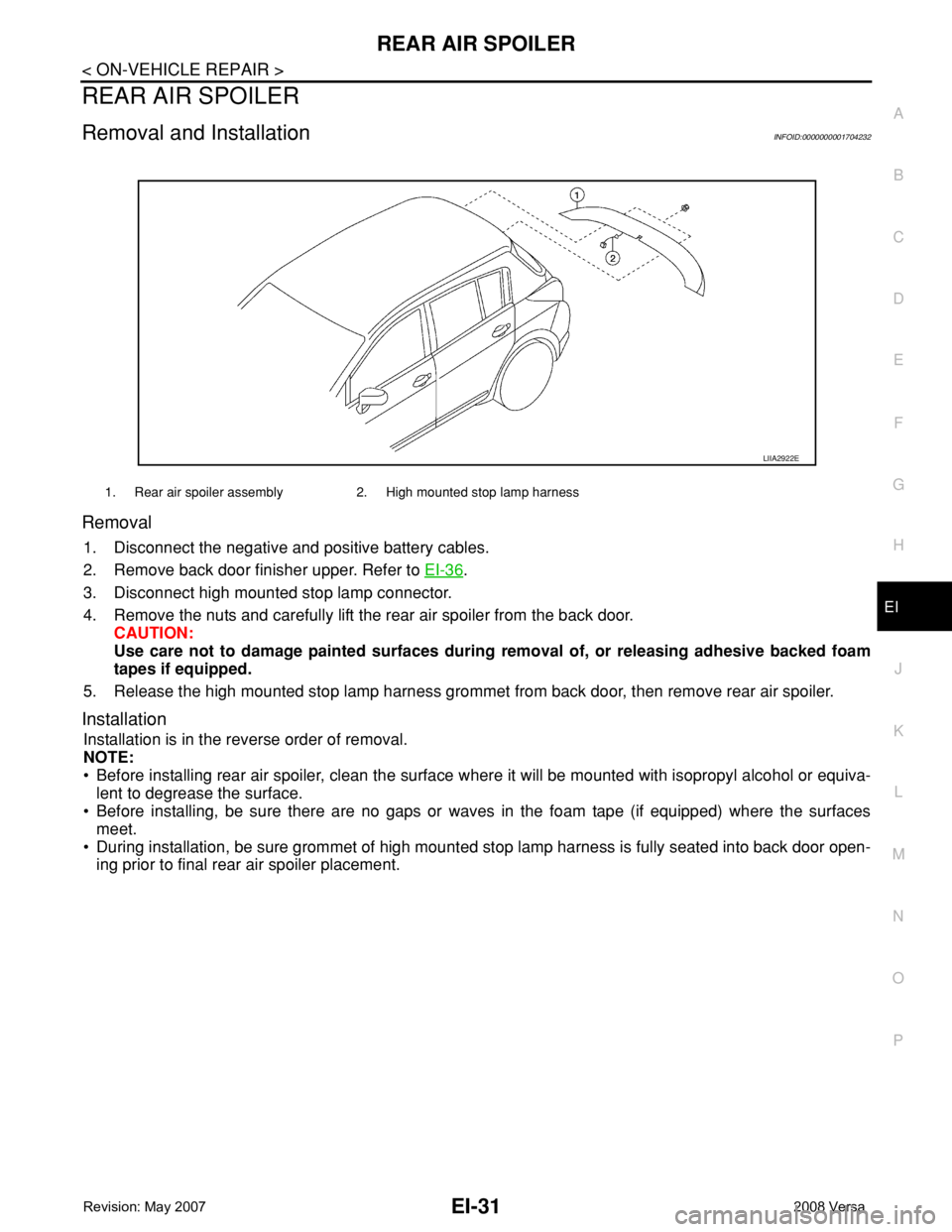
1. Rear air spoiler assembly 2. High mounted stop lamp harness
LIIA2922E
Page 1655 of 2771
EI-32
< ON-VEHICLE REPAIR >
DOOR FINISHER
DOOR FINISHER
Removal and InstallationINFOID:0000000001704233
FRONT DOOR
Removal
1. Open front door and front door window.
2. Disconnect the negative and positive battery cables.
3. Release the front door inside handle escutcheon pawls, then
slide the escutcheon rearward to remove from front door fin-
isher.
1. Power window and door lock/unlock
switch finisher2. Front door finisher 3. Inside handle escutcheon
Clip C101
LIIA2572E
PIIB6040E
Page 1657 of 2771
EI-34
< ON-VEHICLE REPAIR >
DOOR FINISHER
Removal
1. Open rear door and rear door window.
2. Disconnect the negative and positive battery cables.
3. Release the rear door inside handle escutcheon pawls, then
slide the escutcheon rearward to remove from rear door finisher.
4. Insert a trim stick (A), or suitable tool into back edge of rear door
power window switch finisher. Lift upward to release the clips
and remove.
5. Disconnect rear door power window switch harness connector.
6. Remove rear door finisher screw.
1. Rear power window switch finisher 2. Rear door finisher 3. Inside handle escutcheon
Clip C101
LIIA2573E
PIIB6040E
WIIA1238E
Page 1666 of 2771
FLOOR TRIM
EI-43
< ON-VEHICLE REPAIR >
C
D
E
F
G
H
J
K
L
MA
B
EI
N
O
P
FLOOR TRIM
Removal and InstallationINFOID:0000000001704238
REMOVAL
1. Disconnect both the negative and positive battery cables, then wait at least 3 minutes.
2. Remove front seat assembly RH/LH and rear seat cushion. Refer to SE-11, "
Removal and Installation"
and SE-15, "Removal and Installation".
3. Remove center console and floor bracket. Refer to IP-11, "
Removal and Installation".
4. Remove instrument lower cover. Refer to IP-11, "
Removal and Installation".
5. Remove front kicking plate inner RH/LH, center pillar lower garnish RH/LH, and rear kicking plate inner
RH/LH. Refer to EI-38, "
Removal and Installation".
1. Clip C101 2. Steering column shaft cover 3. Floor carpet hook
4. Front floor spacer 5. Rear floor spacer 6. Floor trim
Metal clip Clip CF110⇐Vehicle front
LIIA2575E
Page 1670 of 2771

HEADLINING
EI-47
< ON-VEHICLE REPAIR >
C
D
E
F
G
H
J
K
L
MA
B
EI
N
O
P
Removal and Installation - HatchbackINFOID:0000000001704240
REMOVAL
1. Remove the negative and positive battery cables.
2. Remove front seat assembly RH/LH. Refer to SE-11, "
Removal and Installation".
3. Remove rear seat cushion and rear seatback. Refer to SE-15, "
Removal and Installation".
4. Remove front seat belt shoulder anchor RH/LH. Refer to SB-3, "
Removal and Installation of Front Seat
Belt".
5. Remove center console body assembly. Refer to IP-10
.
6. Remove front pillar garnish RH/LH. Refer to EI-38, "
Removal and Installation".
7. Remove antenna feeder cable clip, then disconnect antenna
feeder cable connector.
8. Remove front and rear kicking plate inner RH/LH, center pillar lower garnish, center pillar upper garnish,
front and rear body side welt RH/LH. Refer to EI-38, "
Removal and Installation".
WARNING:
Do not reuse center pillar upper garnish if removed.
9. Remove back door weatherstrip. Refer to EI-36
.
10. Release the clips using a suitable tool, then remove the front
and rear assist grips.
11. Remove the sunvisor caps and screws, then remove sunvisor RH/LH.
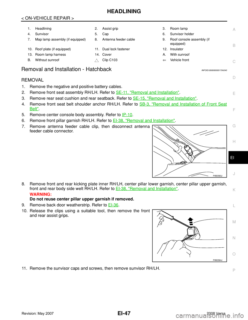
1. Headlining 2. Assist grip 3. Room lamp
4. Sunvisor 5. Cap 6. Sunvisor holder
7. Map lamp assembly (if equipped) 8. Antenna feeder cable 9. Roof console assembly (if
equipped)
10. Roof plate (if equipped) 11. Dual lock fastener 12. Insulator
13. Room lamp harness 14. Cover A. With sunroof
B. Without sunroof Clip C103⇐Vehicle front
PIIB2583J
PIIB2584J