2008 NISSAN LATIO wheel
[x] Cancel search: wheelPage 510 of 2771
BL-76
< SERVICE INFORMATION >
INTELLIGENT KEY SYSTEM
System Description
INFOID:0000000001703999
• The Intelligent Key system is a system that makes it possible to lock and unlock the door locks (door lock/
unlock function), and start the engine (engine start function) by carrying around the Intelligent Key (without
some key operation), which operates based on the results of electronic ID verification using two-way com-
munications between the Intelligent Key and the vehicle (Intelligent Key unit).
• Vehicles equipped with a manual transmission include a key interlock solenoid located in the steering col-
umn to prevent accidental shut-off of the ignition switch and locking of the steering wheel during driving con-
dition when the vehicle is moving.
CAUTION:
The driver should always carry the Intelligent Key
• Operation of the remote controller buttons on the Intelligent Key also provides the same functions as the
remote control entry system. (Remote keyless entry functions)
• If an action that does not meet the operating conditions of the Intelligent Key system is taken, the buzzer
goes off to inform the driver. (Warning chime functions)
• When a door lock is locked or unlocked with request switch or remote controller button operation, the hazard
lamps flash and the buzzer (outside vehicle) sounds (Hazard and buzzer reminder function).
• Even if the Intelligent Key battery is completely discharged, the door locks can be locked and unlocked and
the engine started with the mechanical key built into the Intelligent Key.
• The settings for each function can be changed with the CONSULT-III.
• If an Intelligent Key is lost, a new Intelligent Key can be registered. A maximum of 4 Intelligent Keys can be
registered.
• It has been made possible to diagnose the system and register an Intelligent Key with the CONSULT-III.
DOOR LOCK/UNLOCK FUNCTION
Only when pressing the request switch, it is possible to lock and unlock the door by carrying around the Intelli-
gent Key (without some key operation).
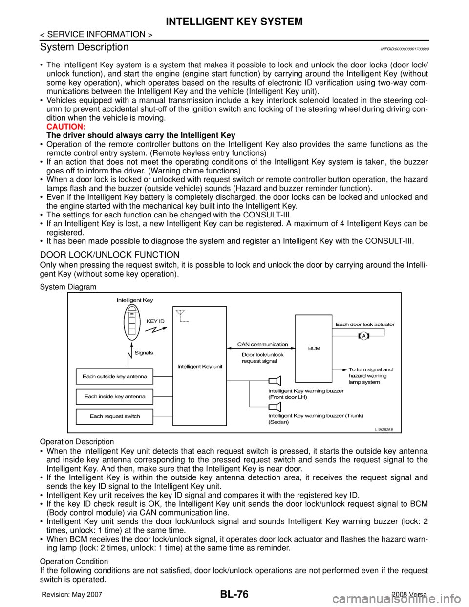
System Diagram
Operation Description
• When the Intelligent Key unit detects that each request switch is pressed, it starts the outside key antenna
and inside key antenna corresponding to the pressed request switch and sends the request signal to the
Intelligent Key. And then, make sure that the Intelligent Key is near door.
• If the Intelligent Key is within the outside key antenna detection area, it receives the request signal and
sends the key ID signal to the Intelligent Key unit.
• Intelligent Key unit receives the key ID signal and compares it with the registered key ID.
• If the key ID check result is OK, the Intelligent Key unit sends the door lock/unlock request signal to BCM
(Body control module) via CAN communication line.
• Intelligent Key unit sends the door lock/unlock signal and sounds Intelligent Key warning buzzer (lock: 2
times, unlock: 1 time) at the same time.
• When BCM receives the door lock/unlock signal, it operates door lock actuator and flashes the hazard warn-
ing lamp (lock: 2 times, unlock: 1 time) at the same time as reminder.
Operation Condition
If the following conditions are not satisfied, door lock/unlock operations are not performed even if the request
switch is operated.
LIIA2926E
Page 664 of 2771

BL-230
< SERVICE INFORMATION >
BODY REPAIR
6. 1st roof rail assembly
7. Front roof rail assembly
8. Sun roof assembly
9. Front roof rail assembly (if equipped with sunroof)
10. Roof side rail reinforcement (RH & LH)
11. Inner center pillar (RH & LH)
12. Hood assembly
13. Center pillar reinforcement (RH & LH)
14. Front pillar inner (RH & LH)
15. Front pillar upper reinforcement (RH & LH)
16. Front pillar lower reinforcement (RH & LH)
17. Fender (RH & LH)
18. Side body (RH & LH)
19. Side body assembly (RH & LH)
20. Outer sill (RH & LH)
21. Outer sill reinforcement (RH & LH)
22. Front door assembly (RH & LH)
23. Outer front door panel (RH & LH)
24. Outer rear door panel (RH & LH)
25. Rear door assembly (RH & LH)
26. Rear fender (RH & LH)
27. Rear fender assembly (RH & LH)
28. Rear fender corner (RH & LH)
29. Rear fender extension (RH & LH)
30. Rear combination lamp base (RH & LH)
31. Rear pillar inner reinforcement (RH & LH)
32. Rear wheel housing outer (RH & LH)
33. Rear wheel housing inner (RH & LH)
34. Rear spring base assembly (RH & LH)
35. Rear seatback hinge bracket (RH & LH)
36. Rear seatback catch bracket (RH & LH)
37. Rear pillar inner (RH & LH)
38. Rear roof rail reinforcement (RH & LH)
39. Rear roof rail brace (RH & LH)
40. Rear panel
41. Rear bumper fascia lower bracket
42. Rear bumper fascia upper bracket
43. Rear bumper fascia center bracket
44. Rear panel assembly
45. Back door assembly
Page 666 of 2771

BL-232
< SERVICE INFORMATION >
BODY REPAIR
7. Front roof rail assembly
8. Sun roof assembly
9. Front roof rail assembly (if equipped with sunroof)
10. Roof side rail reinforcement (RH & LH)
11. Inner center pillar (RH & LH)
12. Hood assembly
13. Center pillar reinforcement (RH & LH)
14. Front pillar inner (RH & LH)
15. Front pillar upper reinforcement (RH & LH)
16. Front pillar lower reinforcement (RH & LH)
17. Fender (RH & LH)
18. Side body (RH & LH)
19. Side body assembly (RH & LH)
20. Outer sill (RH & LH)
21. Outer sill reinforcement (RH & LH)
22. Front door assembly (RH & LH)
23. Outer front door panel (RH & LH)
24. Outer rear door panel (RH & LH)
25. Rear door assembly (RH & LH)
26. Rear fender (RH & LH)
27. Rear fender corner (RH & LH)
28. Rear combination lamp base (RH & LH)
29. Rear wheel housing front extension (RH & LH)
30. Rear wheel housing outer (RH & LH)
31. Rear pillar inner reinforcement (RH & LH)
32. Rear body side inner (RH & LH)
33. Rear wheel housing inner (RH & LH)
34. Rear panel assembly
35. Rear bumper fascia upper bracket
36. Rear bumper fascia center bracket
37. Trunk lid assembly
38. Parcel shelf side (RH & LH)
39. Parcel shelf assembly
40. Rear waist panel
41. Rear bumper fascia lower bracket
Corrosion ProtectionINFOID:0000000001704120
DESCRIPTION
To provide improved corrosion prevention, the following anti-corrosive measures have been implemented in
NISSAN production plants. When repairing or replacing body panels, it is necessary to use the same anti-cor-
rosive measures.
ANTI-CORROSIVE PRECOATED STEEL (GALVANNEALED STEEL)
Page 669 of 2771
BODY REPAIR
BL-235
< SERVICE INFORMATION >
C
D
E
F
G
H
J
K
L
MA
B
BL
N
O
P
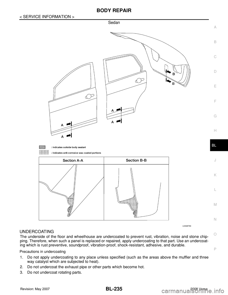
Sedan
UNDERCOATING
The underside of the floor and wheelhouse are undercoated to prevent rust, vibration, noise and stone chip-
ping. Therefore, when such a panel is replaced or repaired, apply undercoating to that part. Use an undercoat-
ing which is rust preventive, soundproof, vibration-proof, shock-resistant, adhesive, and durable.
Precautions in undercoating
1. Do not apply undercoating to any place unless specified (such as the areas above the muffler and three
way catalyst which are subjected to heat).
2. Do not undercoat the exhaust pipe or other parts which become hot.
3. Do not undercoat rotating parts.
LIIA2875E
Page 701 of 2771
BODY REPAIR
BL-267
< SERVICE INFORMATION >
C
D
E
F
G
H
J
K
L
MA
B
BL
N
O
P
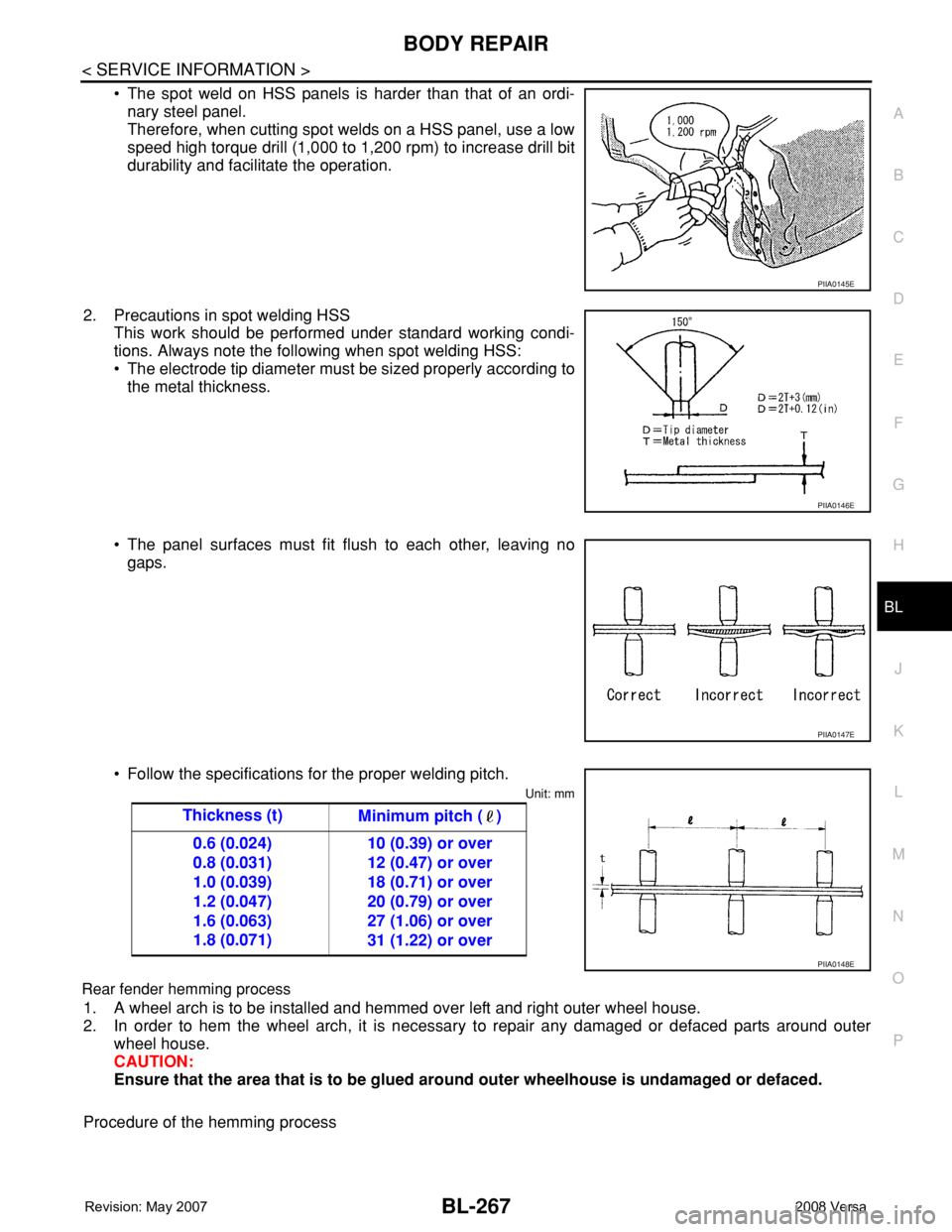
• The spot weld on HSS panels is harder than that of an ordi-
nary steel panel.
Therefore, when cutting spot welds on a HSS panel, use a low
speed high torque drill (1,000 to 1,200 rpm) to increase drill bit
durability and facilitate the operation.
2. Precautions in spot welding HSS
This work should be performed under standard working condi-
tions. Always note the following when spot welding HSS:
• The electrode tip diameter must be sized properly according to
the metal thickness.
• The panel surfaces must fit flush to each other, leaving no
gaps.
• Follow the specifications for the proper welding pitch.
Unit: mm
Rear fender hemming process
1. A wheel arch is to be installed and hemmed over left and right outer wheel house.
2. In order to hem the wheel arch, it is necessary to repair any damaged or defaced parts around outer
wheel house.
CAUTION:
Ensure that the area that is to be glued around outer wheelhouse is undamaged or defaced.
Procedure of the hemming process
PIIA0145E
PIIA0146E
PIIA0147E
Thickness (t)
Minimum pitch ( )
0.6 (0.024)
0.8 (0.031)
1.0 (0.039)
1.2 (0.047)
1.6 (0.063)
1.8 (0.071)10 (0.39) or over
12 (0.47) or over
18 (0.71) or over
20 (0.79) or over
27 (1.06) or over
31 (1.22) or over
PIIA0148E
Page 702 of 2771
BL-268
< SERVICE INFORMATION >
BODY REPAIR
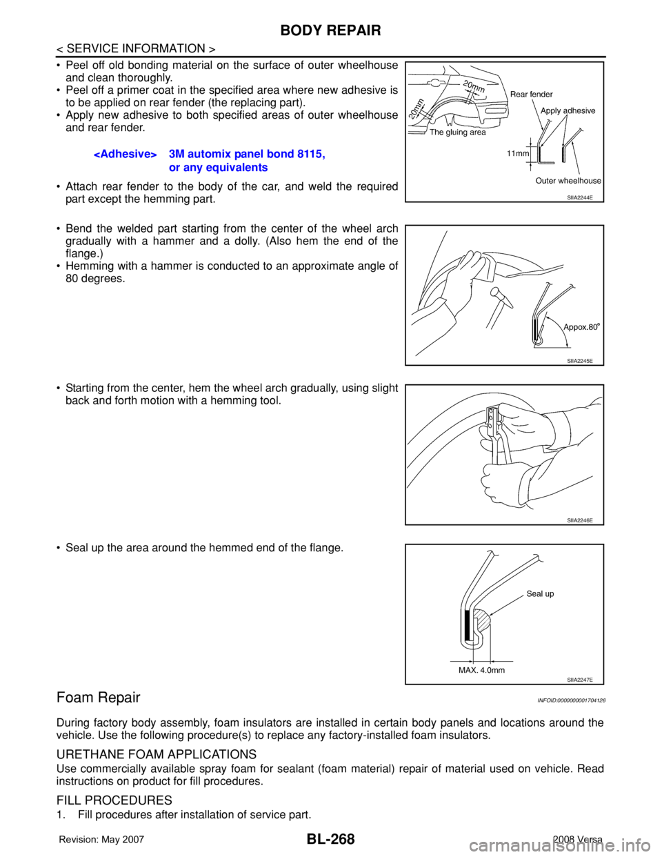
• Peel off old bonding material on the surface of outer wheelhouse
and clean thoroughly.
• Peel off a primer coat in the specified area where new adhesive is
to be applied on rear fender (the replacing part).
• Apply new adhesive to both specified areas of outer wheelhouse
and rear fender.
• Attach rear fender to the body of the car, and weld the required
part except the hemming part.
• Bend the welded part starting from the center of the wheel arch
gradually with a hammer and a dolly. (Also hem the end of the
flange.)
• Hemming with a hammer is conducted to an approximate angle of
80 degrees.
• Starting from the center, hem the wheel arch gradually, using slight
back and forth motion with a hemming tool.
• Seal up the area around the hemmed end of the flange.
Foam RepairINFOID:0000000001704126
During factory body assembly, foam insulators are installed in certain body panels and locations around the
vehicle. Use the following procedure(s) to replace any factory-installed foam insulators.
URETHANE FOAM APPLICATIONS
Use commercially available spray foam for sealant (foam material) repair of material used on vehicle. Read
instructions on product for fill procedures.
FILL PROCEDURES
1. Fill procedures after installation of service part.
or any equivalents
SIIA2244E
SIIA2245E
SIIA2246E
SIIA2247E
Page 703 of 2771
BODY REPAIR
BL-269
< SERVICE INFORMATION >
C
D
E
F
G
H
J
K
L
MA
B
BL
N
O
P
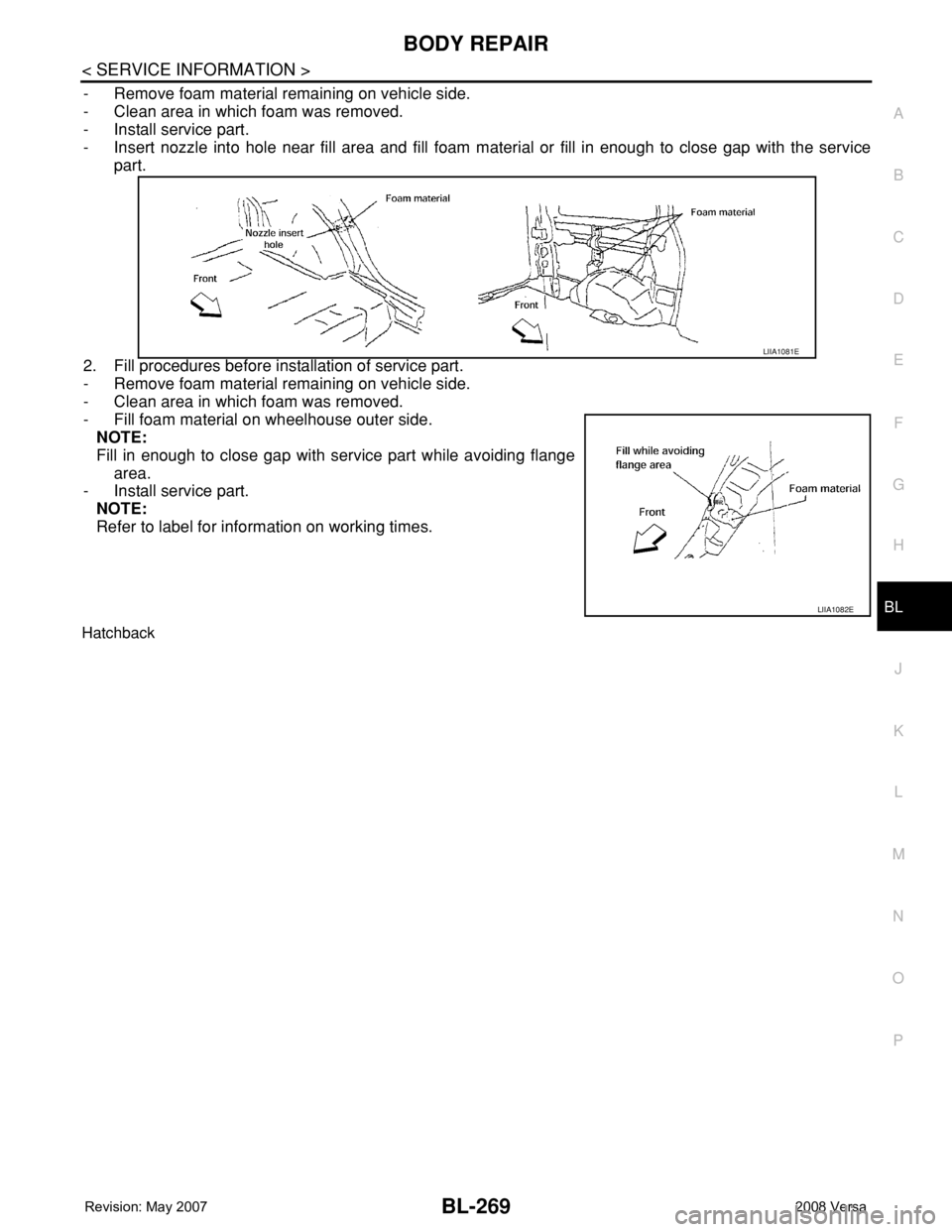
- Remove foam material remaining on vehicle side.
- Clean area in which foam was removed.
- Install service part.
- Insert nozzle into hole near fill area and fill foam material or fill in enough to close gap with the service
part.
2. Fill procedures before installation of service part.
- Remove foam material remaining on vehicle side.
- Clean area in which foam was removed.
- Fill foam material on wheelhouse outer side.
NOTE:
Fill in enough to close gap with service part while avoiding flange
area.
- Install service part.
NOTE:
Refer to label for information on working times.
Hatchback
LIIA1081E
LIIA1082E
Page 732 of 2771

BR-1
BRAKES
C
D
E
G
H
I
J
K
L
M
SECTION BR
A
B
BR
N
O
P
CONTENTS
BRAKE SYSTEM
SERVICE INFORMATION ............................2
PRECAUTIONS ...................................................2
Precaution for Supplemental Restraint System
(SRS) "AIR BAG" and "SEAT BELT PRE-TEN-
SIONER" ...................................................................
2
Precaution for Brake System ....................................2
PREPARATION ...................................................3
Commercial Service Tool ..........................................3
NOISE, VIBRATION AND HARSHNESS
(NVH) TROUBLESHOOTING .............................
4
NVH Troubleshooting Chart ......................................4
BRAKE PEDAL ...................................................5
Inspection and Adjustment ........................................5
Removal and Installation ...........................................6
BRAKE FLUID .....................................................8
On Board Inspection .................................................8
Drain and Refill ..........................................................8
Bleeding Brake System .............................................8
BRAKE TUBE AND HOSE ................................10
Hydraulic Circuit ......................................................10
Front Brake Tube and Hose ....................................10
Rear Brake Tube and Hose ....................................11
Inspection After Installation .....................................11
BRAKE MASTER CYLINDER ............................13
On-Board Inspection ...............................................13
Removal and Installation .........................................13
Disassembly and Assembly ....................................13
BRAKE BOOSTER ...........................................18
On Board Inspection ................................................18
Removal and Installation .........................................18
VACUUM LINES ...............................................21
Component ..............................................................21
Removal and Installation .........................................21
Inspection ................................................................21
FRONT DISC BRAKE .......................................23
On Board Inspection ................................................23
Component ..............................................................23
Removal and Installation of Brake Pad ...................24
Removal and Installation of Brake Caliper Assem-
bly ............................................................................
25
Disassembly and Assembly of Brake Caliper As-
sembly .....................................................................
25
Brake Burnishing Procedure ....................................28
REAR DRUM BRAKE .......................................29
Component ..............................................................29
Removal and Installation of Drum Brake Assembly
....
29
Removal and Installation of Wheel Cylinder ............32
Disassembly and Assembly of Wheel Cylinder .......32
SERVICE DATA AND SPECIFICATIONS
(SDS) .................................................................
33
General Specification ..............................................33
Brake Pedal .............................................................33
Check Valve ............................................................33
Brake Booster ..........................................................33
Front Disc Brake ......................................................33
Rear Drum Brake .....................................................34