2008 NISSAN LATIO wheel
[x] Cancel search: wheelPage 805 of 2771

CL-4
< SERVICE INFORMATION >
NOISE, VIBRATION AND HARSHNESS (NVH) TROUBLESHOOTING
NOISE, VIBRATION AND HARSHNESS (NVH) TROUBLESHOOTING
NVH Troubleshooting ChartINFOID:0000000001703116
Use the chart below to help you find the cause of the symptom. The numbers indicate the order of the inspec-
tion. If necessary, repair or replace these parts.
Reference pageCL-5CL-8EM-72CL-11CL-13EM-93
SUSPECTED PARTS (Possible cause)
CLUTCH PEDAL (Inspection and adjustment)
CLUTCH LINE (Air in line)
ENGINE MOUNTING (Loose)
CSC (Concentric slave cylinder) (Worn, dirty or damaged)
CLUTCH DISC (Out of true)
CLUTCH DISC (Runout is excessive)
CLUTCH DISC (Lining broken)
CLUTCH DISC (Dirty or burned)
CLUTCH DISC (Oily)
CLUTCH DISC (Worn out)
CLUTCH DISC (Hardened)
CLUTCH DISC (Lack of spline grease)
DIAPHRAGM SPRING (Damaged)
DIAPHRAGM SPRING (Out of tip alignment)
PRESSURE PLATE (Distortion)
FLYWHEEL (Distortion)
SymptomClutch grabs/chatters 1 2 2 2 2 2
Clutch pedal spongy 1
Clutch noisy 1
Clutch slips 1 2 2 3 4 5
Clutch does not disengage 12 55555 5667
Page 814 of 2771
CLUTCH DISC, CLUTCH COVER AND FLYWHEEL
CL-13
< SERVICE INFORMATION >
D
E
F
G
H
I
J
K
L
MA
B
CL
N
O
P
CLUTCH DISC, CLUTCH COVER AND FLYWHEEL
Removal and InstallationINFOID:0000000001703123
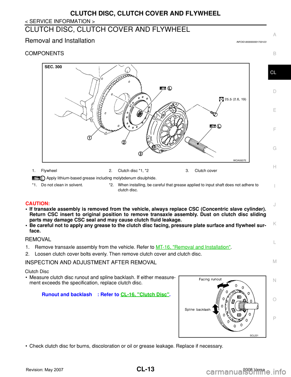
COMPONENTS
CAUTION:
• If transaxle assembly is removed from the vehicle, always replace CSC (Concentric slave cylinder).
Return CSC insert to original position to remove transaxle assembly. Dust on clutch disc sliding
parts may damage CSC seal and may cause clutch fluid leakage.
• Be careful not to apply any grease to the clutch disc facing, pressure plate surface and flywheel sur-
face.
REMOVAL
1. Remove transaxle assembly from the vehicle. Refer to MT-16, "Removal and Installation".
2. Loosen clutch cover bolts evenly. Then remove clutch cover and clutch disc.
INSPECTION AND ADJUSTMENT AFTER REMOVAL
Clutch Disc
• Measure clutch disc runout and spline backlash. If either measure-
ment exceeds the specification, replace clutch disc.
• Check clutch disc for burns, discoloration or oil or grease leakage. Replace if necessary.
1. Flywheel 2. Clutch disc *1, *2 3. Clutch cover
Apply lithium-based grease including molybdenum disulphide.
*1. Do not clean in solvent. *2. When installing, be careful that grease applied to input shaft does not adhere to
clutch disc.
WCIA0637E
Runout and backlash : Refer to CL-16, "Clutch Disc".
SCL221
Page 815 of 2771
CL-14
< SERVICE INFORMATION >
CLUTCH DISC, CLUTCH COVER AND FLYWHEEL
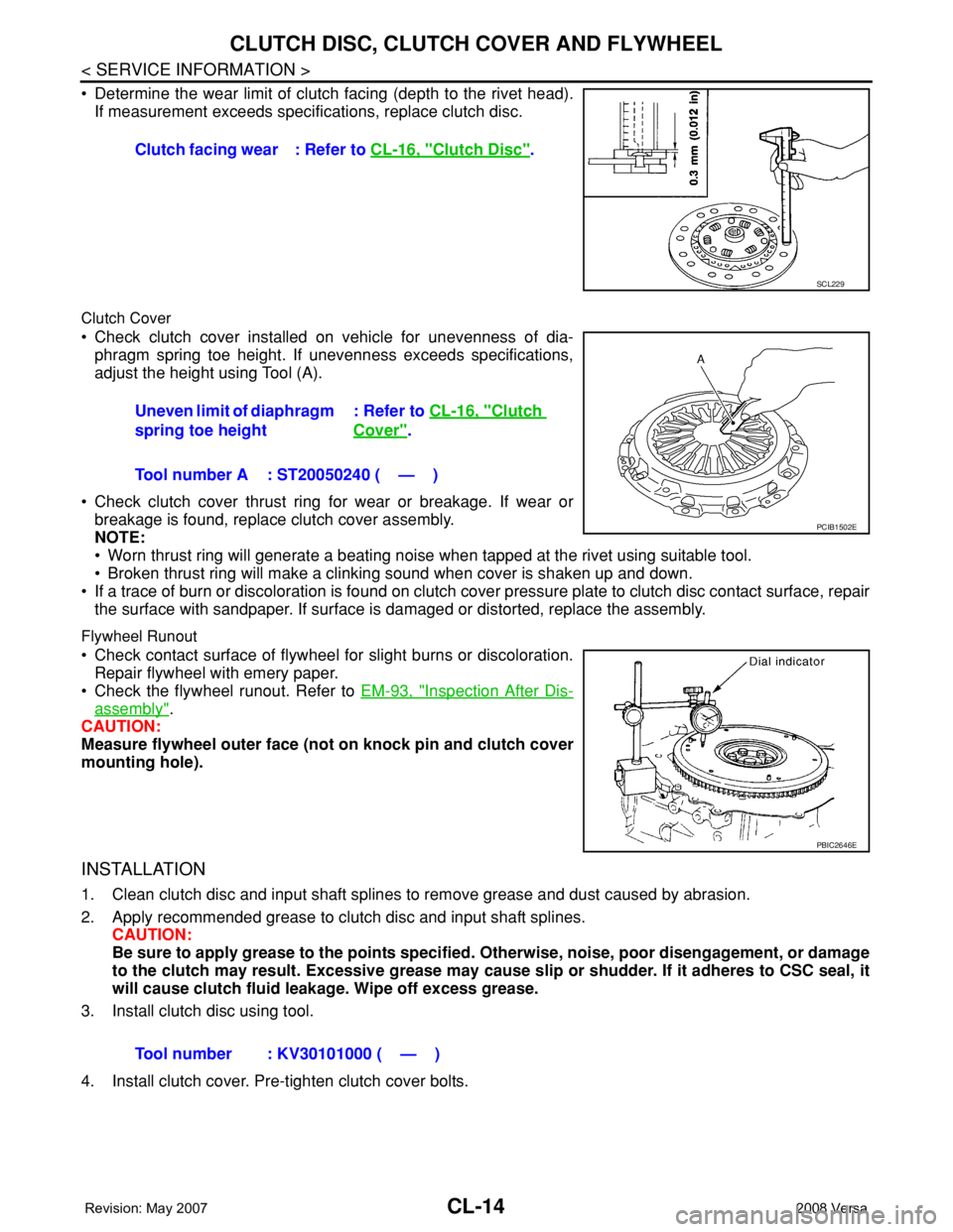
• Determine the wear limit of clutch facing (depth to the rivet head).
If measurement exceeds specifications, replace clutch disc.
Clutch Cover
• Check clutch cover installed on vehicle for unevenness of dia-
phragm spring toe height. If unevenness exceeds specifications,
adjust the height using Tool (A).
• Check clutch cover thrust ring for wear or breakage. If wear or
breakage is found, replace clutch cover assembly.
NOTE:
• Worn thrust ring will generate a beating noise when tapped at the rivet using suitable tool.
• Broken thrust ring will make a clinking sound when cover is shaken up and down.
• If a trace of burn or discoloration is found on clutch cover pressure plate to clutch disc contact surface, repair
the surface with sandpaper. If surface is damaged or distorted, replace the assembly.
Flywheel Runout
• Check contact surface of flywheel for slight burns or discoloration.
Repair flywheel with emery paper.
• Check the flywheel runout. Refer to EM-93, "
Inspection After Dis-
assembly".
CAUTION:
Measure flywheel outer face (not on knock pin and clutch cover
mounting hole).
INSTALLATION
1. Clean clutch disc and input shaft splines to remove grease and dust caused by abrasion.
2. Apply recommended grease to clutch disc and input shaft splines.
CAUTION:
Be sure to apply grease to the points specified. Otherwise, noise, poor disengagement, or damage
to the clutch may result. Excessive grease may cause slip or shudder. If it adheres to CSC seal, it
will cause clutch fluid leakage. Wipe off excess grease.
3. Install clutch disc using tool.
4. Install clutch cover. Pre-tighten clutch cover bolts.Clutch facing wear : Refer to CL-16, "
Clutch Disc".
SCL229
Uneven limit of diaphragm
spring toe height: Refer to CL-16, "Clutch
Cover".
Tool number A : ST20050240 ( — )
PCIB1502E
PBIC2646E
Tool number : KV30101000 ( — )
Page 816 of 2771
CLUTCH DISC, CLUTCH COVER AND FLYWHEEL
CL-15
< SERVICE INFORMATION >
D
E
F
G
H
I
J
K
L
MA
B
CL
N
O
P
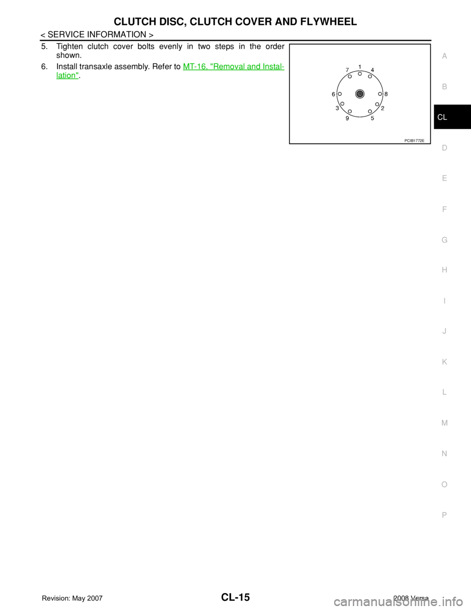
5. Tighten clutch cover bolts evenly in two steps in the order
shown.
6. Install transaxle assembly. Refer to MT-16, "
Removal and Instal-
lation".
PCIB1772E
Page 818 of 2771
CO-1
ENGINE
C
D
E
F
G
H
I
J
K
L
M
SECTION CO
A
CO
N
O
P
CONTENTS
ENGINE COOLING SYSTEM
SERVICE INFORMATION ............................2
PRECAUTIONS ...................................................2
Precaution for Supplemental Restraint System
(SRS) "AIR BAG" and "SEAT BELT PRE-TEN-
SIONER" ...................................................................
2
Precaution Necessary for Steering Wheel Rota-
tion After Battery Disconnect .....................................
2
Precaution for Liquid Gasket .....................................2
PREPARATION ...................................................4
Special Service Tool .................................................4
Commercial Service Tool ..........................................4
OVERHEATING CAUSE ANALYSIS ..................5
Troubleshooting Chart ...............................................5
COOLING SYSTEM ............................................7
Cooling Circuit ...........................................................7
ENGINE COOLANT ............................................8
Inspection ..................................................................8
Changing Engine Coolant .........................................8
RADIATOR .........................................................11
Component ..............................................................11
Removal and Installation .........................................11
Checking Radiator Cap ...........................................13
Checking Radiator ...................................................13
COOLING FAN ..................................................14
Component (Models with A/C) .................................14
Component (Models without A/C) ............................14
Removal and Installation .........................................15
DISASSEMBLY AND ASSEMBLY ..........................15
WATER PUMP ..................................................16
Component ..............................................................16
Removal and Installation .........................................16
THERMOSTAT ..................................................17
Component ..............................................................17
Removal and Installation .........................................17
WATER OUTLET AND WATER CONTROL
VALVE ...............................................................
19
Component ..............................................................19
Removal and Installation .........................................19
SERVICE DATA AND SPECIFICATIONS
(SDS) .................................................................
22
Standard and Limit ..................................................22
Page 819 of 2771
CO-2
< SERVICE INFORMATION >
PRECAUTIONS
SERVICE INFORMATION
PRECAUTIONS
Precaution for Supplemental Restraint System (SRS) "AIR BAG" and "SEAT BELT
PRE-TENSIONER"
INFOID:0000000001702522
The Supplemental Restraint System such as “AIR BAG” and “SEAT BELT PRE-TENSIONER”, used along
with a front seat belt, helps to reduce the risk or severity of injury to the driver and front passenger for certain
types of collision. This system includes seat belt switch inputs and dual stage front air bag modules. The SRS
system uses the seat belt switches to determine the front air bag deployment, and may only deploy one front
air bag, depending on the severity of a collision and whether the front occupants are belted or unbelted.
Information necessary to service the system safely is included in the SRS and SB section of this Service Man-
ual.
WARNING:
• To avoid rendering the SRS inoperative, which could increase the risk of personal injury or death in
the event of a collision which would result in air bag inflation, all maintenance must be performed by
an authorized NISSAN/INFINITI dealer.
• Improper maintenance, including incorrect removal and installation of the SRS, can lead to personal
injury caused by unintentional activation of the system. For removal of Spiral Cable and Air Bag
Module, see the SRS section.
• Do not use electrical test equipment on any circuit related to the SRS unless instructed to in this
Service Manual. SRS wiring harnesses can be identified by yellow and/or orange harnesses or har-
ness connectors.
Precaution Necessary for Steering Wheel Rotation After Battery Disconnect
INFOID:0000000001702523
NOTE:
• This Procedure is applied only to models with Intelligent Key system and NATS (NISSAN ANTI-THEFT SYS-
TEM).
• Remove and install all control units after disconnecting both battery cables with the ignition knob in the
″LOCK″ position.
• Always use CONSULT-III to perform self-diagnosis as a part of each function inspection after finishing work.
If DTC is detected, perform trouble diagnosis according to self-diagnostic results.
For models equipped with the Intelligent Key system and NATS, an electrically controlled steering lock mech-
anism is adopted on the key cylinder.
For this reason, if the battery is disconnected or if the battery is discharged, the steering wheel will lock and
steering wheel rotation will become impossible.
If steering wheel rotation is required when battery power is interrupted, follow the procedure below before
starting the repair operation.
OPERATION PROCEDURE
1. Connect both battery cables.
NOTE:
Supply power using jumper cables if battery is discharged.
2. Use the Intelligent Key or mechanical key to turn the ignition switch to the ″ACC″ position. At this time, the
steering lock will be released.
3. Disconnect both battery cables. The steering lock will remain released and the steering wheel can be
rotated.
4. Perform the necessary repair operation.
5. When the repair work is completed, return the ignition switch to the ″LOCK″ position before connecting
the battery cables. (At this time, the steering lock mechanism will engage.)
6. Perform a self-diagnosis check of all control units using CONSULT-III.
Precaution for Liquid GasketINFOID:0000000001702524
REMOVAL OF LIQUID GASKET SEALING
• After removing nuts and bolts, separate the mating surface, using Tool and remove old liquid gasket sealing.
Page 823 of 2771

CO-6
< SERVICE INFORMATION >
OVERHEATING CAUSE ANALYSIS
Except cool-
ing system
parts mal-
function— Overload on engineAbusive drivingHigh engine rpm under no
load
Driving in low gear for ex-
tended time
Driving at extremely high
speed
Power train system mal-
function
— Installed improper size
wheels and tires
Dragging brakes
Improper ignition timing
Blocked or restricted air
flowBlocked bumper —
Installed front bumper fas-
cia cover
— Blocked radiator grille
Mud contamination or paper
clogging
Blocked radiator
—
Blocked air flow Blocked condenser
Installed large fog lamp Symptom Check items
Page 840 of 2771
CVT-1
TRANSMISSION/TRANSAXLE
D
E
F
G
H
I
J
K
L
M
SECTION CVT
A
B
CVT
N
O
P
CONTENTS
CVT
SERVICE INFORMATION ............................5
INDEX FOR DTC .................................................5
Alphabetical Index .....................................................5
DTC No. Index ..........................................................5
PRECAUTIONS ...................................................7
Precaution for Supplemental Restraint System
(SRS) "AIR BAG" and "SEAT BELT PRE-TEN-
SIONER" ...................................................................
7
Precaution Necessary for Steering Wheel Rota-
tion After Battery Disconnect .....................................
7
Precaution for On Board Diagnosis (OBD) System
of CVT and Engine ....................................................
7
Service After Replacing TCM and Transaxle As-
sembly .......................................................................
8
Removal and Installation Procedure for CVT Unit
Connector ..................................................................
9
Precaution ...............................................................10
Service Notice or Precaution ...................................11
PREPARATION ..................................................12
Special Service Tool ...............................................12
Commercial Service Tool ........................................12
CVT FLUID .........................................................13
Checking CVT Fluid ................................................13
Changing CVT Fluid ................................................14
CVT Fluid Cooler Cleaning .....................................14
CVT SYSTEM .....................................................18
Cross-Sectional View - RE0F08A ...........................18
Control System ........................................................19
Hydraulic Control System ........................................20
TCM Function ..........................................................20
CAN Communication ...............................................21
Input/Output Signal of TCM .....................................22
Line Pressure and Secondary Pressure Control .....22
Shift Control ............................................................23
Lock-up and Select Control .....................................24
Control Valve ...........................................................25
ON BOARD DIAGNOSTIC (OBD) SYSTEM ....26
Introduction ..............................................................26
OBD-II Function for CVT System ............................26
One or Two Trip Detection Logic of OBD-II .............26
OBD-II Diagnostic Trouble Code (DTC) ..................26
Malfunction Indicator Lamp (MIL) ............................27
TROUBLE DIAGNOSIS ....................................29
DTC Inspection Priority Chart ..................................29
Fail-Safe ..................................................................29
How to Perform Trouble Diagnosis for Quick and
Accurate Repair .......................................................
30
CVT Electrical Parts Location ..................................35
Circuit Diagram ........................................................36
Inspections before Trouble Diagnosis .....................36
Road Test ................................................................40
Check before Engine Is Started ...............................41
Check at Idle ............................................................41
Cruise Test ..............................................................43
Vehicle Speed When Shifting Gears .......................45
TCM Terminal and Reference Value .......................45
CONSULT-III Function (TRANSMISSION) ..............47
Diagnosis Procedure without CONSULT-III ............55
DTC U1000 CAN COMMUNICATION LINE .....56
Description ...............................................................56
On Board Diagnosis Logic .......................................56
Possible Cause ........................................................56
DTC Confirmation Procedure ..................................56
Wiring Diagram - CVT - CAN ...................................57
Diagnosis Procedure ...............................................58
DTC U1010 TRANSMISSION CONTROL
MODULE (CAN) ................................................
59
Description ...............................................................59
On Board Diagnosis Logic .......................................59
Possible Cause ........................................................59
DTC Confirmation Procedure ..................................59
Diagnosis Procedure ...............................................59
DTC P0615 START SIGNAL CIRCUIT .............60