2008 NISSAN LATIO tow
[x] Cancel search: towPage 1758 of 2771
CYLINDER BLOCK
EM-81
< SERVICE INFORMATION >
C
D
E
F
G
H
I
J
K
L
MA
EM
N
P O
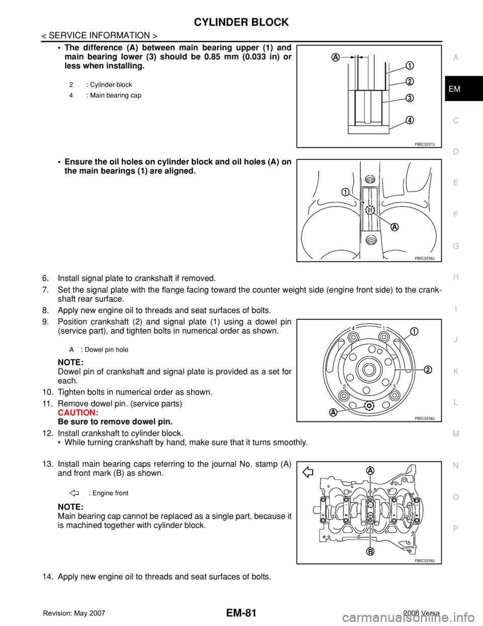
• The difference (A) between main bearing upper (1) and
main bearing lower (3) should be 0.85 mm (0.033 in) or
less when installing.
• Ensure the oil holes on cylinder block and oil holes (A) on
the main bearings (1) are aligned.
6. Install signal plate to crankshaft if removed.
7. Set the signal plate with the flange facing toward the counter weight side (engine front side) to the crank-
shaft rear surface.
8. Apply new engine oil to threads and seat surfaces of bolts.
9. Position crankshaft (2) and signal plate (1) using a dowel pin
(service part), and tighten bolts in numerical order as shown.
NOTE:
Dowel pin of crankshaft and signal plate is provided as a set for
each.
10. Tighten bolts in numerical order as shown.
11. Remove dowel pin. (service parts)
CAUTION:
Be sure to remove dowel pin.
12. Install crankshaft to cylinder block.
• While turning crankshaft by hand, make sure that it turns smoothly.
13. Install main bearing caps referring to the journal No. stamp (A)
and front mark (B) as shown.
NOTE:
Main bearing cap cannot be replaced as a single part, because it
is machined together with cylinder block.
14. Apply new engine oil to threads and seat surfaces of bolts.
2 : Cylinder block
4 : Main bearing cap
PBIC3237J
PBIC3236J
A : Dowel pin hole
PBIC3238J
: Engine front
PBIC3239J
Page 1762 of 2771
CYLINDER BLOCK
EM-85
< SERVICE INFORMATION >
C
D
E
F
G
H
I
J
K
L
MA
EM
N
P O
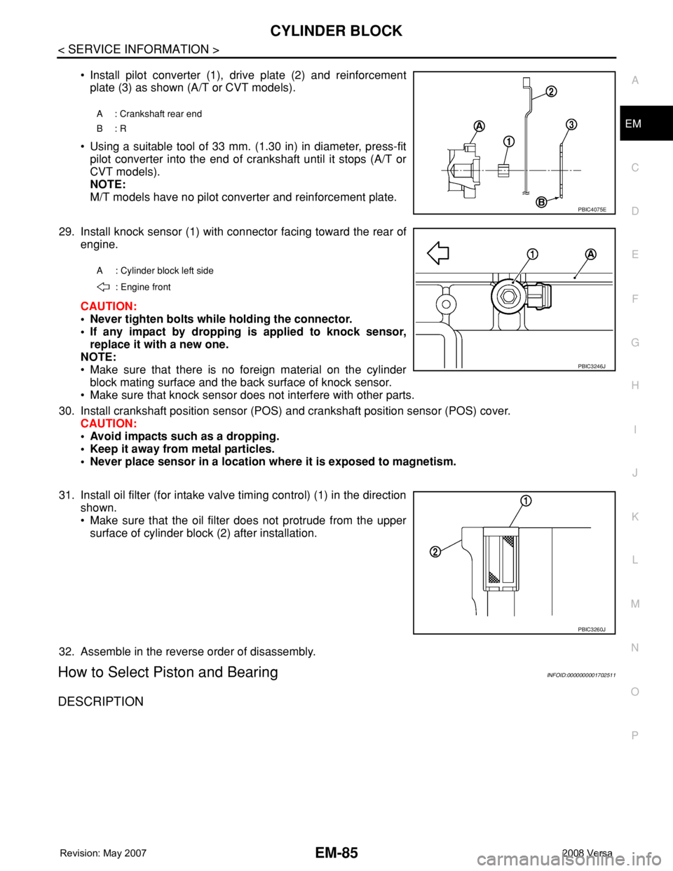
• Install pilot converter (1), drive plate (2) and reinforcement
plate (3) as shown (A/T or CVT models).
• Using a suitable tool of 33 mm. (1.30 in) in diameter, press-fit
pilot converter into the end of crankshaft until it stops (A/T or
CVT models).
NOTE:
M/T models have no pilot converter and reinforcement plate.
29. Install knock sensor (1) with connector facing toward the rear of
engine.
CAUTION:
• Never tighten bolts while holding the connector.
• If any impact by dropping is applied to knock sensor,
replace it with a new one.
NOTE:
• Make sure that there is no foreign material on the cylinder
block mating surface and the back surface of knock sensor.
• Make sure that knock sensor does not interfere with other parts.
30. Install crankshaft position sensor (POS) and crankshaft position sensor (POS) cover.
CAUTION:
• Avoid impacts such as a dropping.
• Keep it away from metal particles.
• Never place sensor in a location where it is exposed to magnetism.
31. Install oil filter (for intake valve timing control) (1) in the direction
shown.
• Make sure that the oil filter does not protrude from the upper
surface of cylinder block (2) after installation.
32. Assemble in the reverse order of disassembly.
How to Select Piston and BearingINFOID:0000000001702511
DESCRIPTION
A : Crankshaft rear end
B: R
PBIC4075E
A : Cylinder block left side
: Engine front
PBIC3246J
PBIC3260J
Page 1832 of 2771
FL-12
< SERVICE INFORMATION >
FUEL TANK
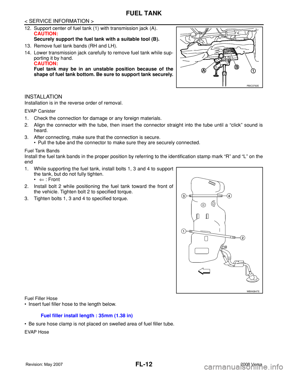
12. Support center of fuel tank (1) with transmission jack (A).
CAUTION:
Securely support the fuel tank with a suitable tool (B).
13. Remove fuel tank bands (RH and LH).
14. Lower transmission jack carefully to remove fuel tank while sup-
porting it by hand.
CAUTION:
Fuel tank may be in an unstable position because of the
shape of fuel tank bottom. Be sure to support tank securely.
INSTALLATION
Installation is in the reverse order of removal.
EVAP Canister
1. Check the connection for damage or any foreign materials.
2. Align the connector with the tube, then insert the connector straight into the tube until a “click” sound is
heard.
3. After connecting, make sure that the connection is secure.
• Pull the tube and the connector to make sure they are securely connected.
Fuel Tank Bands
Install the fuel tank bands in the proper position by referring to the identification stamp mark “R” and “L” on the
end
1. While supporting the fuel tank, install bolts 1, 3 and 4 to support
the tank, but do not fully tighten.
• ⇐ : Front
2. Install bolt 2 while positioning the fuel tank toward the front of
the vehicle. Tighten bolt 2 to specified torque.
3. Tighten bolts 1, 3 and 4 to specified torque.
Fuel Filler Hose
• Insert fuel filler hose to the length below.
• Be sure hose clamp is not placed on swelled area of fuel filler tube.
EVAP Hose
PBIC3792E
WBIA0847E
Fuel filler install length : 35mm (1.38 in)
Page 1852 of 2771
GI-1
GENERAL INFORMATION
C
D
E
F
G
H
I
J
K
L
MB
GI
SECTION GI
N
O
P
CONTENTS
GENERAL INFORMATION
SERVICE INFORMATION ............................2
PRECAUTIONS ...................................................2
Description ................................................................2
Precaution for Supplemental Restraint System
(SRS) "AIR BAG" and "SEAT BELT PRE-TEN-
SIONER" ...................................................................
2
Precaution Necessary for Steering Wheel Rota-
tion After Battery Disconnect .....................................
2
General Precaution ...................................................3
Precaution for Three Way Catalyst ...........................4
Precaution for Fuel (Unleaded Regular Gasoline
Recommended) .........................................................
4
Precaution for Multiport Fuel Injection System or
Engine Control System .............................................
5
Precaution for Hoses .................................................5
Precaution for Engine Oils ........................................6
Precaution for Air Conditioning .................................6
HOW TO USE THIS MANUAL ............................7
Description ................................................................7
Terms ........................................................................7
Units ..........................................................................7
Contents ....................................................................7
Relation between Illustrations and Descriptions .......8
Component ................................................................8
How to Follow Trouble Diagnosis ..............................9
How to Read Wiring Diagram ..................................13
Abbreviations ..........................................................20
SERVICE INFORMATION FOR ELECTRICAL
INCIDENT ...........................................................
22
How to Check Terminal ...........................................22
How to Perform Efficient Diagnosis for an Electri-
cal Incident ..............................................................
25
Control Units and Electrical Parts ............................32
CONSULT-III CHECKING SYSTEM .................35
Description ...............................................................35
Function and System Application ............................35
CONSULT-III Data Link Connector (DLC) Circuit ....36
LIFTING POINT .................................................38
Special Service Tool ................................................38
Garage Jack and Safety Stand and 2-Pole Lift .......38
Board-On Lift ...........................................................39
TOW TRUCK TOWING .....................................40
Tow Truck Towing ...................................................40
Vehicle Recovery (Freeing a Stuck Vehicle) ...........40
TIGHTENING TORQUE OF STANDARD
BOLTS ...............................................................
41
Tightening Torque Table .........................................41
RECOMMENDED CHEMICAL PRODUCTS
AND SEALANTS ...............................................
42
Recommended Chemical Product and Sealant .......42
IDENTIFICATION INFORMATION ....................43
Model Variation ........................................................43
Dimensions ..............................................................46
Wheels & Tires ........................................................46
TERMINOLOGY ................................................47
SAE J1930 Terminology List ...................................47
Page 1891 of 2771
GI-40
< SERVICE INFORMATION >
TOW TRUCK TOWING
TOW TRUCK TOWING
Tow Truck TowingINFOID:0000000001702452
CAUTION:
• All applicable local laws regarding the towing operation must be obeyed.
• It is necessary to use proper towing equipment to avoid possible damage to the vehicle during tow-
ing operation. Towing is in accordance with Towing Procedure Manual at dealer.
• Always attach safety chains before towing.
• When towing, make sure that the transmission, steering system and power train are in good order. If
any unit is damaged, dollies must be used.
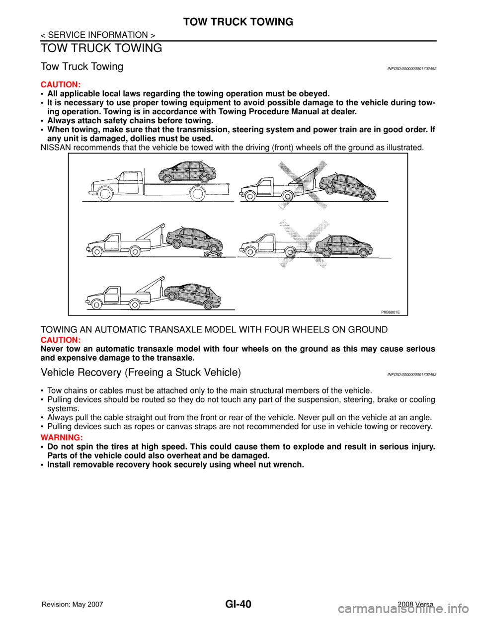
NISSAN recommends that the vehicle be towed with the driving (front) wheels off the ground as illustrated.
TOWING AN AUTOMATIC TRANSAXLE MODEL WITH FOUR WHEELS ON GROUND
CAUTION:
Never tow an automatic transaxle model with four wheels on the ground as this may cause serious
and expensive damage to the transaxle.
Vehicle Recovery (Freeing a Stuck Vehicle)INFOID:0000000001702453
• Tow chains or cables must be attached only to the main structural members of the vehicle.
• Pulling devices should be routed so they do not touch any part of the suspension, steering, brake or cooling
systems.
• Always pull the cable straight out from the front or rear of the vehicle. Never pull on the vehicle at an angle.
• Pulling devices such as ropes or canvas straps are not recommended for use in vehicle towing or recovery.
WARNING:
• Do not spin the tires at high speed. This could cause them to explode and result in serious injury.
Parts of the vehicle could also overheat and be damaged.
• Install removable recovery hook securely using wheel nut wrench.
PIIB6801E
Page 1944 of 2771
FRONT DOOR GLASS AND REGULATOR
GW-43
< SERVICE INFORMATION >
C
D
E
F
G
H
J
K
L
MA
B
GW
N
O
P
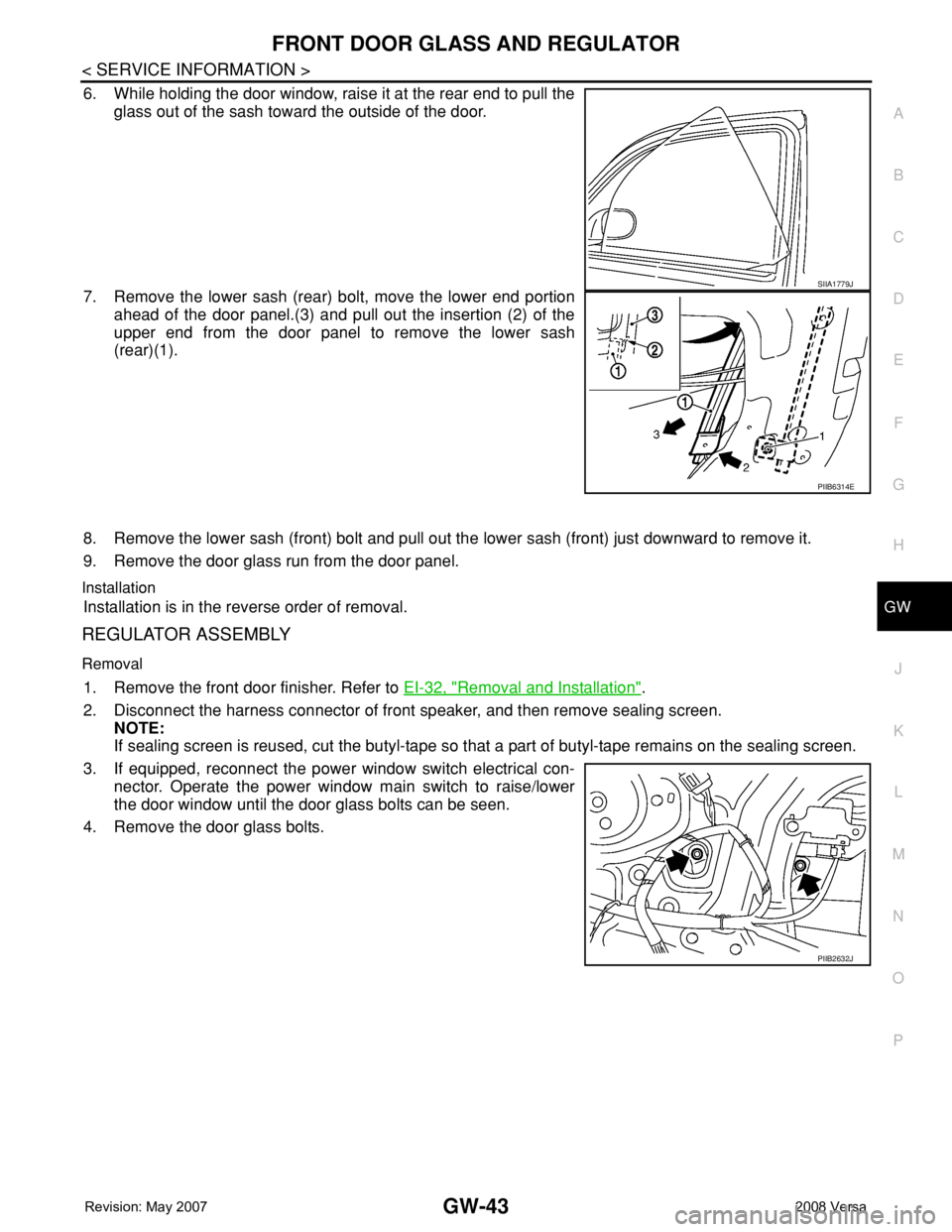
6. While holding the door window, raise it at the rear end to pull the
glass out of the sash toward the outside of the door.
7. Remove the lower sash (rear) bolt, move the lower end portion
ahead of the door panel.(3) and pull out the insertion (2) of the
upper end from the door panel to remove the lower sash
(rear)(1).
8. Remove the lower sash (front) bolt and pull out the lower sash (front) just downward to remove it.
9. Remove the door glass run from the door panel.
Installation
Installation is in the reverse order of removal.
REGULATOR ASSEMBLY
Removal
1. Remove the front door finisher. Refer to EI-32, "Removal and Installation".
2. Disconnect the harness connector of front speaker, and then remove sealing screen.
NOTE:
If sealing screen is reused, cut the butyl-tape so that a part of butyl-tape remains on the sealing screen.
3. If equipped, reconnect the power window switch electrical con-
nector. Operate the power window main switch to raise/lower
the door window until the door glass bolts can be seen.
4. Remove the door glass bolts.
SIIA1779J
PIIB6314E
PIIB2632J
Page 1948 of 2771
REAR DOOR GLASS AND REGULATOR
GW-47
< SERVICE INFORMATION >
C
D
E
F
G
H
J
K
L
MA
B
GW
N
O
P
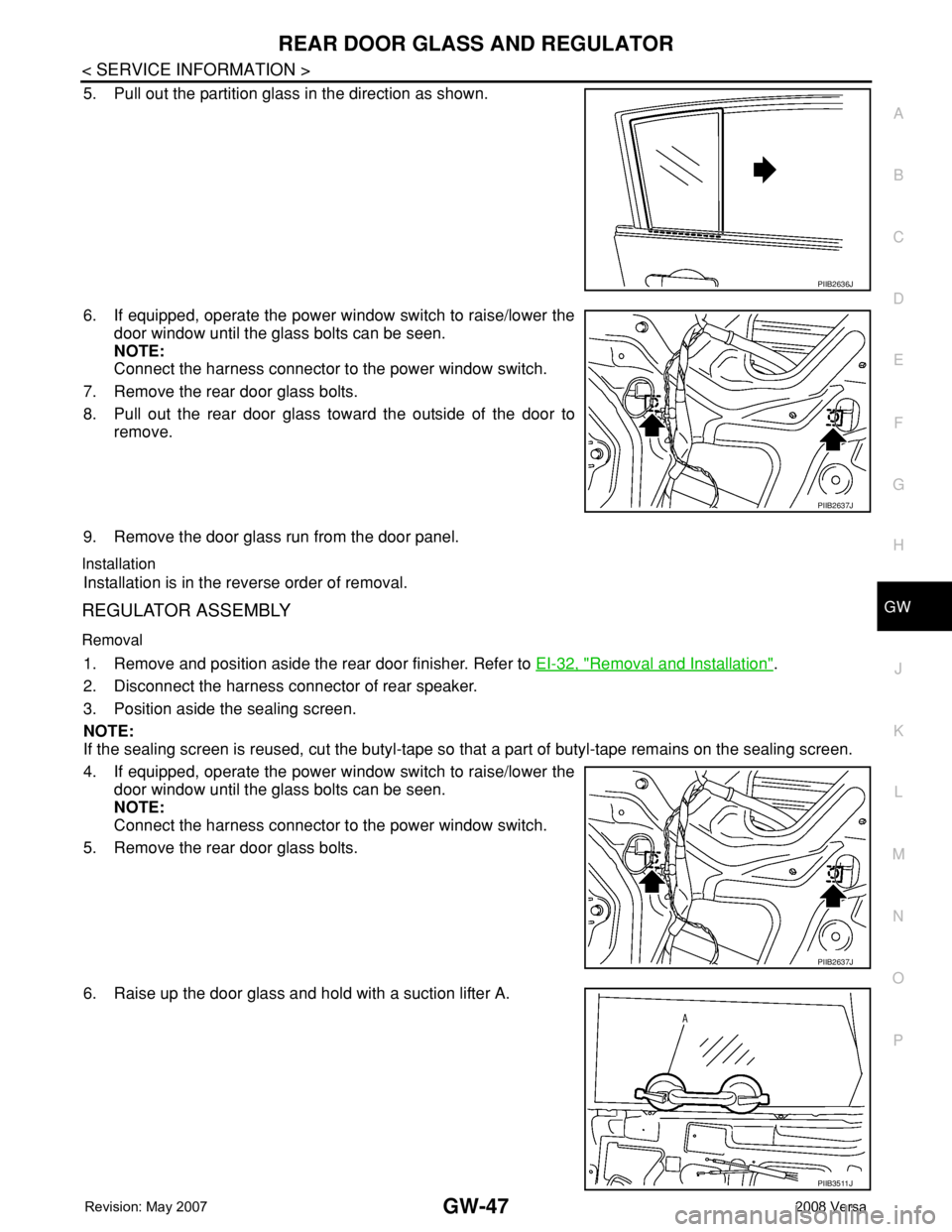
5. Pull out the partition glass in the direction as shown.
6. If equipped, operate the power window switch to raise/lower the
door window until the glass bolts can be seen.
NOTE:
Connect the harness connector to the power window switch.
7. Remove the rear door glass bolts.
8. Pull out the rear door glass toward the outside of the door to
remove.
9. Remove the door glass run from the door panel.
Installation
Installation is in the reverse order of removal.
REGULATOR ASSEMBLY
Removal
1. Remove and position aside the rear door finisher. Refer to EI-32, "Removal and Installation".
2. Disconnect the harness connector of rear speaker.
3. Position aside the sealing screen.
NOTE:
If the sealing screen is reused, cut the butyl-tape so that a part of butyl-tape remains on the sealing screen.
4. If equipped, operate the power window switch to raise/lower the
door window until the glass bolts can be seen.
NOTE:
Connect the harness connector to the power window switch.
5. Remove the rear door glass bolts.
6. Raise up the door glass and hold with a suction lifter A.
PIIB2636J
PIIB2637J
PIIB2637J
PIIB3511J
Page 2158 of 2771
HEADLAMP (FOR USA)
LT-21
< SERVICE INFORMATION >
C
D
E
F
G
H
I
J
L
MA
B
LT
N
O
P
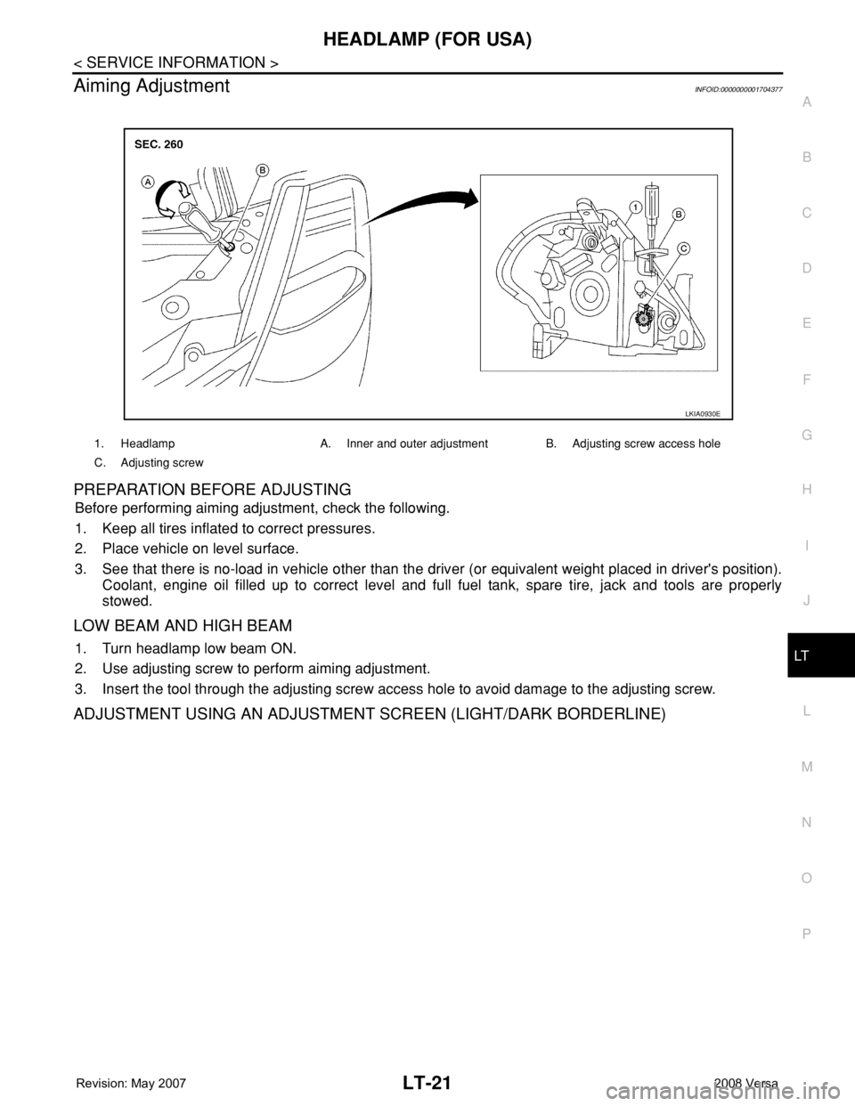
Aiming AdjustmentINFOID:0000000001704377
PREPARATION BEFORE ADJUSTING
Before performing aiming adjustment, check the following.
1. Keep all tires inflated to correct pressures.
2. Place vehicle on level surface.
3. See that there is no-load in vehicle other than the driver (or equivalent weight placed in driver's position).
Coolant, engine oil filled up to correct level and full fuel tank, spare tire, jack and tools are properly
stowed.
LOW BEAM AND HIGH BEAM
1. Turn headlamp low beam ON.
2. Use adjusting screw to perform aiming adjustment.
3. Insert the tool through the adjusting screw access hole to avoid damage to the adjusting screw.
ADJUSTMENT USING AN ADJUSTMENT SCREEN (LIGHT/DARK BORDERLINE)
1. Headlamp A. Inner and outer adjustment B. Adjusting screw access hole
C. Adjusting screw
LKIA0930E