Page 2280 of 2771

MA-20
< SERVICE INFORMATION >
CHASSIS AND BODY MAINTENANCE
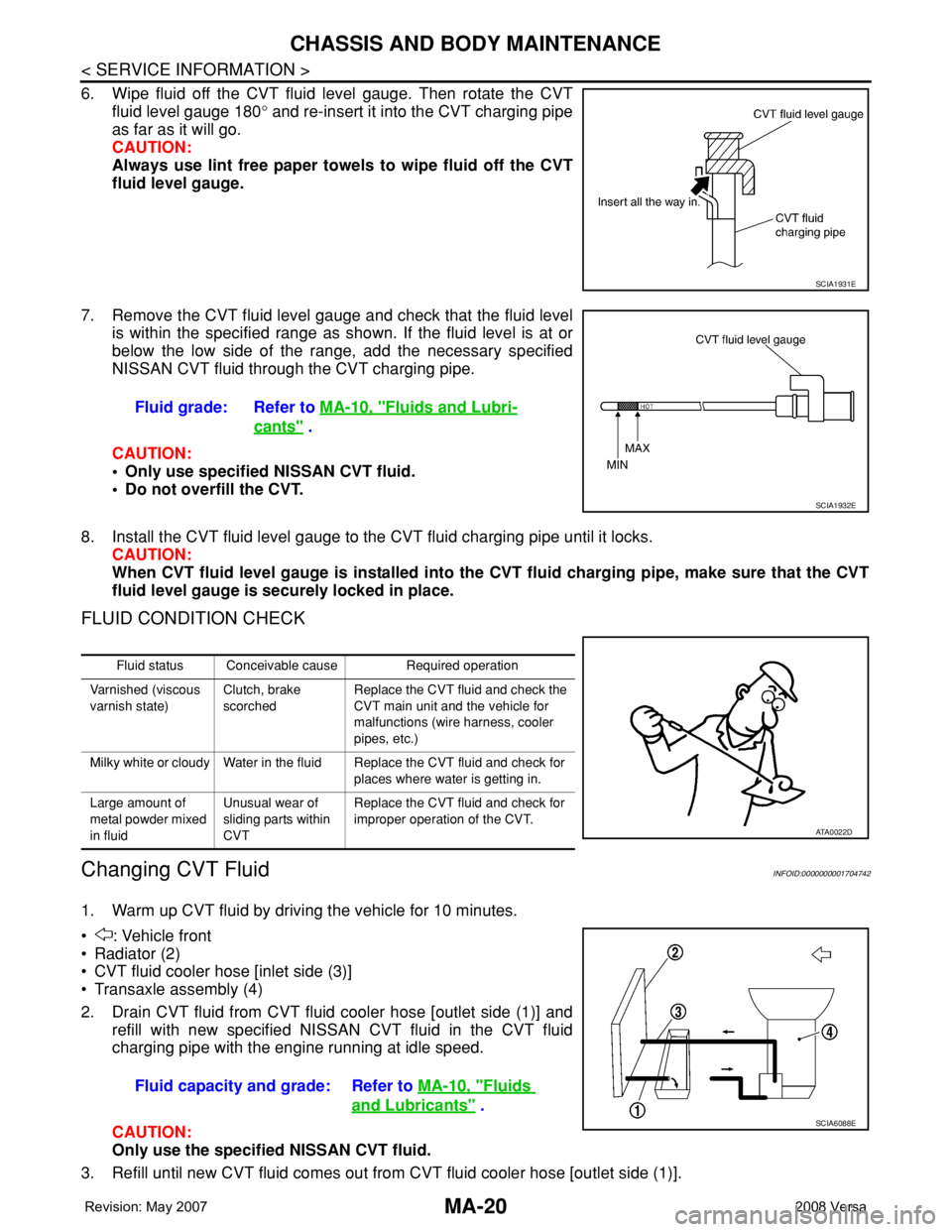
6. Wipe fluid off the CVT fluid level gauge. Then rotate the CVT
fluid level gauge 180° and re-insert it into the CVT charging pipe
as far as it will go.
CAUTION:
Always use lint free paper towels to wipe fluid off the CVT
fluid level gauge.
7. Remove the CVT fluid level gauge and check that the fluid level
is within the specified range as shown. If the fluid level is at or
below the low side of the range, add the necessary specified
NISSAN CVT fluid through the CVT charging pipe.
CAUTION:
• Only use specified NISSAN CVT fluid.
• Do not overfill the CVT.
8. Install the CVT fluid level gauge to the CVT fluid charging pipe until it locks.
CAUTION:
When CVT fluid level gauge is installed into the CVT fluid charging pipe, make sure that the CVT
fluid level gauge is securely locked in place.
FLUID CONDITION CHECK
Changing CVT FluidINFOID:0000000001704742
1. Warm up CVT fluid by driving the vehicle for 10 minutes.
• : Vehicle front
• Radiator (2)
• CVT fluid cooler hose [inlet side (3)]
• Transaxle assembly (4)
2. Drain CVT fluid from CVT fluid cooler hose [outlet side (1)] and
refill with new specified NISSAN CVT fluid in the CVT fluid
charging pipe with the engine running at idle speed.
CAUTION:
Only use the specified NISSAN CVT fluid.
3. Refill until new CVT fluid comes out from CVT fluid cooler hose [outlet side (1)].
SCIA1931E
Fluid grade: Refer to MA-10, "Fluids and Lubri-
cants" .
SCIA1932E
Fluid status Conceivable cause Required operation
Varnished (viscous
varnish state)Clutch, brake
scorchedReplace the CVT fluid and check the
CVT main unit and the vehicle for
malfunctions (wire harness, cooler
pipes, etc.)
Milky white or cloudy Water in the fluid Replace the CVT fluid and check for
places where water is getting in.
Large amount of
metal powder mixed
in fluidUnusual wear of
sliding parts within
CVTReplace the CVT fluid and check for
improper operation of the CVT.
ATA0022D
Fluid capacity and grade: Refer to MA-10, "Fluids
and Lubricants" .SCIA6088E
Page 2303 of 2771

AIR BREATHER HOSE
MT-15
< SERVICE INFORMATION >
D
E
F
G
H
I
J
K
L
MA
B
MT
N
O
P
AIR BREATHER HOSE
Removal and InstallationINFOID:0000000001703140
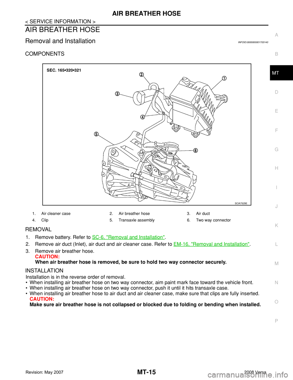
COMPONENTS
REMOVAL
1. Remove battery. Refer to SC-6, "Removal and Installation".
2. Remove air duct (Inlet), air duct and air cleaner case. Refer to EM-16, "
Removal and Installation".
3. Remove air breather hose.
CAUTION:
When air breather hose is removed, be sure to hold two way connector securely.
INSTALLATION
Installation is in the reverse order of removal.
• When installing air breather hose on two way connector, aim paint mark face toward the vehicle front.
• When installing air breather hose on two way connector, push it until it hits transaxle case.
• When installing air breather hose to air duct and air cleaner case, make sure that clips are fully inserted.
CAUTION:
Make sure air breather hose is not collapsed or blocked due to folding or bending when installed.
1. Air cleaner case 2. Air breather hose 3. Air duct
4. Clip 5. Transaxle assembly 6. Two way connector
SCIA7629E
Page 2400 of 2771
MTC-62
< SERVICE INFORMATION >
BLOWER MOTOR
BLOWER MOTOR
Removal and InstallationINFOID:0000000001704314
REMOVAL
1. Remove instrument panel and pad. Refer to IP-10.
2. Remove side ventilator duct (right). Refer to MTC-69, "
Removal and Installation".
3. Disconnect blower motor connector (1).
4. Push the flange holding hook (A) toward the blower motor (2),
then rotate the blower motor (2) clockwise and remove it from
the A/C unit assembly.
CAUTION:
When blower fan and blower motor are assembled, the bal-
ance is adjusted, do not disassemble to replace the individ-
ual parts.
INSTALLATION
Installation is in the reverse order of removal.
CAUTION:
Rotate the blower motor until the blower motor flange holding hook locks securely in A/C unit assem-
bly.
LJIA0199E
Page 2402 of 2771
MTC-64
< SERVICE INFORMATION >
AIR MIX DOOR
AIR MIX DOOR
Air Mix Door Cable AdjustmentINFOID:0000000001704316
1. Remove steering member. Refer to MTC-58.
2. Remove outer cable of air mix door cable (1) from clamp (A).
3. Set temperature control dial to full cold position.
4. Push air mix door lever (2) in the direction shown by arrow, and
then carefully pull outer cable toward controller side, and install
clamp (A).
5. Operate temperature control dial to insure that inner cable
moves smoothly.
CAUTION:
When clamping the outer cable, do not move the inner
cable.
SJIA1150E
Page 2420 of 2771

MTC-82
< SERVICE INFORMATION >
REFRIGERANT LINES
INSTALLATION
Installation is in the reverse order of removal.
CAUTION:
• Replace O-rings of refrigerant pressure sensor with a new one, and apply compressor oil when
installing.
• When recharging refrigerant, check for leaks.
Removal and Installation of CondenserINFOID:0000000001704329
REMOVAL
1. Remove the three upper headlamp bolts to reposition the headlamps out of the way
2. Remove the radiator core support upper. Refer to BL-19
.
3. Remove high-pressure flexible hose and high-pressure pipe from condenser. Refer to MTC-80, "
Removal
and Installation of High-pressure Flexible Hose" and MTC-81, "Removal and Installation of High-pres-
sure Pipe" .
CAUTION:
Cap or wrap the joint of the pipe with suitable material such as vinyl tape to avoid the entry of air.
4. Disconnect refrigerant pressure sensor connector.
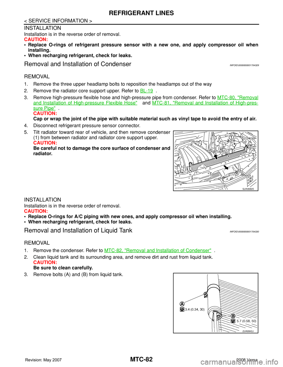
5. Tilt radiator toward rear of vehicle, and then remove condenser
(1) from between radiator and radiator core support upper.
CAUTION:
Be careful not to damage the core surface of condenser and
radiator.
INSTALLATION
Installation is in the reverse order of removal.
CAUTION:
• Replace O-rings for A/C piping with new ones, and apply compressor oil when installing.
• When recharging refrigerant, check for leaks.
Removal and Installation of Liquid TankINFOID:0000000001704330
REMOVAL
1. Remove the condenser. Refer to MTC-82, "Removal and Installation of Condenser" .
2. Clean liquid tank and its surrounding area, and remove dirt and rust from liquid tank.
CAUTION:
Be sure to clean carefully.
3. Remove bolts (A) and (B) from liquid tank.
SJIA0682E
ZJIA0842J
Page 2509 of 2771
PRECAUTIONS
PS-3
< SERVICE INFORMATION >
C
D
E
F
H
I
J
K
L
MA
B
PS
N
O
P
- Before disassembly, thoroughly clean the outside of the unit.
- Disassembly should be done in a clean work area. It is important to prevent the internal parts from becoming
contaminated by dirt or other foreign matter.
- For easier and proper assembly, place disassembled parts in order on a parts rack.
- Use nylon cloth or paper towels to clean the parts; common shop rags can leave lint that might interfere with
their operation.
- Do not reuse non-reusable parts.
- Before assembling, apply the specified grease to the directed parts.
Page 2542 of 2771

RF-12
< FUNCTION DIAGNOSIS >
TROUBLE DIAGNOSIS
• the sunroof motor is removed from the sunroof assembly and the glass panel position is changed.
RE-TEACHING PROCEDURE
1. Using the UP/CLOSE switch, move the sunroof toward the tilt position until it stops.
2. Release the UP/CLOSE switch.
3. Press the UP/CLOSE switch again and continuously hold. The sunroof will begin to move in about 10 sec-
onds.
4. Continue to hold the UP/CLOSE switch while the sunroof moves in a jogging motion to the full tilt position.
When the sunroof reaches the full tilt position, it will back up a few millimeters and stop.
5. Release the UP/CLOSE switch.
6. Within 5 seconds of releasing the UP/CLOSE switch, press and hold the UP/CLOSE switch again. The
sunroof will move to the full open position and back to the closed position.
NOTE:
If the UP/CLOSE switch is released anytime during this teaching process, all learned profile data will be dis-
carded and the procedure will have to be started over.
7. Release the UP/CLOSE switch. Do not disconnect power for at least two seconds. The sunroof is now re-
taught.
CAN Communication System DescriptionINFOID:0000000001704193
Refer to LAN-6 .
Page 2625 of 2771
REAR SEAT
SE-17
< SERVICE INFORMATION >
C
D
E
F
G
H
J
K
L
MA
B
SE
N
O
P
1. Install the rear seatback side bracket in the vehicle.
2. Temporarily tighten the seatback assembly and rear seatback side bracket.
3. Lift to fold up seatback assembly. Be sure to lock seatback assembly to rear seat striker.
4. Tighten the bolt.
NOTE:
Confirm that side hinge bracket location pin is set to the hole on the seatback backside.
Disassembly and AssemblyINFOID:0000000001704268
60:40 SPLIT FOLD DOWN SEAT - HATCHBACK
Disassembly of Armrest
1. Fold up the backside of the seatback trim and then remove the
armrest nuts.
2. Push the armrest toward left side while pulling backward to
remove.
3. Remove the rear seat bushing, and then remove the armrest
hinge cover by pulling it backward.
PIIB2484J
PIIB2913J
PIIB2915J
PIIB6507E