Page 586 of 2771
BL-152
< SERVICE INFORMATION >
FRONT DOOR LOCK
15. Remove the door lock assembly bolts.
16. Slide the outside handle bracket toward the rear of the vehicle,
and remove the assembly.
17. If equipped, disconnect the door lock assembly electrical connector.
18. Separate the outside handle cable from the outside handle
bracket.
INSTALLATION
Installation is in the reverse order of removal.
CAUTION:
• To install each rod, be sure to rotate the rod holder until a click is felt.
• When installing door lock assembly, be careful when rotating the outside handle cable as shown in
the figure.
- Place the outside handle bracket cable on the inside of door
lock assembly before installing. 5.8 N·m (0.6 kg-m, 51.4 in-lb)
PIIB6527E
PIIB6528E
PIIB5815E
PIIB6529E
Page 587 of 2771
REAR DOOR LOCK
BL-153
< SERVICE INFORMATION >
C
D
E
F
G
H
J
K
L
MA
B
BL
N
O
P
REAR DOOR LOCK
Component Parts LocationINFOID:0000000001704049
Removal and InstallationINFOID:0000000001704050
REMOVAL
1. Remove the partition glass. Refer to GW-46 .
2. Support door glass while lifting it up to the door window completely closed position.
3. Remove inside handle bolt, slide handle toward rear of vehicle,
disconnect it from the door panel, and remove the inside handle.
4. Disconnect the inside handle and lock knob cables from the
inside handle.
CAUTION:
During removal and installation, do not to bend the ends of
the lock knob cable and inside handle cable.
1. Rear door 2. Inside handle 3. Inside handle cable
4. Door lock assembly 5. TORX bolt (T30) 6. Outside handle cable
7. Grommet 8. TORX bolt (T30) 9. Rear gasket
10. Outside handle escutcheon 11. Outside handle 12. Front gasket
13. Lock knob cable 14. Outside handle bracket
PIIB6530E
PIIB6524E
PIIB6525E
Page 588 of 2771
BL-154
< SERVICE INFORMATION >
REAR DOOR LOCK
5. Remove the door side grommet, and the outside handle
escutcheon screw.
6. Pull the outside handle forward (1), while removing outside han-
dle escutcheon (2).
7. Pull outside door handle forward (1), and slide it toward the rear
of the vehicle to remove (2).
8. Remove the front and rear gaskets.
9. Remove the door lock assembly screws.
PIIB5808E
PIIB5809E
PIIB5810E
PIIB6526E
: 5.8 N·m (0.6 kg-m, 51.4 in-lb)
PIIB6527E
Page 589 of 2771
REAR DOOR LOCK
BL-155
< SERVICE INFORMATION >
C
D
E
F
G
H
J
K
L
MA
B
BL
N
O
P
10. Slide the outside handle bracket toward the rear of vehicle,
remove the outside handle bracket and the door lock assembly.
11. If equipped, disconnect the door lock assembly electrical connector.
12. Disconnect the outside handle cable from the outside handle
bracket.
INSTALLATION
Installation is in the reverse order of removal.
CAUTION:
• To install each rod, be sure to rotate the rod holder until a click is felt.
• When installing door lock assembly, be careful when rotating the outside handle cable as shown.
- Place the outside handle bracket cable on the inside of door
lock assembly before installing.
PIIB6528E
PIIB5815E
PIIB6529E
Page 662 of 2771

BL-228
< SERVICE INFORMATION >
BODY REPAIR
4. Front pillar inner reinforcement (RH&LH)
5. Lower dash reinforcement
6. 4th crossmember (RH&LH)
7. Front side member rear extension (RH&LH)
8. 3rd crossmember (RH&LH)
9. Front seat outer rear bracket (RH&LH)
10. Front seat inner rear bracket (RH&LH)
11. 2nd crossmember (RH&LH)
12. Front seat outer front bracket (RH&LH)
13. Front seat inner front bracket (RH&LH)
14. Fender bracket (RH&LH)
15. Strut housing assembly RH
16. Cowl top side upper (RH&LH)
17. Front strut housing (RH&LH)
18. Upper torque rod reinforcement
19. Closing plate assembly RH
20. Engine mount reinforcement
21. Strut tower front reinforcement RH
22. Front hoodledge lower RH
23. Frame bracket outer (RH&LH)
24. Front bumper support bracket (RH&LH)
25. Closing plate (RH&LH)
26. Front suspension rear bracket (RH&LH)
27. Front side member outrigger (RH&LH)
28. Front side member assembly (RH&LH)
29. Front side member (RH&LH)
30. Frame bracket (RH&LH)
31. Closing plate assembly LH
32. Hoodledge connector (RH&LH)
33. Radiator core side support (RH&LH)
34. Radiator core support upper (RH&LH)
35. Hoodledge upper (RH&LH)
36. Hoodledge reinforcement assembly (RH&LH)
37. Dash side (RH&LH)
38. Dash side assembly (RH& LH)
39. Front floor reinforcement (RH&LH)
40. Front floor front (RH&LH)
41. Front floor center
42. Rear seat crossmember
43. Rear center crossmember
44. Rear seat upper crossmember
45. Rear side member (RH&LH)
46. Sill inner extension (RH&LH)
47. Rear side member extension (RH&LH)
48. Rear side member assembly (RH & LH)
49. Rear floor front
50. Rear floor front assembly
51. Rear floor side (RH&LH)
52. Rear floor rear
Page 747 of 2771

BR-16
< SERVICE INFORMATION >
BRAKE MASTER CYLINDER
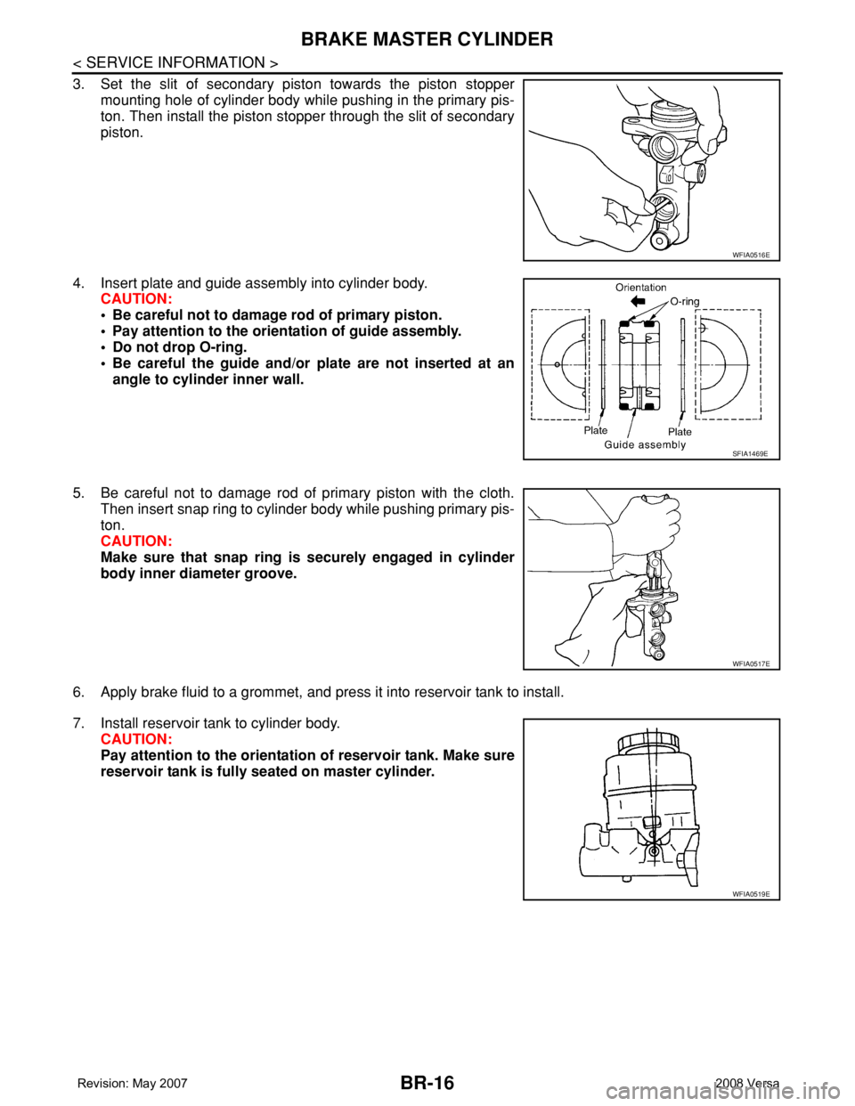
3. Set the slit of secondary piston towards the piston stopper
mounting hole of cylinder body while pushing in the primary pis-
ton. Then install the piston stopper through the slit of secondary
piston.
4. Insert plate and guide assembly into cylinder body.
CAUTION:
• Be careful not to damage rod of primary piston.
• Pay attention to the orientation of guide assembly.
• Do not drop O-ring.
• Be careful the guide and/or plate are not inserted at an
angle to cylinder inner wall.
5. Be careful not to damage rod of primary piston with the cloth.
Then insert snap ring to cylinder body while pushing primary pis-
ton.
CAUTION:
Make sure that snap ring is securely engaged in cylinder
body inner diameter groove.
6. Apply brake fluid to a grommet, and press it into reservoir tank to install.
7. Install reservoir tank to cylinder body.
CAUTION:
Pay attention to the orientation of reservoir tank. Make sure
reservoir tank is fully seated on master cylinder.
WFIA0516E
SFIA1469E
WFIA0517E
WFIA0519E
Page 852 of 2771

CVT FLUID
CVT-13
< SERVICE INFORMATION >
D
E
F
G
H
I
J
K
L
MA
B
CVT
N
O
P
CVT FLUID
Checking CVT FluidINFOID:0000000001703433
FLUID LEVEL CHECK
Fluid level should be checked with the fluid warmed up to 50 to 80°C (122 to 176°F).
1. Check for fluid leakage.
2. With the engine warmed up, drive the vehicle to warm up the
CVT fluid. When ambient temperature is 20°C (68°F), it takes
about 10 minutes for the CVT fluid to warm up to 50 to 80°C
(122 to 176°F).
3. Park the vehicle on a level surface and set the parking brake.
4. With engine at idle, while depressing brake pedal, move the
selector lever throughout the entire shift range and return it to
the “P” position.
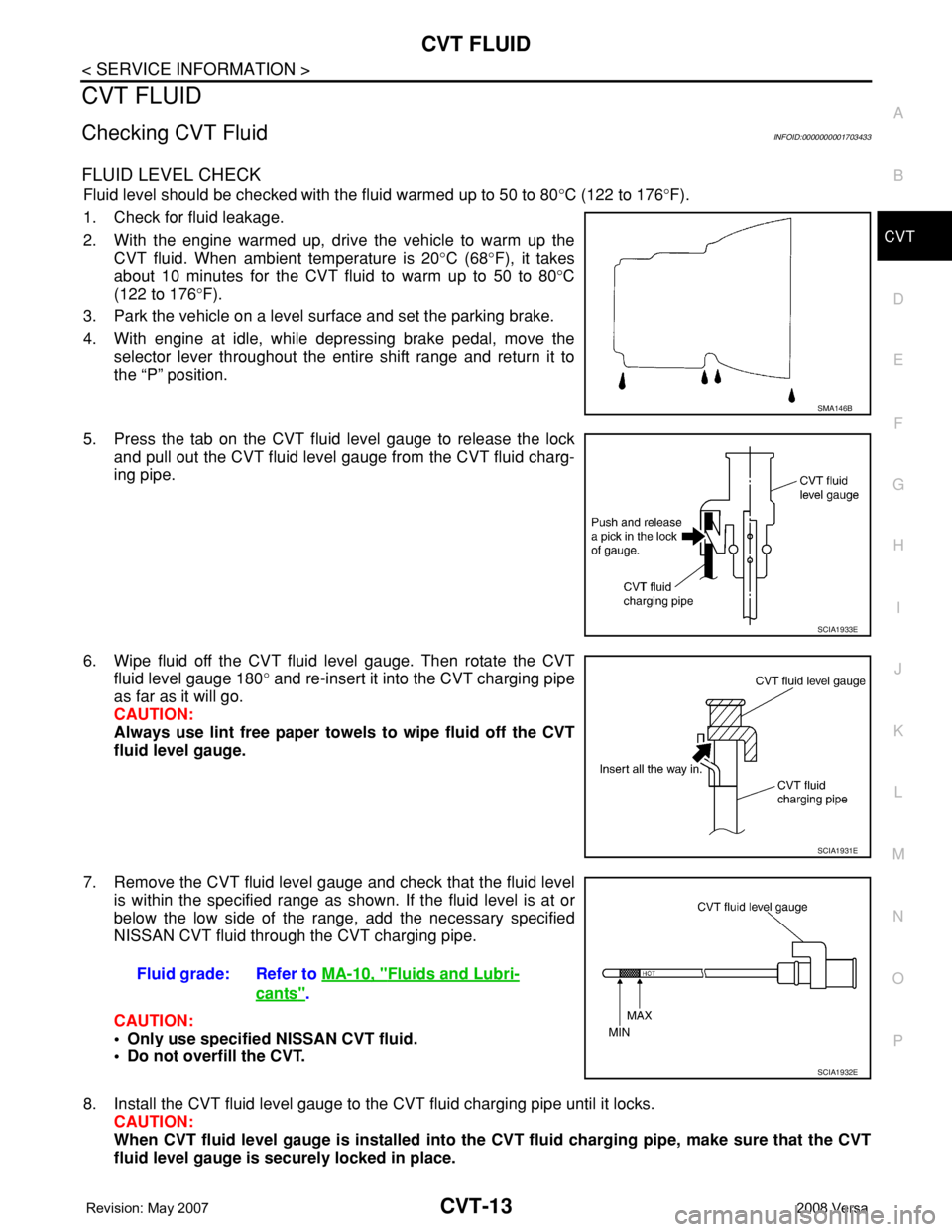
5. Press the tab on the CVT fluid level gauge to release the lock
and pull out the CVT fluid level gauge from the CVT fluid charg-
ing pipe.
6. Wipe fluid off the CVT fluid level gauge. Then rotate the CVT
fluid level gauge 180° and re-insert it into the CVT charging pipe
as far as it will go.
CAUTION:
Always use lint free paper towels to wipe fluid off the CVT
fluid level gauge.
7. Remove the CVT fluid level gauge and check that the fluid level
is within the specified range as shown. If the fluid level is at or
below the low side of the range, add the necessary specified
NISSAN CVT fluid through the CVT charging pipe.
CAUTION:
• Only use specified NISSAN CVT fluid.
• Do not overfill the CVT.
8. Install the CVT fluid level gauge to the CVT fluid charging pipe until it locks.
CAUTION:
When CVT fluid level gauge is installed into the CVT fluid charging pipe, make sure that the CVT
fluid level gauge is securely locked in place.
SMA146B
SCIA1933E
SCIA1931E
Fluid grade: Refer to MA-10, "Fluids and Lubri-
cants".
SCIA1932E
Page 854 of 2771

CVT FLUID
CVT-15
< SERVICE INFORMATION >
D
E
F
G
H
I
J
K
L
MA
B
CVT
N
O
P
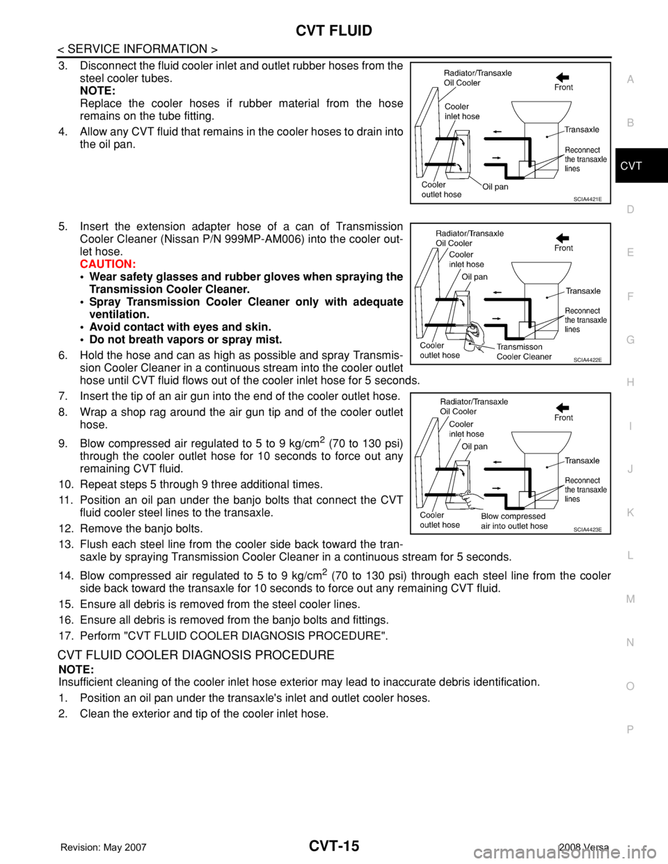
3. Disconnect the fluid cooler inlet and outlet rubber hoses from the
steel cooler tubes.
NOTE:
Replace the cooler hoses if rubber material from the hose
remains on the tube fitting.
4. Allow any CVT fluid that remains in the cooler hoses to drain into
the oil pan.
5. Insert the extension adapter hose of a can of Transmission
Cooler Cleaner (Nissan P/N 999MP-AM006) into the cooler out-
let hose.
CAUTION:
• Wear safety glasses and rubber gloves when spraying the
Transmission Cooler Cleaner.
• Spray Transmission Cooler Cleaner only with adequate
ventilation.
• Avoid contact with eyes and skin.
• Do not breath vapors or spray mist.
6. Hold the hose and can as high as possible and spray Transmis-
sion Cooler Cleaner in a continuous stream into the cooler outlet
hose until CVT fluid flows out of the cooler inlet hose for 5 seconds.
7. Insert the tip of an air gun into the end of the cooler outlet hose.
8. Wrap a shop rag around the air gun tip and of the cooler outlet
hose.
9. Blow compressed air regulated to 5 to 9 kg/cm
2 (70 to 130 psi)
through the cooler outlet hose for 10 seconds to force out any
remaining CVT fluid.
10. Repeat steps 5 through 9 three additional times.
11. Position an oil pan under the banjo bolts that connect the CVT
fluid cooler steel lines to the transaxle.
12. Remove the banjo bolts.
13. Flush each steel line from the cooler side back toward the tran-
saxle by spraying Transmission Cooler Cleaner in a continuous stream for 5 seconds.
14. Blow compressed air regulated to 5 to 9 kg/cm
2 (70 to 130 psi) through each steel line from the cooler
side back toward the transaxle for 10 seconds to force out any remaining CVT fluid.
15. Ensure all debris is removed from the steel cooler lines.
16. Ensure all debris is removed from the banjo bolts and fittings.
17. Perform "CVT FLUID COOLER DIAGNOSIS PROCEDURE".
CVT FLUID COOLER DIAGNOSIS PROCEDURE
NOTE:
Insufficient cleaning of the cooler inlet hose exterior may lead to inaccurate debris identification.
1. Position an oil pan under the transaxle's inlet and outlet cooler hoses.
2. Clean the exterior and tip of the cooler inlet hose.
SCIA4421E
SCIA4422E
SCIA4423E