Page 2631 of 2771
REAR SEAT
SE-23
< SERVICE INFORMATION >
C
D
E
F
G
H
J
K
L
MA
B
SE
N
O
P
NOTE:
Confirm that side hinge bracket location pin is set to the hole on the seatback backside.
Disassembly and AssemblyINFOID:0000000001704271
60:40 SPLIT FOLD DOWN SEAT - SEDAN
Disassembly of Armrest
1. Fold down the armrest and remove the armrest bolt cover (A).
2. Remove the armrest bolt (A).
3. Push the armrest toward left side while pulling backward to
remove.
4. Remove the rear seat bushing, and then remove the armrest
hinge cover by pulling it backward.
Assembly of Armrest
Assembly in the reverse order of disassembly.
WIIA1384E
WIIA1385E
PIIB2915J
PIIB6507E
Page 2636 of 2771

SRS-2
< PRECAUTION >
PRECAUTIONS
PRECAUTION
PRECAUTIONS
Precaution for Supplemental Restraint System (SRS) "AIR BAG" and "SEAT BELT
PRE-TENSIONER"
INFOID:0000000001703904
The Supplemental Restraint System such as “AIR BAG” and “SEAT BELT PRE-TENSIONER”, used along
with a front seat belt, helps to reduce the risk or severity of injury to the driver and front passenger for certain
types of collision. This system includes seat belt switch inputs and dual stage front air bag modules. The SRS
system uses the seat belt switches to determine the front air bag deployment, and may only deploy one front
air bag, depending on the severity of a collision and whether the front occupants are belted or unbelted.
Information necessary to service the system safely is included in the SR and SB section of this Service Man-
ual.
WARNING:
• To avoid rendering the SRS inoperative, which could increase the risk of personal injury or death in
the event of a collision which would result in air bag inflation, all maintenance must be performed by
an authorized NISSAN/INFINITI dealer.
• Improper maintenance, including incorrect removal and installation of the SRS, can lead to personal
injury caused by unintentional activation of the system. For removal of Spiral Cable and Air Bag
Module, see the SR section.
• Do not use electrical test equipment on any circuit related to the SRS unless instructed to in this
Service Manual. SRS wiring harnesses can be identified by yellow and/or orange harnesses or har-
ness connectors.
Precaution for SRS "AIR BAG" and "SEAT BELT PRE-TENSIONER" Service
INFOID:0000000001703905
• Do not use electrical test equipment to check SRS circuits unless instructed to in this Service Manual.
• Before servicing the SRS, turn ignition switch OFF, disconnect both battery cables and wait at least 3 min-
utes.
For approximately 3 minutes after the cables are removed, it is still possible for the air bag and seat belt pre-
tensioner to deploy. Therefore, do not work on any SRS connectors or wires until at least 3 minutes have
passed.
• The air bag diagnosis sensor unit must always be installed with the arrow mark “⇐” pointing toward the front
of the vehicle for proper operation. Also check air bag diagnosis sensor unit for cracks, deformities or rust
before installation and replace as required.
• The spiral cable must be aligned with the neutral position since its rotations are limited. Do not attempt to
turn steering wheel or column after removal of steering gear.
• Handle air bag module carefully. Always place driver and front passenger air bag modules with the pad side
facing upward and seat mounted front side air bag module standing with the stud bolt side facing down.
• Conduct self-diagnosis to check entire SRS for proper function after replacing any components.
• After air bag inflates, the front instrument panel assembly should be replaced if damaged.
• Do not reuse center pillar upper garnish if removed.
Occupant Classification System PrecautionINFOID:0000000001703906
Replace control unit and passenger front seat cushion as an assembly.
Page 2671 of 2771

SPIRAL CABLE
SRS-37
< ON-VEHICLE REPAIR >
C
D
E
F
G
I
J
K
L
MA
B
SRS
N
O
P
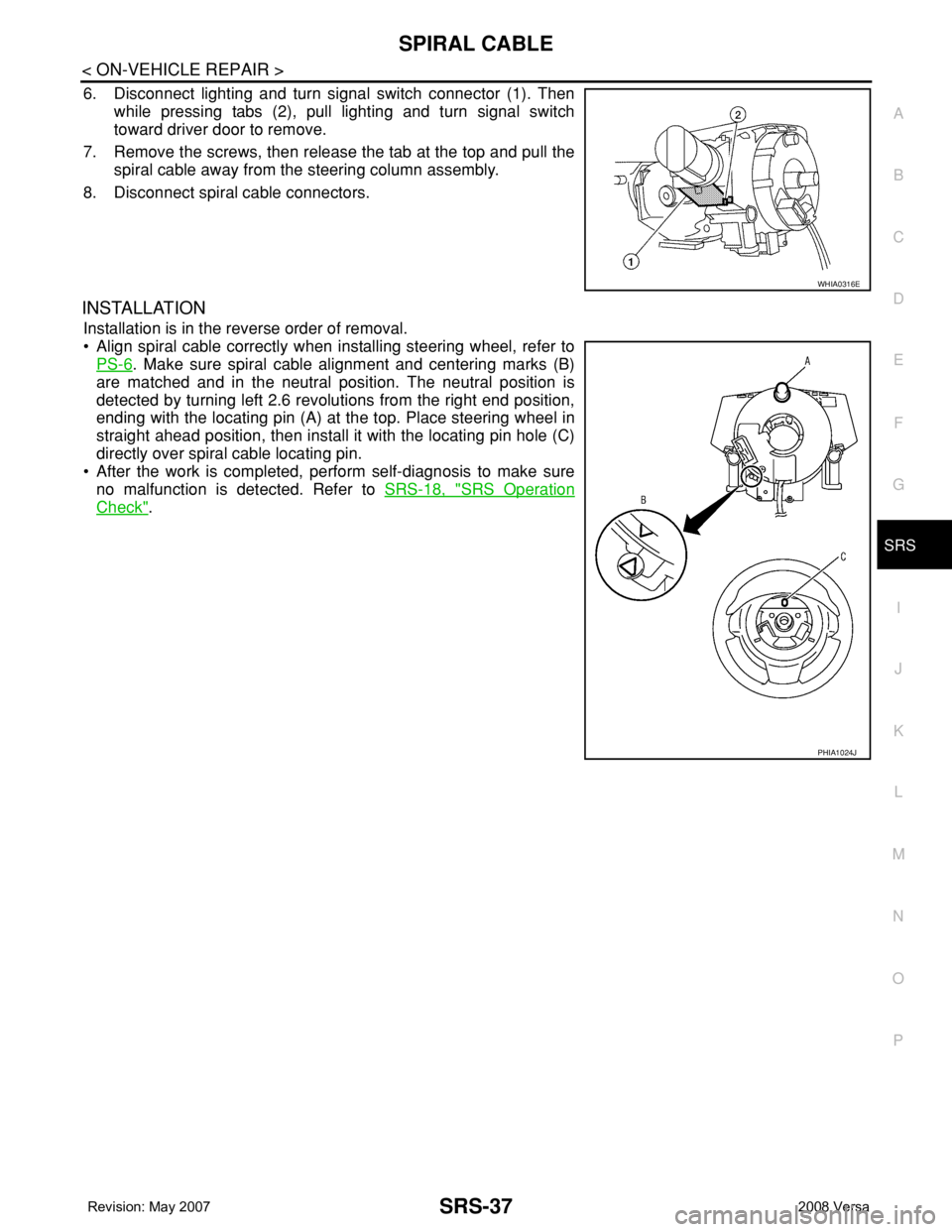
6. Disconnect lighting and turn signal switch connector (1). Then
while pressing tabs (2), pull lighting and turn signal switch
toward driver door to remove.
7. Remove the screws, then release the tab at the top and pull the
spiral cable away from the steering column assembly.
8. Disconnect spiral cable connectors.
INSTALLATION
Installation is in the reverse order of removal.
• Align spiral cable correctly when installing steering wheel, refer to
PS-6
. Make sure spiral cable alignment and centering marks (B)
are matched and in the neutral position. The neutral position is
detected by turning left 2.6 revolutions from the right end position,
ending with the locating pin (A) at the top. Place steering wheel in
straight ahead position, then install it with the locating pin hole (C)
directly over spiral cable locating pin.
• After the work is completed, perform self-diagnosis to make sure
no malfunction is detected. Refer to SRS-18, "
SRS Operation
Check".
WHIA0316E
PHIA1024J
Page 2678 of 2771

SRS-44
< ON-VEHICLE REPAIR >
DIAGNOSIS SENSOR UNIT
DIAGNOSIS SENSOR UNIT
Removal and InstallationINFOID:0000000001703934
REMOVAL
WARNING:
Before disconnecting diagnosis sensor unit harness connector(s), be sure to disconnect harness con-
nectors from air bag modules and front seat belt pre-tensioner to prevent deployment by static elec-
tricity.
CAUTION:
• Before servicing the SRS, turn the ignition switch OFF, disconnect both battery cables and wait at
least 3 minutes.
• Do not disassemble diagnosis sensor unit.
• Do not use old bolts; replace with new bolts.
• Replace the diagnosis sensor unit if it has been dropped or sustained an impact.
• Check diagnosis sensor unit bracket to make sure it is free of deformities, dents, cracks or rust. If it
shows any visible signs of damage, replace with new one.
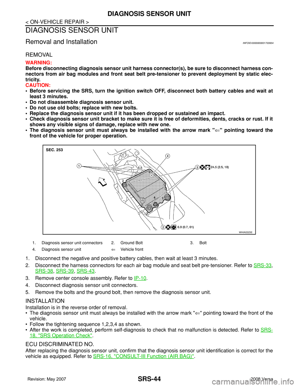
• The diagnosis sensor unit must always be installed with the arrow mark "⇐" pointing toward the
front of the vehicle for proper operation.
1. Disconnect the negative and positive battery cables, then wait at least 3 minutes.
2. Disconnect the harness connectors for each air bag module and seat belt pre-tensioner. Refer to SRS-33
,
SRS-38
, SRS-39, SRS-43.
3. Remove center console assembly. Refer to IP-10
.
4. Disconnect diagnosis sensor unit connectors.
5. Remove the bolts and the ground bolt, then remove the diagnosis sensor unit.
INSTALLATION
Installation is in the reverse order of removal.
• The diagnosis sensor unit must always be installed with the arrow mark "⇐" pointing toward the front of the
vehicle.
• Follow the tightening sequence 1,2,3,4 as shown.
• After the work is completed, perform self-diagnosis to check that no malfunction is detected. Refer to SRS-
18, "SRS Operation Check".
ECU DISCRIMINATED NO.
After replacing the diagnosis sensor unit, confirm that the diagnosis sensor unit identification is correct for the
vehicle as equipped. Refer to SRS-16, "
CONSULT-III Function (AIR BAG)".
1. Diagnosis sensor unit connectors 2. Ground Bolt 3. Bolt
4. Diagnosis sensor unit⇐Vehicle front
WHIA0323E
Page 2755 of 2771

WW-22
< SERVICE INFORMATION >
FRONT WIPER AND WASHER SYSTEM
Removal and Installation of Front Wiper and Washer Switch
INFOID:0000000001704561
REMOVAL
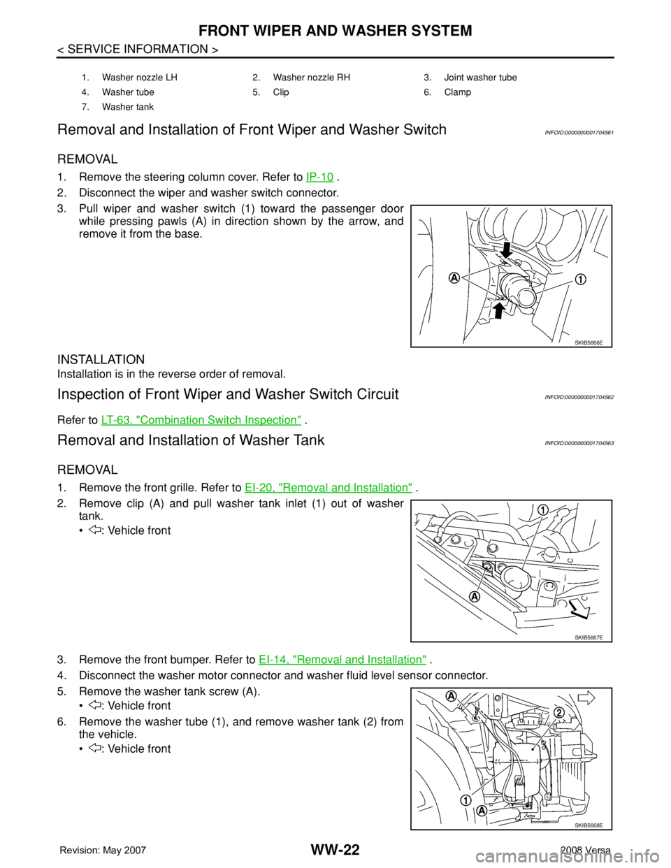
1. Remove the steering column cover. Refer to IP-10 .
2. Disconnect the wiper and washer switch connector.
3. Pull wiper and washer switch (1) toward the passenger door
while pressing pawls (A) in direction shown by the arrow, and
remove it from the base.
INSTALLATION
Installation is in the reverse order of removal.
Inspection of Front Wiper and Washer Switch CircuitINFOID:0000000001704562
Refer to LT-63, "Combination Switch Inspection" .
Removal and Installation of Washer TankINFOID:0000000001704563
REMOVAL
1. Remove the front grille. Refer to EI-20, "Removal and Installation" .
2. Remove clip (A) and pull washer tank inlet (1) out of washer
tank.
• : Vehicle front
3. Remove the front bumper. Refer to EI-14, "
Removal and Installation" .
4. Disconnect the washer motor connector and washer fluid level sensor connector.
5. Remove the washer tank screw (A).
• : Vehicle front
6. Remove the washer tube (1), and remove washer tank (2) from
the vehicle.
• : Vehicle front
1. Washer nozzle LH 2. Washer nozzle RH 3. Joint washer tube
4. Washer tube 5. Clip 6. Clamp
7. Washer tank
SKIB5666E
SKIB5667E
SKIB5668E
Page 2766 of 2771
REAR WIPER AND WASHER SYSTEM
WW-33
< SERVICE INFORMATION >
C
D
E
F
G
H
I
J
L
MA
B
WW
N
O
P
5. Disconnect the rear wiper motor connector (B).
6. Remove the bolts (A) and remove the rear wiper motor (1).
Installation
Installation is in the reverse order of removal.
CAUTION:
Do not drop the wiper motor or cause it to contact other parts.
REAR WASHER TUBE LAYOUT
NOTE:
Connect the check valve (2) to the washer fluid tube (1) so that the
directional arrow on the check valve (2) points towards the washer
nozzle tube (3).
REAR WASHER NOZZLE
Removal
1. Remove the back door window garnish. Refer to EI-36, "Removal and Installation" .
2. Disconnect rear washer tube from rear washer nozzle.
LKIA0789E
1 Washer fluid reservoir 2 Washer fluid tube to rear door 3 Rear washer nozzle
4Check valve
LKIA0790E
WKIA4242E