2008 NISSAN LATIO turn signal
[x] Cancel search: turn signalPage 1479 of 2771
DTC P0850 PNP SWITCH
EC-405
< SERVICE INFORMATION >
C
D
E
F
G
H
I
J
K
L
MA
EC
N
P O
DTC P0850 PNP SWITCH
Component DescriptionINFOID:0000000001702921
When the shift lever position is P or N (A/T, CVT), Neutral (M/T), park/neutral position (PNP) switch is ON.
ECM detects the position because the continuity of the line (the ON signal) exists.
CONSULT-II Reference Value in Data Monitor ModeINFOID:0000000001702922
Specification data are reference values.
On Board Diagnosis LogicINFOID:0000000001702923
DTC Confirmation ProcedureINFOID:0000000001702924
CAUTION:
Always drive vehicle at a safe speed.
NOTE:
If DTC Confirmation Procedure has been previously conducted, always turn ignition switch OFF and wait at
least 10 seconds before conducting the next test.
WITH CONSULT-II
1. Turn ignition switch ON.
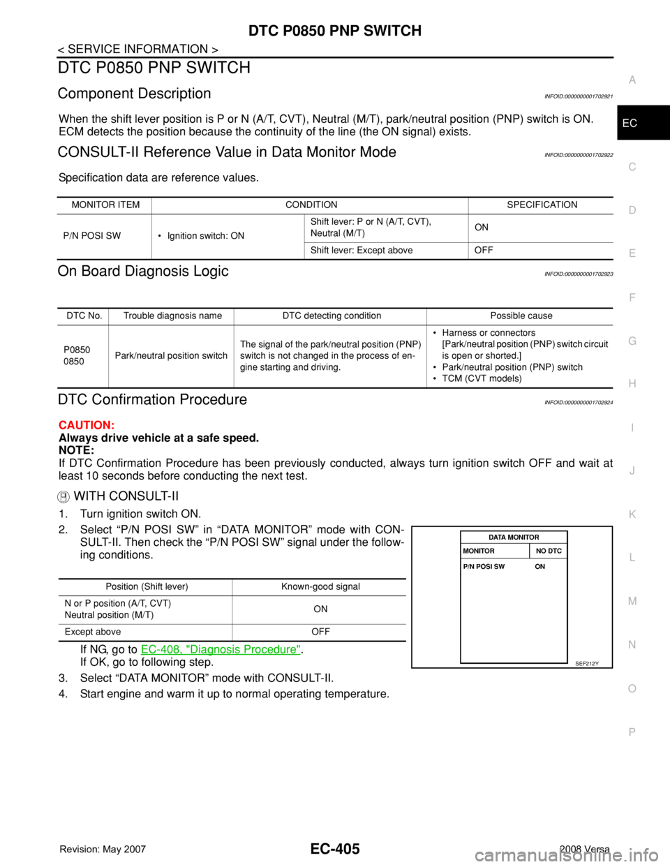
2. Select “P/N POSI SW” in “DATA MONITOR” mode with CON-
SULT-II. Then check the “P/N POSI SW” signal under the follow-
ing conditions.
If NG, go to EC-408, "
Diagnosis Procedure".
If OK, go to following step.
3. Select “DATA MONITOR” mode with CONSULT-II.
4. Start engine and warm it up to normal operating temperature.
MONITOR ITEM CONDITION SPECIFICATION
P/N POSI SW • Ignition switch: ONShift lever: P or N (A/T, CVT),
Neutral (M/T)ON
Shift lever: Except above OFF
DTC No. Trouble diagnosis name DTC detecting condition Possible cause
P0850
0850Park/neutral position switchThe signal of the park/neutral position (PNP)
switch is not changed in the process of en-
gine starting and driving.• Harness or connectors
[Park/neutral position (PNP) switch circuit
is open or shorted.]
• Park/neutral position (PNP) switch
• TCM (CVT models)
Position (Shift lever) Known-good signal
N or P position (A/T, CVT)
Neutral position (M/T)ON
Except above OFF
SEF212Y
Page 1480 of 2771
EC-406
< SERVICE INFORMATION >
DTC P0850 PNP SWITCH
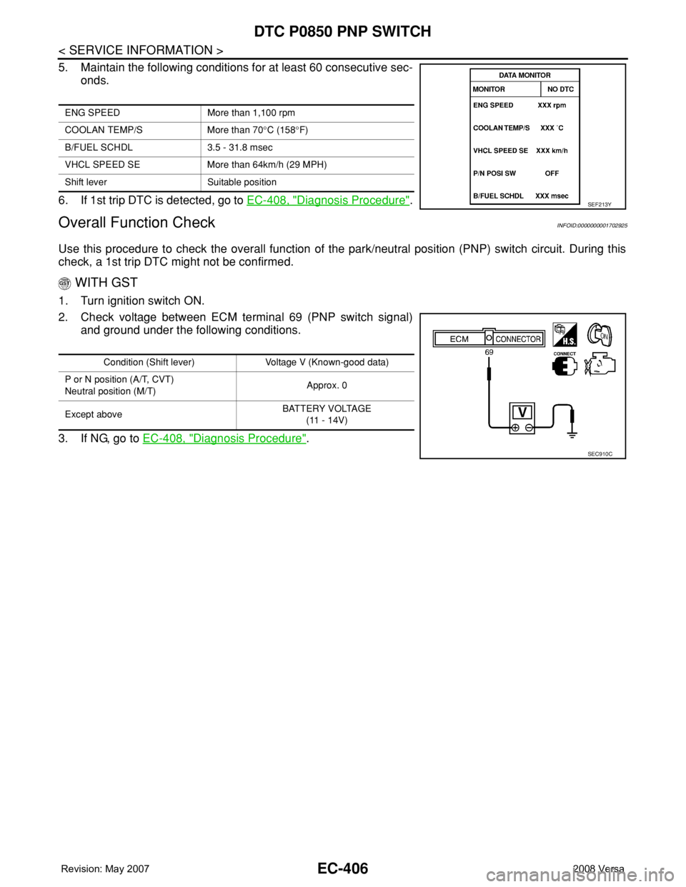
5. Maintain the following conditions for at least 60 consecutive sec-
onds.
6. If 1st trip DTC is detected, go to EC-408, "
Diagnosis Procedure".
Overall Function CheckINFOID:0000000001702925
Use this procedure to check the overall function of the park/neutral position (PNP) switch circuit. During this
check, a 1st trip DTC might not be confirmed.
WITH GST
1. Turn ignition switch ON.
2. Check voltage between ECM terminal 69 (PNP switch signal)
and ground under the following conditions.
3. If NG, go to EC-408, "
Diagnosis Procedure".
ENG SPEED More than 1,100 rpm
COOLAN TEMP/S More than 70°C (158°F)
B/FUEL SCHDL 3.5 - 31.8 msec
VHCL SPEED SE More than 64km/h (29 MPH)
Shift lever Suitable position
SEF213Y
Condition (Shift lever) Voltage V (Known-good data)
P or N position (A/T, CVT)
Neutral position (M/T)Approx. 0
Except aboveBATTERY VOLTAGE
(11 - 14V)
SEC910C
Page 1482 of 2771
EC-408
< SERVICE INFORMATION >
DTC P0850 PNP SWITCH
Diagnosis Procedure
INFOID:0000000001702927
A/T MODELS
1.CHECK PNP SWITCH POWER SUPPLY CIRCUIT
1. Turn ignition switch OFF.
2. Disconnect PNP switch harness connector.
3. Turn ignition switch ON.
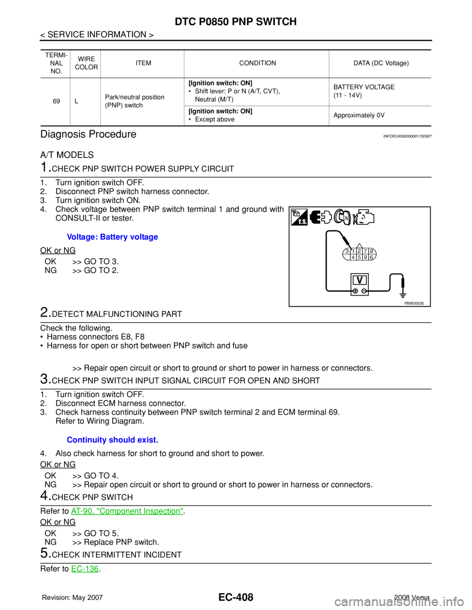
4. Check voltage between PNP switch terminal 1 and ground with
CONSULT-II or tester.
OK or NG
OK >> GO TO 3.
NG >> GO TO 2.
2.DETECT MALFUNCTIONING PART
Check the following.
• Harness connectors E8, F8
• Harness for open or short between PNP switch and fuse
>> Repair open circuit or short to ground or short to power in harness or connectors.
3.CHECK PNP SWITCH INPUT SIGNAL CIRCUIT FOR OPEN AND SHORT
1. Turn ignition switch OFF.
2. Disconnect ECM harness connector.
3. Check harness continuity between PNP switch terminal 2 and ECM terminal 69.
Refer to Wiring Diagram.
4. Also check harness for short to ground and short to power.
OK or NG
OK >> GO TO 4.
NG >> Repair open circuit or short to ground or short to power in harness or connectors.
4.CHECK PNP SWITCH
Refer to AT-90, "
Component Inspection".
OK or NG
OK >> GO TO 5.
NG >> Replace PNP switch.
5.CHECK INTERMITTENT INCIDENT
Refer to EC-136
.
TERMI-
NAL
NO.WIRE
COLORITEM CONDITION DATA (DC Voltage)
69 LPark/neutral position
(PNP) switch[Ignition switch: ON]
• Shift lever: P or N (A/T, CVT),
Neutral (M/T)BATTERY VOLTAGE
(11 - 14V)
[Ignition switch: ON]
• Except aboveApproximately 0V
Voltage: Battery voltage
PBIB3002E
Continuity should exist.
Page 1483 of 2771
DTC P0850 PNP SWITCH
EC-409
< SERVICE INFORMATION >
C
D
E
F
G
H
I
J
K
L
MA
EC
N
P O
>>INSPECTION END
M/T MODELS
1.CHECK PNP SWITCH POWER SUPPLY CIRCUIT
1. Turn ignition switch OFF.
2. Disconnect PNP switch harness connector.
3. Turn ignition switch ON.
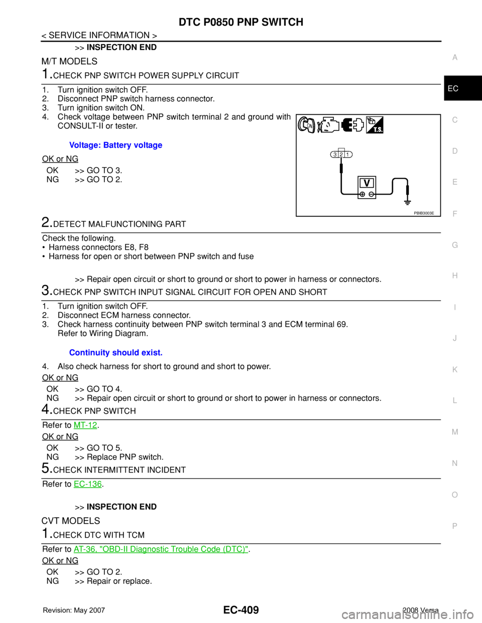
4. Check voltage between PNP switch terminal 2 and ground with
CONSULT-II or tester.
OK or NG
OK >> GO TO 3.
NG >> GO TO 2.
2.DETECT MALFUNCTIONING PART
Check the following.
• Harness connectors E8, F8
• Harness for open or short between PNP switch and fuse
>> Repair open circuit or short to ground or short to power in harness or connectors.
3.CHECK PNP SWITCH INPUT SIGNAL CIRCUIT FOR OPEN AND SHORT
1. Turn ignition switch OFF.
2. Disconnect ECM harness connector.
3. Check harness continuity between PNP switch terminal 3 and ECM terminal 69.
Refer to Wiring Diagram.
4. Also check harness for short to ground and short to power.
OK or NG
OK >> GO TO 4.
NG >> Repair open circuit or short to ground or short to power in harness or connectors.
4.CHECK PNP SWITCH
Refer to MT-12
.
OK or NG
OK >> GO TO 5.
NG >> Replace PNP switch.
5.CHECK INTERMITTENT INCIDENT
Refer to EC-136
.
>>INSPECTION END
CVT MODELS
1.CHECK DTC WITH TCM
Refer to AT-36, "
OBD-II Diagnostic Trouble Code (DTC)".
OK or NG
OK >> GO TO 2.
NG >> Repair or replace.Voltage: Battery voltage
PBIB3003E
Continuity should exist.
Page 1484 of 2771

EC-410
< SERVICE INFORMATION >
DTC P0850 PNP SWITCH
2.CHECK STARTING SYSTEM
Turn ignition switch OFF, then turn it to START.
Does starter motor operate?
Ye s o r N o
Ye s > > G O T O 3 .
No >> Refer to SC-8
.
3.CHECK PNP SWITCH INPUT SIGNAL CIRCUIT FOR OPEN AND SHORT-I
1. Turn ignition switch OFF.
2. Disconnect ECM and TCM harness connectors.
3. Check harness continuity between TCM terminal 24 and ECM terminal 69.
Refer to Wiring Diagram.
4. Also check harness for short to ground and short to power.
OK or NG
OK >> GO TO 5.
NG >> GO TO 4.
4.DETECT MALFUNCTIONING PART
Check the following.
• Harness connectors F8, E8
• Harness for open or short between TCM and ECM.
>> Repair open circuit or short to ground or short to power in harness or connectors.
5.CHECK INTERMITTENT INCIDENT
Refer to EC-136
.
>>INSPECTION END Continuity should exist.
Page 1500 of 2771
EC-426
< SERVICE INFORMATION >
DTC P1225 TP SENSOR
DTC P1225 TP SENSOR
Component DescriptionINFOID:0000000001702937
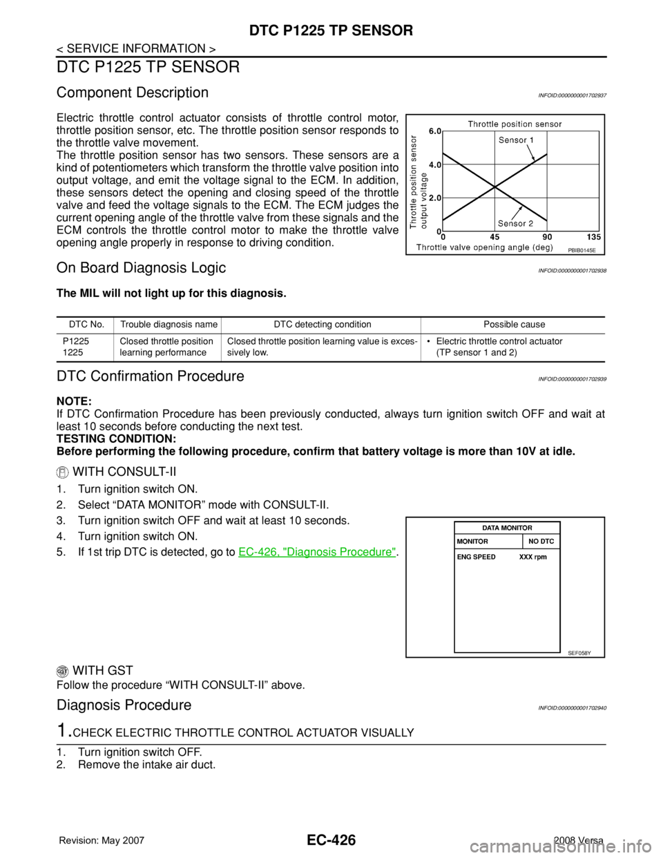
Electric throttle control actuator consists of throttle control motor,
throttle position sensor, etc. The throttle position sensor responds to
the throttle valve movement.
The throttle position sensor has two sensors. These sensors are a
kind of potentiometers which transform the throttle valve position into
output voltage, and emit the voltage signal to the ECM. In addition,
these sensors detect the opening and closing speed of the throttle
valve and feed the voltage signals to the ECM. The ECM judges the
current opening angle of the throttle valve from these signals and the
ECM controls the throttle control motor to make the throttle valve
opening angle properly in response to driving condition.
On Board Diagnosis LogicINFOID:0000000001702938
The MIL will not light up for this diagnosis.
DTC Confirmation ProcedureINFOID:0000000001702939
NOTE:
If DTC Confirmation Procedure has been previously conducted, always turn ignition switch OFF and wait at
least 10 seconds before conducting the next test.
TESTING CONDITION:
Before performing the following procedure, confirm that battery voltage is more than 10V at idle.
WITH CONSULT-II
1. Turn ignition switch ON.
2. Select “DATA MONITOR” mode with CONSULT-II.
3. Turn ignition switch OFF and wait at least 10 seconds.
4. Turn ignition switch ON.
5. If 1st trip DTC is detected, go to EC-426, "
Diagnosis Procedure".
WITH GST
Follow the procedure “WITH CONSULT-II” above.
Diagnosis ProcedureINFOID:0000000001702940
1.CHECK ELECTRIC THROTTLE CONTROL ACTUATOR VISUALLY
1. Turn ignition switch OFF.
2. Remove the intake air duct.
PBIB0145E
DTC No. Trouble diagnosis name DTC detecting condition Possible cause
P1225
1225Closed throttle position
learning performanceClosed throttle position learning value is exces-
sively low.• Electric throttle control actuator
(TP sensor 1 and 2)
SEF058Y
Page 1502 of 2771
EC-428
< SERVICE INFORMATION >
DTC P1226 TP SENSOR
DTC P1226 TP SENSOR
Component DescriptionINFOID:0000000001702942
Electric throttle control actuator consists of throttle control motor,
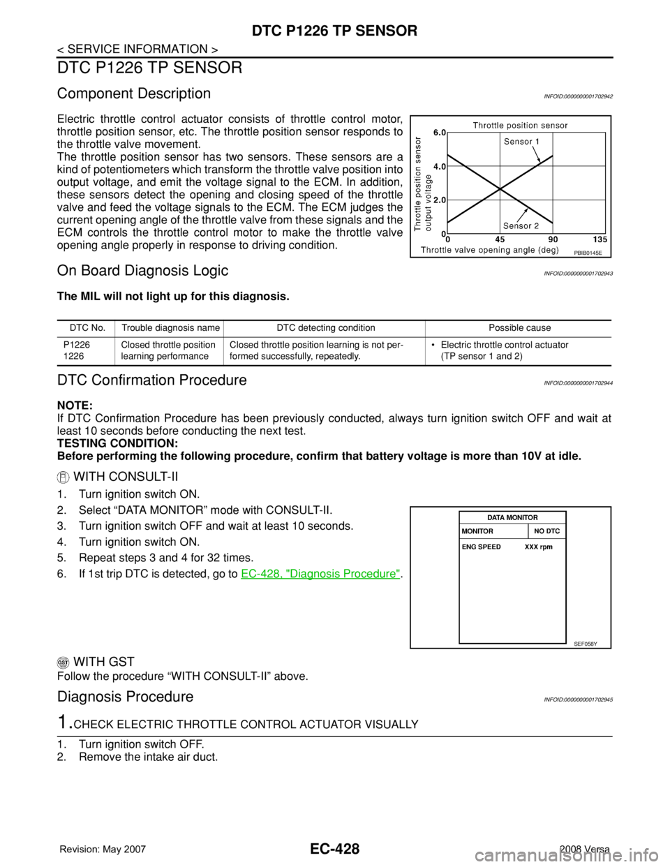
throttle position sensor, etc. The throttle position sensor responds to
the throttle valve movement.
The throttle position sensor has two sensors. These sensors are a
kind of potentiometers which transform the throttle valve position into
output voltage, and emit the voltage signal to the ECM. In addition,
these sensors detect the opening and closing speed of the throttle
valve and feed the voltage signals to the ECM. The ECM judges the
current opening angle of the throttle valve from these signals and the
ECM controls the throttle control motor to make the throttle valve
opening angle properly in response to driving condition.
On Board Diagnosis LogicINFOID:0000000001702943
The MIL will not light up for this diagnosis.
DTC Confirmation ProcedureINFOID:0000000001702944
NOTE:
If DTC Confirmation Procedure has been previously conducted, always turn ignition switch OFF and wait at
least 10 seconds before conducting the next test.
TESTING CONDITION:
Before performing the following procedure, confirm that battery voltage is more than 10V at idle.
WITH CONSULT-II
1. Turn ignition switch ON.
2. Select “DATA MONITOR” mode with CONSULT-II.
3. Turn ignition switch OFF and wait at least 10 seconds.
4. Turn ignition switch ON.
5. Repeat steps 3 and 4 for 32 times.
6. If 1st trip DTC is detected, go to EC-428, "
Diagnosis Procedure".
WITH GST
Follow the procedure “WITH CONSULT-II” above.
Diagnosis ProcedureINFOID:0000000001702945
1.CHECK ELECTRIC THROTTLE CONTROL ACTUATOR VISUALLY
1. Turn ignition switch OFF.
2. Remove the intake air duct.
PBIB0145E
DTC No. Trouble diagnosis name DTC detecting condition Possible cause
P1226
1226Closed throttle position
learning performanceClosed throttle position learning is not per-
formed successfully, repeatedly.• Electric throttle control actuator
(TP sensor 1 and 2)
SEF058Y
Page 1510 of 2771
EC-436
< SERVICE INFORMATION >
DTC P1564 ASCD STEERING SWITCH
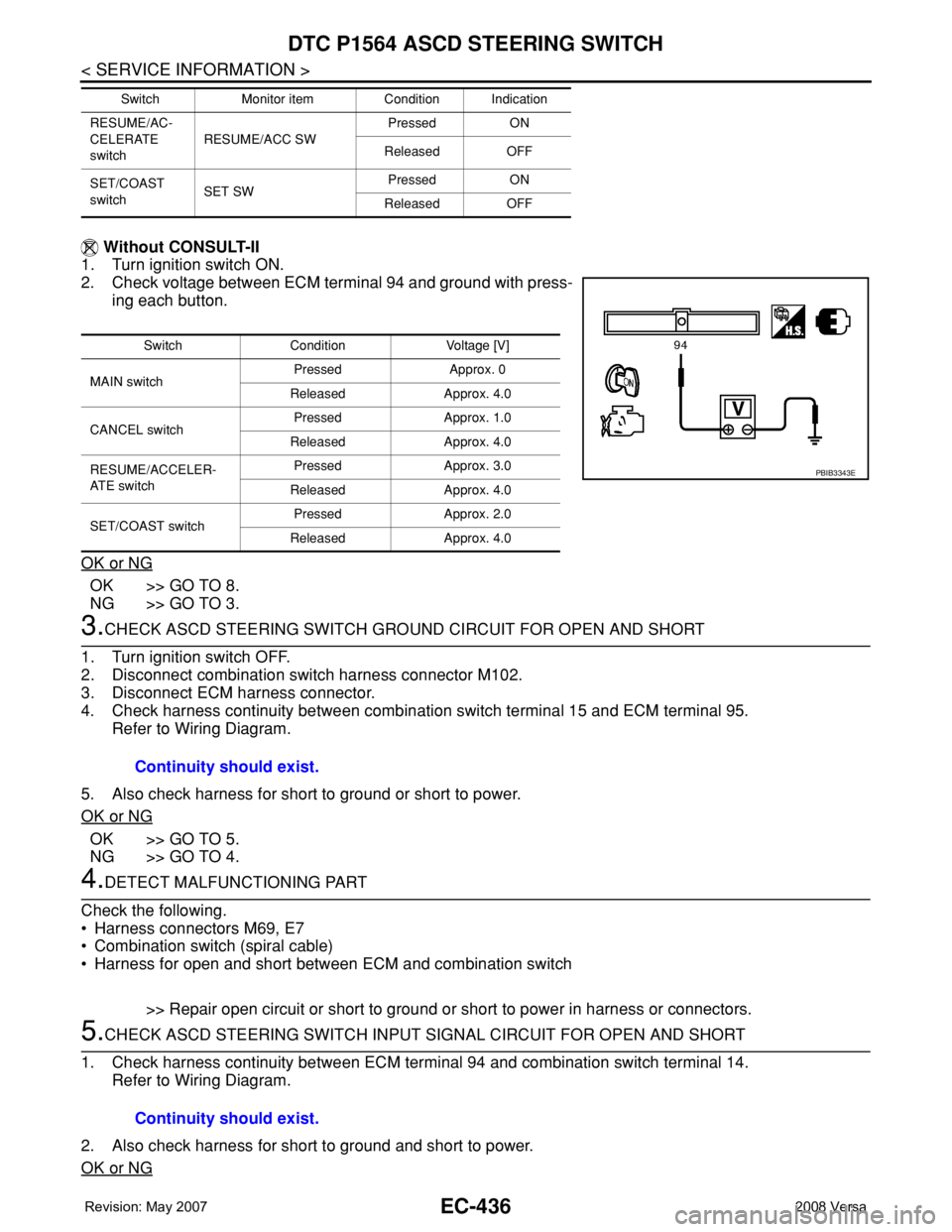
Without CONSULT-II
1. Turn ignition switch ON.
2. Check voltage between ECM terminal 94 and ground with press-
ing each button.
OK or NG
OK >> GO TO 8.
NG >> GO TO 3.
3.CHECK ASCD STEERING SWITCH GROUND CIRCUIT FOR OPEN AND SHORT
1. Turn ignition switch OFF.
2. Disconnect combination switch harness connector M102.
3. Disconnect ECM harness connector.
4. Check harness continuity between combination switch terminal 15 and ECM terminal 95.
Refer to Wiring Diagram.
5. Also check harness for short to ground or short to power.
OK or NG
OK >> GO TO 5.
NG >> GO TO 4.
4.DETECT MALFUNCTIONING PART
Check the following.
• Harness connectors M69, E7
• Combination switch (spiral cable)
• Harness for open and short between ECM and combination switch
>> Repair open circuit or short to ground or short to power in harness or connectors.
5.CHECK ASCD STEERING SWITCH INPUT SIGNAL CIRCUIT FOR OPEN AND SHORT
1. Check harness continuity between ECM terminal 94 and combination switch terminal 14.
Refer to Wiring Diagram.
2. Also check harness for short to ground and short to power.
OK or NG
RESUME/AC-
CELERATE
switchRESUME/ACC SWPressed ON
Released OFF
SET/COAST
switchSET SWPressed ON
Released OFF Switch Monitor item Condition Indication
Switch Condition Voltage [V]
MAIN switchPressed Approx. 0
Released Approx. 4.0
CANCEL switchPressed Approx. 1.0
Released Approx. 4.0
RESUME/ACCELER-
AT E s w i t c hPressed Approx. 3.0
Released Approx. 4.0
SET/COAST switchPressed Approx. 2.0
Released Approx. 4.0
PBIB3343E
Continuity should exist.
Continuity should exist.