2008 NISSAN LATIO turn signal
[x] Cancel search: turn signalPage 1552 of 2771
EC-478
< SERVICE INFORMATION >
DTC P2122, P2123 APP SENSOR
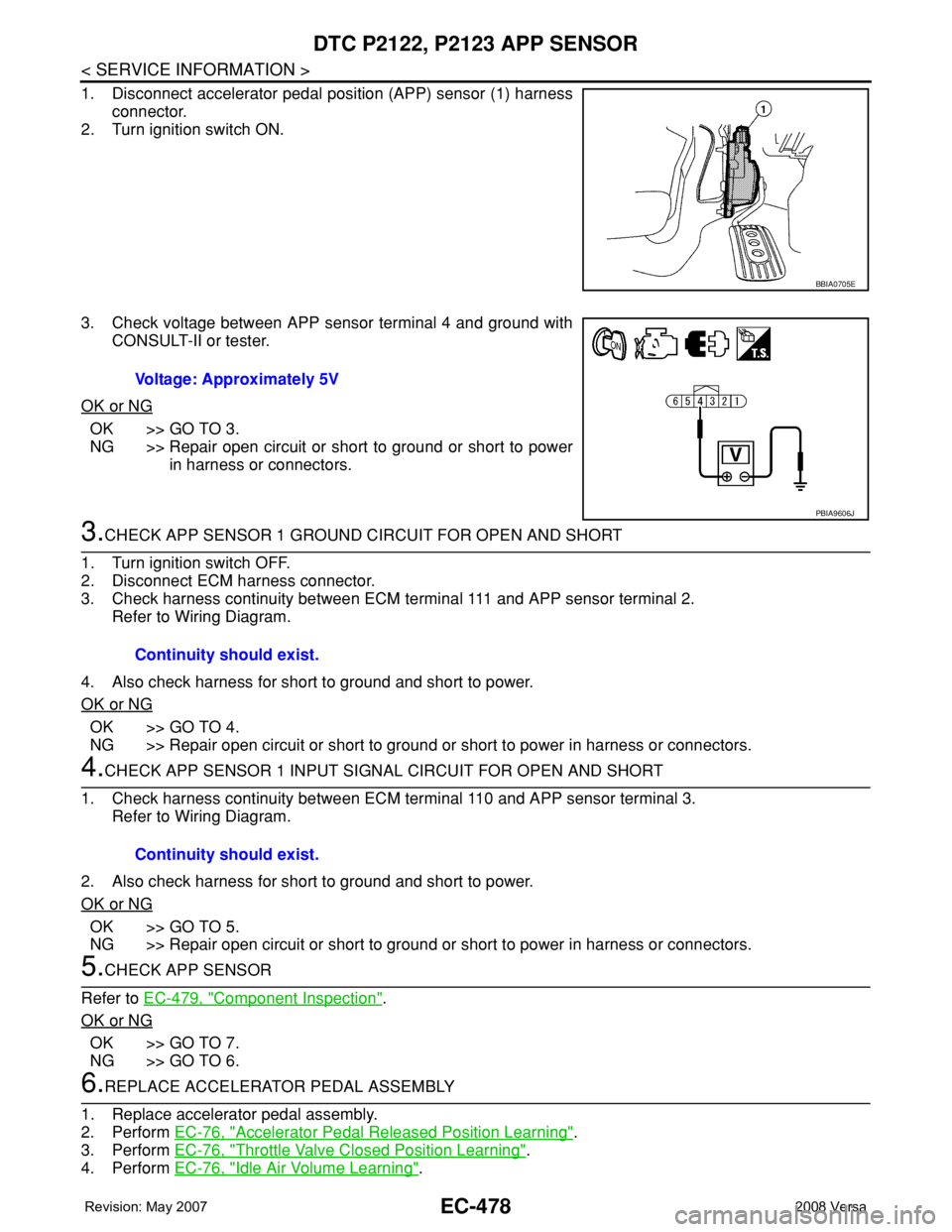
1. Disconnect accelerator pedal position (APP) sensor (1) harness
connector.
2. Turn ignition switch ON.
3. Check voltage between APP sensor terminal 4 and ground with
CONSULT-II or tester.
OK or NG
OK >> GO TO 3.
NG >> Repair open circuit or short to ground or short to power
in harness or connectors.
3.CHECK APP SENSOR 1 GROUND CIRCUIT FOR OPEN AND SHORT
1. Turn ignition switch OFF.
2. Disconnect ECM harness connector.
3. Check harness continuity between ECM terminal 111 and APP sensor terminal 2.
Refer to Wiring Diagram.
4. Also check harness for short to ground and short to power.
OK or NG
OK >> GO TO 4.
NG >> Repair open circuit or short to ground or short to power in harness or connectors.
4.CHECK APP SENSOR 1 INPUT SIGNAL CIRCUIT FOR OPEN AND SHORT
1. Check harness continuity between ECM terminal 110 and APP sensor terminal 3.
Refer to Wiring Diagram.
2. Also check harness for short to ground and short to power.
OK or NG
OK >> GO TO 5.
NG >> Repair open circuit or short to ground or short to power in harness or connectors.
5.CHECK APP SENSOR
Refer to EC-479, "
Component Inspection".
OK or NG
OK >> GO TO 7.
NG >> GO TO 6.
6.REPLACE ACCELERATOR PEDAL ASSEMBLY
1. Replace accelerator pedal assembly.
2. Perform EC-76, "
Accelerator Pedal Released Position Learning".
3. Perform EC-76, "
Throttle Valve Closed Position Learning".
4. Perform EC-76, "
Idle Air Volume Learning".
BBIA0705E
Voltage: Approximately 5V
PBIA9606J
Continuity should exist.
Continuity should exist.
Page 1553 of 2771
DTC P2122, P2123 APP SENSOR
EC-479
< SERVICE INFORMATION >
C
D
E
F
G
H
I
J
K
L
MA
EC
N
P O
>>INSPECTION END
7.CHECK INTERMITTENT INCIDENT
Refer to EC-136
.
>>INSPECTION END
Component InspectionINFOID:0000000001703015
ACCELERATOR PEDAL POSITION SENSOR
1. Reconnect all harness connectors disconnected.
2. Turn ignition switch ON.
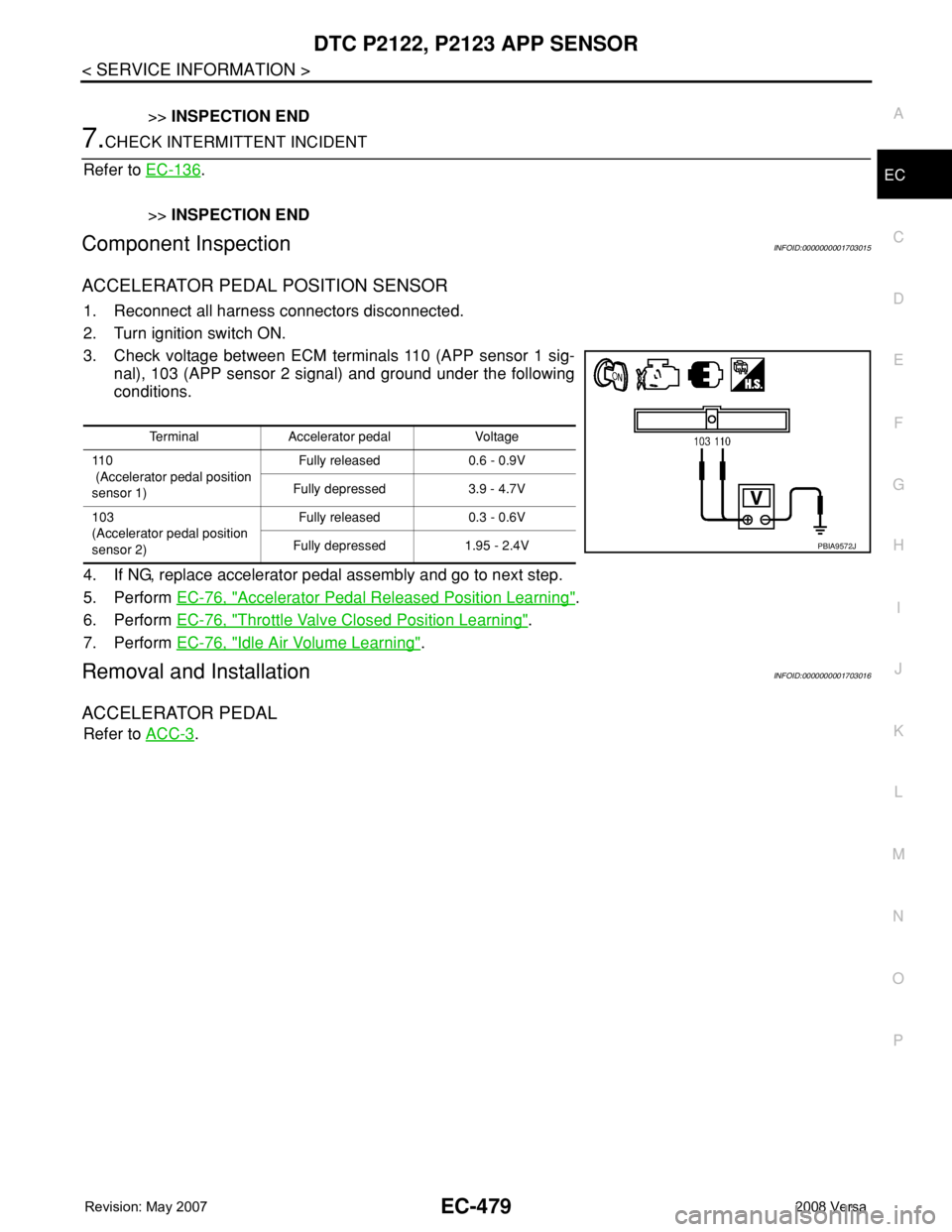
3. Check voltage between ECM terminals 110 (APP sensor 1 sig-
nal), 103 (APP sensor 2 signal) and ground under the following
conditions.
4. If NG, replace accelerator pedal assembly and go to next step.
5. Perform EC-76, "
Accelerator Pedal Released Position Learning".
6. Perform EC-76, "
Throttle Valve Closed Position Learning".
7. Perform EC-76, "
Idle Air Volume Learning".
Removal and InstallationINFOID:0000000001703016
ACCELERATOR PEDAL
Refer to ACC-3.
Terminal Accelerator pedal Voltage
11 0
(Accelerator pedal position
sensor 1)Fully released 0.6 - 0.9V
Fully depressed 3.9 - 4.7V
103
(Accelerator pedal position
sensor 2)Fully released 0.3 - 0.6V
Fully depressed 1.95 - 2.4V
PBIA9572J
Page 1559 of 2771
DTC P2127, P2128 APP SENSOR
EC-485
< SERVICE INFORMATION >
C
D
E
F
G
H
I
J
K
L
MA
EC
N
P O
• Refrigerant pressure sensor (Refer to MTC-22.)
OK or NG
OK >> GO TO 10.
NG >> Replace malfunctioning component.
6.CHECK APP SENSOR 2 GROUND CIRCUIT FOR OPEN AND SHORT
1. Turn ignition switch OFF.
2. Disconnect ECM harness connector.
3. Check harness continuity between ECM terminal 104 and APP sensor terminal 1.
Refer to Wiring Diagram.
4. Also check harness for short to ground and short to power.
OK or NG
OK >> GO TO 7.
NG >> Repair open circuit or short to ground or short to power in harness or connectors.
7.CHECK APP SENSOR 2 INPUT SIGNAL CIRCUIT FOR OPEN AND SHORT
1. Check harness continuity between ECM terminal 103 and APP sensor terminal 6.
Refer to Wiring Diagram.
2. Also check harness for short to ground and short to power.
OK or NG
OK >> GO TO 8.
NG >> Repair open circuit or short to ground or short to power in harness or connectors.
8.CHECK APP SENSOR
Refer to EC-485, "
Component Inspection".
OK or NG
OK >> GO TO 10.
NG >> GO TO 9.
9.REPLACE ACCELERATOR PEDAL ASSEMBLY
1. Replace accelerator pedal assembly.
2. Perform EC-76, "
Accelerator Pedal Released Position Learning".
3. Perform EC-76, "
Throttle Valve Closed Position Learning".
4. Perform EC-76, "
Idle Air Volume Learning".
>>INSPECTION END
10.CHECK INTERMITTENT INCIDENT
Refer to EC-136
.
>>INSPECTION END
Component InspectionINFOID:0000000001703023
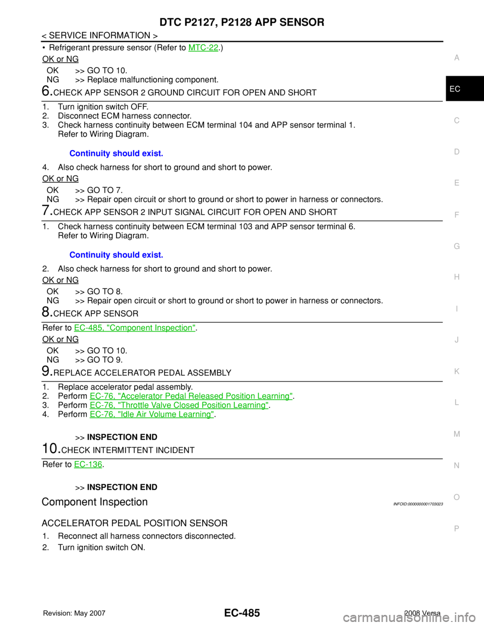
ACCELERATOR PEDAL POSITION SENSOR
1. Reconnect all harness connectors disconnected.
2. Turn ignition switch ON.Continuity should exist.
Continuity should exist.
Page 1561 of 2771
DTC P2135 TP SENSOR
EC-487
< SERVICE INFORMATION >
C
D
E
F
G
H
I
J
K
L
MA
EC
N
P O
DTC P2135 TP SENSOR
Component DescriptionINFOID:0000000001703025
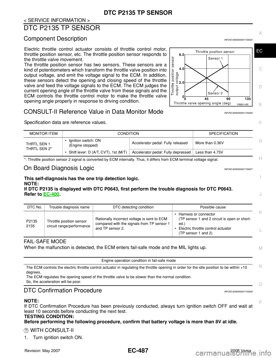
Electric throttle control actuator consists of throttle control motor,
throttle position sensor, etc. The throttle position sensor responds to
the throttle valve movement.
The throttle position sensor has two sensors. These sensors are a
kind of potentiometers which transform the throttle valve position into
output voltage, and emit the voltage signal to the ECM. In addition,
these sensors detect the opening and closing speed of the throttle
valve and feed the voltage signals to the ECM. The ECM judges the
current opening angle of the throttle valve from these signals and the
ECM controls the throttle control motor to make the throttle valve
opening angle properly in response to driving condition.
CONSULT-II Reference Value in Data Monitor ModeINFOID:0000000001703026
Specification data are reference values.
*: Throttle position sensor 2 signal is converted by ECM internally. Thus, it differs from ECM terminal voltage signal.
On Board Diagnosis LogicINFOID:0000000001703027
This self-diagnosis has the one trip detection logic.
NOTE:
If DTC P2135 is displayed with DTC P0643, first perform the trouble diagnosis for DTC P0643.
Refer to EC-400
.
FAIL-SAFE MODE
When the malfunction is detected, the ECM enters fail-safe mode and the MIL lights up.
DTC Confirmation ProcedureINFOID:0000000001703028
NOTE:
If DTC Confirmation Procedure has been previously conducted, always turn ignition switch OFF and wait at
least 10 seconds before conducting the next test.
TESTING CONDITION:
Before performing the following procedure, confirm that battery voltage is more than 8V at idle.
WITH CONSULT-II
1. Turn ignition switch ON.
PBIB0145E
MONITOR ITEM CONDITION SPECIFICATION
THRTL SEN 1
THRTL SEN 2*• Ignition switch: ON
(Engine stopped)Accelerator pedal: Fully released More than 0.36V
• Shift lever: D (A/T, CVT), 1st (M/T) Accelerator pedal: Fully depressed Less than 4.75V
DTC No. Trouble diagnosis name DTC detecting condition Possible cause
P2135
2135Throttle position sensor
circuit range/performanceRationally incorrect voltage is sent to ECM
compared with the signals from TP sensor 1
and TP sensor 2.• Harness or connector
(TP sensor 1 and 2 circuit is open or short-
ed.)
• Electric throttle control actuator
(TP sensor 1 and 2)
Engine operation condition in fail-safe mode
The ECM controls the electric throttle control actuator in regulating the throttle opening in order for the idle position to be within +10
degrees.
The ECM regulates the opening speed of the throttle valve to be slower than the normal condition.
So, the acceleration will be poor.
Page 1565 of 2771
DTC P2135 TP SENSOR
EC-491
< SERVICE INFORMATION >
C
D
E
F
G
H
I
J
K
L
MA
EC
N
P O
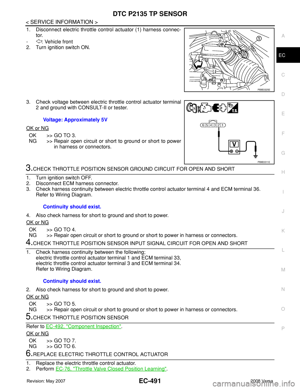
1. Disconnect electric throttle control actuator (1) harness connec-
tor.
- : Vehicle front
2. Turn ignition switch ON.
3. Check voltage between electric throttle control actuator terminal
2 and ground with CONSULT-II or tester.
OK or NG
OK >> GO TO 3.
NG >> Repair open circuit or short to ground or short to power
in harness or connectors.
3.CHECK THROTTLE POSITION SENSOR GROUND CIRCUIT FOR OPEN AND SHORT
1. Turn ignition switch OFF.
2. Disconnect ECM harness connector.
3. Check harness continuity between electric throttle control actuator terminal 4 and ECM terminal 36.
Refer to Wiring Diagram.
4. Also check harness for short to ground and short to power.
OK or NG
OK >> GO TO 4.
NG >> Repair open circuit or short to ground or short to power in harness or connectors.
4.CHECK THROTTLE POSITION SENSOR INPUT SIGNAL CIRCUIT FOR OPEN AND SHORT
1. Check harness continuity between the following;
electric throttle control actuator terminal 1 and ECM terminal 33,
electric throttle control actuator terminal 3 and ECM terminal 34.
Refer to Wiring Diagram.
2. Also check harness for short to ground and short to power.
OK or NG
OK >> GO TO 5.
NG >> Repair open circuit or short to ground or short to power in harness or connectors.
5.CHECK THROTTLE POSITION SENSOR
Refer to EC-492, "
Component Inspection".
OK or NG
OK >> GO TO 7.
NG >> GO TO 6.
6.REPLACE ELECTRIC THROTTLE CONTROL ACTUATOR
1. Replace the electric throttle control actuator.
2. Perform EC-76, "
Throttle Valve Closed Position Learning".
PBIB3325E
Voltage: Approximately 5V
PBIB3311E
Continuity should exist.
Continuity should exist.
Page 1566 of 2771
EC-492
< SERVICE INFORMATION >
DTC P2135 TP SENSOR
3. Perform EC-76, "Idle Air Volume Learning".
>>INSPECTION END
7.CHECK INTERMITTENT INCIDENT
Refer to EC-136
.
>>INSPECTION END
Component InspectionINFOID:0000000001703031
THROTTLE POSITION SENSOR
1. Reconnect all harness connectors disconnected.
2. Perform EC-76, "
Throttle Valve Closed Position Learning".
3. Turn ignition switch ON.
4. Set shift lever to D position (A/T, CVT) or 1st position (M/T).
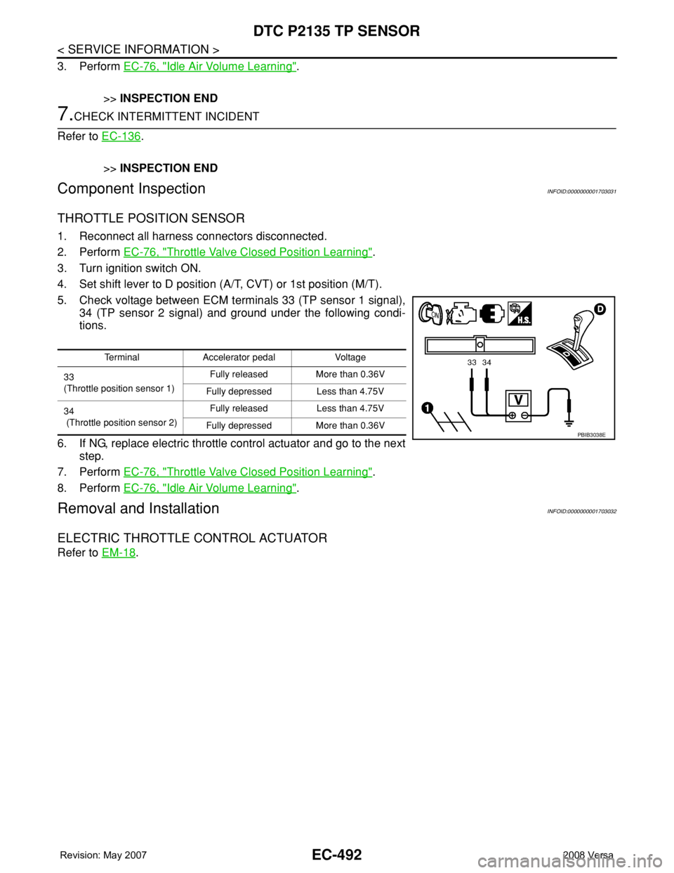
5. Check voltage between ECM terminals 33 (TP sensor 1 signal),
34 (TP sensor 2 signal) and ground under the following condi-
tions.
6. If NG, replace electric throttle control actuator and go to the next
step.
7. Perform EC-76, "
Throttle Valve Closed Position Learning".
8. Perform EC-76, "
Idle Air Volume Learning".
Removal and InstallationINFOID:0000000001703032
ELECTRIC THROTTLE CONTROL ACTUATOR
Refer to EM-18.
Terminal Accelerator pedal Voltage
33
(Throttle position sensor 1)Fully released More than 0.36V
Fully depressed Less than 4.75V
34
(Throttle position sensor 2)Fully released Less than 4.75V
Fully depressed More than 0.36V
PBIB3038E
Page 1572 of 2771
EC-498
< SERVICE INFORMATION >
DTC P2138 APP SENSOR
OK or NG
OK >> GO TO 6.
NG >> Repair short to ground or short to power in harness or connectors.
6.CHECK COMPONENTS
Check the following.
• Crankshaft position sensor (POS) (Refer to EC-301, "
Component Inspection".)
• EVAP control system pressure sensor (Refer to EC-353, "
Component Inspection".)
• Refrigerant pressure sensor (Refer to MTC-22
.)
OK or NG
OK >> GO TO 11.
NG >> Replace malfunctioning component.
7.CHECK APP SENSOR GROUND CIRCUIT FOR OPEN AND SHORT
1. Turn ignition switch OFF.
2. Disconnect ECM harness connector.
3. Check harness continuity between the following;
ECM terminal 111 and APP sensor terminal 2,
ECM terminal 104 and APP sensor terminal 1.
Refer to Wiring Diagram.
4. Also check harness for short to ground and short to power.
OK or NG
OK >> GO TO 8.
NG >> Repair open circuit or short to ground or short to power in harness or connectors.
8.CHECK APP SENSOR INPUT SIGNAL CIRCUIT FOR OPEN AND SHORT
1. Check harness continuity between the following;
ECM terminal 110 and APP sensor terminal 3,
ECM terminal 103 and APP sensor terminal 6.
Refer to Wiring Diagram.
2. Also check harness for short to ground and short to power.
OK or NG
OK >> GO TO 9.
NG >> Repair open circuit or short to ground or short to power in harness or connectors.
9.CHECK APP SENSOR
Refer to EC-499, "
Component Inspection".
OK or NG
OK >> GO TO 11.
NG >> GO TO 10.
10.REPLACE ACCELERATOR PEDAL ASSEMBLY
1. Replace accelerator pedal assembly.
2. Perform EC-76, "
Accelerator Pedal Released Position Learning".
3. Perform EC-76, "
Throttle Valve Closed Position Learning".
4. Perform EC-76, "
Idle Air Volume Learning".
ECM terminal Sensor terminalReference Wiring Diagram
74 Refrigerant pressure sensor terminal 3EC-542, "
Wiring Diagram"
75 Crankshaft position sensor (POS) terminal 1EC-297, "Wiring Diagram"
76 EVAP control system pressure sensor terminal 3EC-357, "Wiring Diagram"
102 APP sensor terminal 5EC-495, "Wiring Diagram"
Continuity should exist.
Continuity should exist.
Page 1573 of 2771
DTC P2138 APP SENSOR
EC-499
< SERVICE INFORMATION >
C
D
E
F
G
H
I
J
K
L
MA
EC
N
P O
>>INSPECTION END
11 .CHECK INTERMITTENT INCIDENT
Refer to EC-136
.
>>INSPECTION END
Component InspectionINFOID:0000000001703039
ACCELERATOR PEDAL POSITION SENSOR
1. Reconnect all harness connectors disconnected.
2. Turn ignition switch ON.
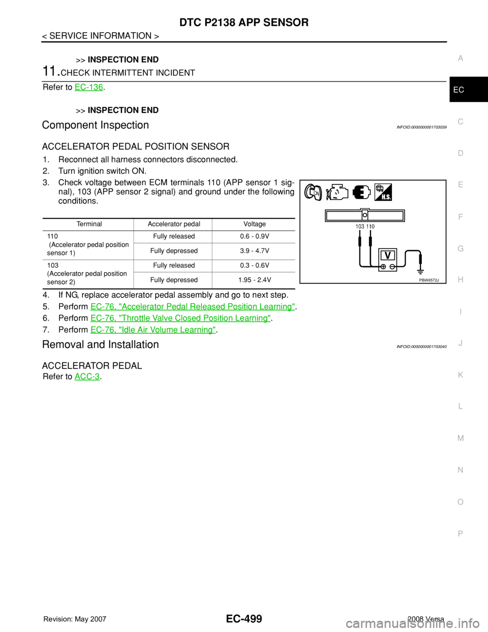
3. Check voltage between ECM terminals 110 (APP sensor 1 sig-
nal), 103 (APP sensor 2 signal) and ground under the following
conditions.
4. If NG, replace accelerator pedal assembly and go to next step.
5. Perform EC-76, "
Accelerator Pedal Released Position Learning".
6. Perform EC-76, "
Throttle Valve Closed Position Learning".
7. Perform EC-76, "
Idle Air Volume Learning".
Removal and InstallationINFOID:0000000001703040
ACCELERATOR PEDAL
Refer to ACC-3.
Terminal Accelerator pedal Voltage
11 0
(Accelerator pedal position
sensor 1)Fully released 0.6 - 0.9V
Fully depressed 3.9 - 4.7V
103
(Accelerator pedal position
sensor 2)Fully released 0.3 - 0.6V
Fully depressed 1.95 - 2.4V
PBIA9572J