2008 NISSAN LATIO turn signal
[x] Cancel search: turn signalPage 1930 of 2771
POWER WINDOW SYSTEM
GW-29
< SERVICE INFORMATION >
C
D
E
F
G
H
J
K
L
MA
B
GW
N
O
P
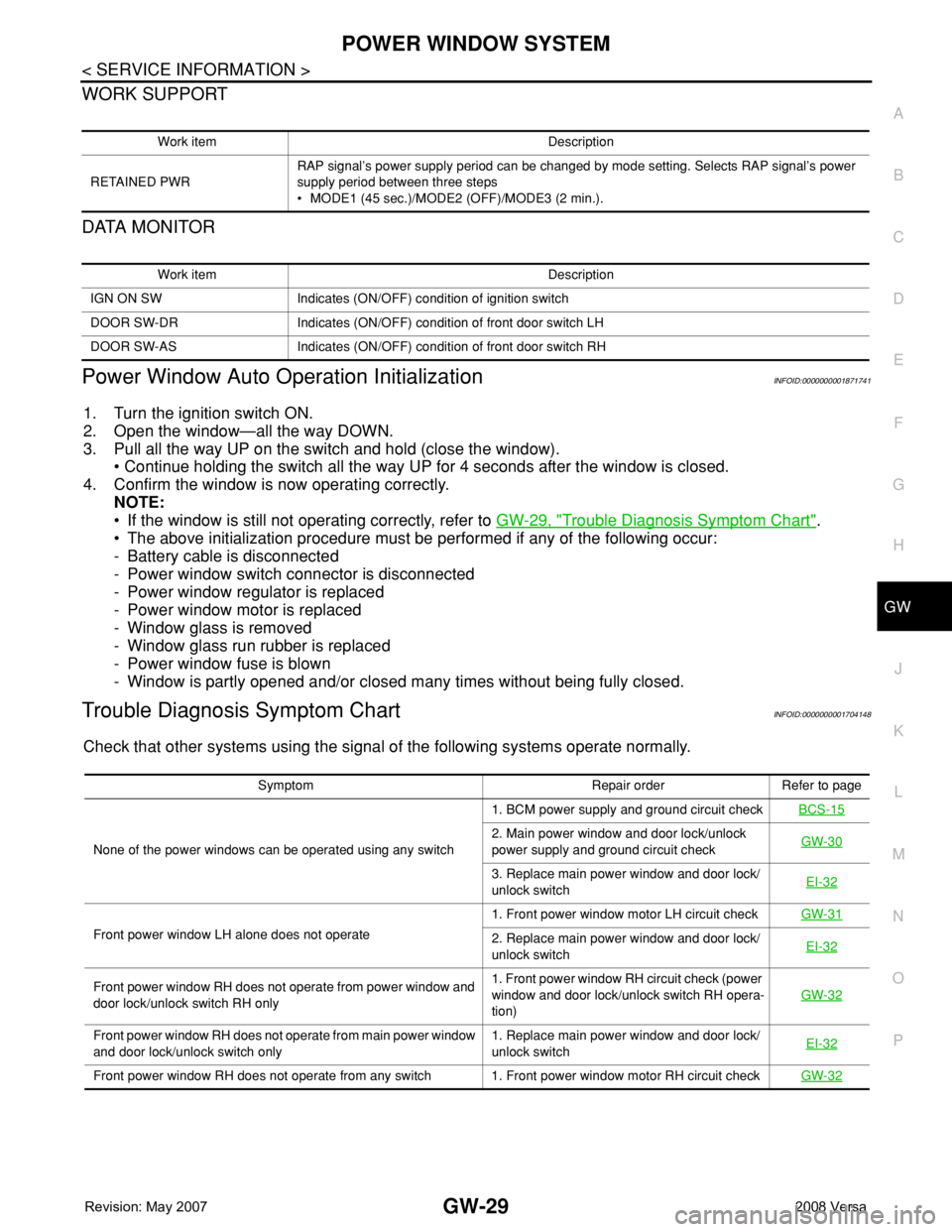
WORK SUPPORT
DATA MONITOR
Power Window Auto Operation InitializationINFOID:0000000001871741
1. Turn the ignition switch ON.
2. Open the window—all the way DOWN.
3. Pull all the way UP on the switch and hold (close the window).
• Continue holding the switch all the way UP for 4 seconds after the window is closed.
4. Confirm the window is now operating correctly.
NOTE:
• If the window is still not operating correctly, refer to GW-29, "
Trouble Diagnosis Symptom Chart".
• The above initialization procedure must be performed if any of the following occur:
- Battery cable is disconnected
- Power window switch connector is disconnected
- Power window regulator is replaced
- Power window motor is replaced
- Window glass is removed
- Window glass run rubber is replaced
- Power window fuse is blown
- Window is partly opened and/or closed many times without being fully closed.
Trouble Diagnosis Symptom ChartINFOID:0000000001704148
Check that other systems using the signal of the following systems operate normally.
Work item Description
RETAINED PWRRAP signal’s power supply period can be changed by mode setting. Selects RAP signal’s power
supply period between three steps
• MODE1 (45 sec.)/MODE2 (OFF)/MODE3 (2 min.).
Work item Description
IGN ON SW Indicates (ON/OFF) condition of ignition switch
DOOR SW-DR Indicates (ON/OFF) condition of front door switch LH
DOOR SW-AS Indicates (ON/OFF) condition of front door switch RH
Symptom Repair order Refer to page
None of the power windows can be operated using any switch1. BCM power supply and ground circuit checkBCS-15
2. Main power window and door lock/unlock
power supply and ground circuit checkGW-30
3. Replace main power window and door lock/
unlock switchEI-32
Front power window LH alone does not operate1. Front power window motor LH circuit checkGW-312. Replace main power window and door lock/
unlock switchEI-32
Front power window RH does not operate from power window and
door lock/unlock switch RH only1. Front power window RH circuit check (power
window and door lock/unlock switch RH opera-
tion)GW-32
Front power window RH does not operate from main power window
and door lock/unlock switch only1. Replace main power window and door lock/
unlock switchEI-32
Front power window RH does not operate from any switch 1. Front power window motor RH circuit checkGW-32
Page 1932 of 2771
POWER WINDOW SYSTEM
GW-31
< SERVICE INFORMATION >
C
D
E
F
G
H
J
K
L
MA
B
GW
N
O
P
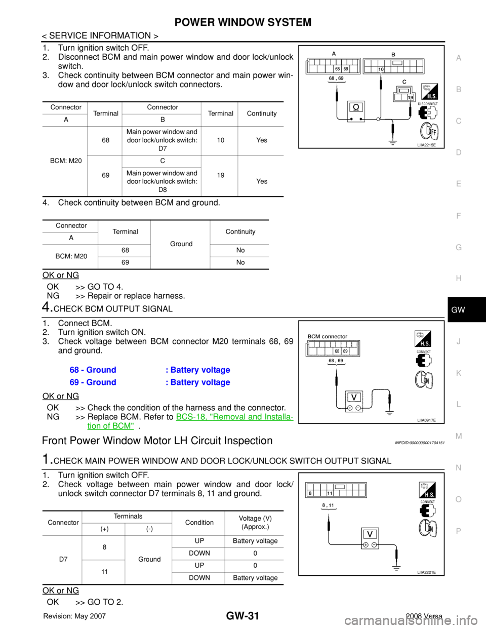
1. Turn ignition switch OFF.
2. Disconnect BCM and main power window and door lock/unlock
switch.
3. Check continuity between BCM connector and main power win-
dow and door lock/unlock switch connectors.
4. Check continuity between BCM and ground.
OK or NG
OK >> GO TO 4.
NG >> Repair or replace harness.
4.CHECK BCM OUTPUT SIGNAL
1. Connect BCM.
2. Turn ignition switch ON.
3. Check voltage between BCM connector M20 terminals 68, 69
and ground.
OK or NG
OK >> Check the condition of the harness and the connector.
NG >> Replace BCM. Refer to BCS-18, "
Removal and Installa-
tion of BCM" .
Front Power Window Motor LH Circuit InspectionINFOID:0000000001704151
1.CHECK MAIN POWER WINDOW AND DOOR LOCK/UNLOCK SWITCH OUTPUT SIGNAL
1. Turn ignition switch OFF.
2. Check voltage between main power window and door lock/
unlock switch connector D7 terminals 8, 11 and ground.
OK or NG
OK >> GO TO 2.
Connector
Te r m i n a lConnector
Terminal Continuity
AB
BCM: M2068Main power window and
door lock/unlock switch:
D710 Yes
69C
19 Main power window and
door lock/unlock switch:
D8Ye s
Connector
Te r m i n a l
GroundContinuity
A
BCM: M2068 No
69 No
LIIA2215E
68 - Ground : Battery voltage
69 - Ground : Battery voltage
LIIA0917E
ConnectorTe r m i n a l s
ConditionVoltage (V)
(Approx.)
(+) (-)
D78
GroundUP Battery voltage
DOWN 0
11UP 0
DOWN Battery voltage
LIIA2221E
Page 1933 of 2771
GW-32
< SERVICE INFORMATION >
POWER WINDOW SYSTEM
NG >> Replace main power window and door lock/unlock switch. Refer to EI-32, "Removal and Installa-
tion" .
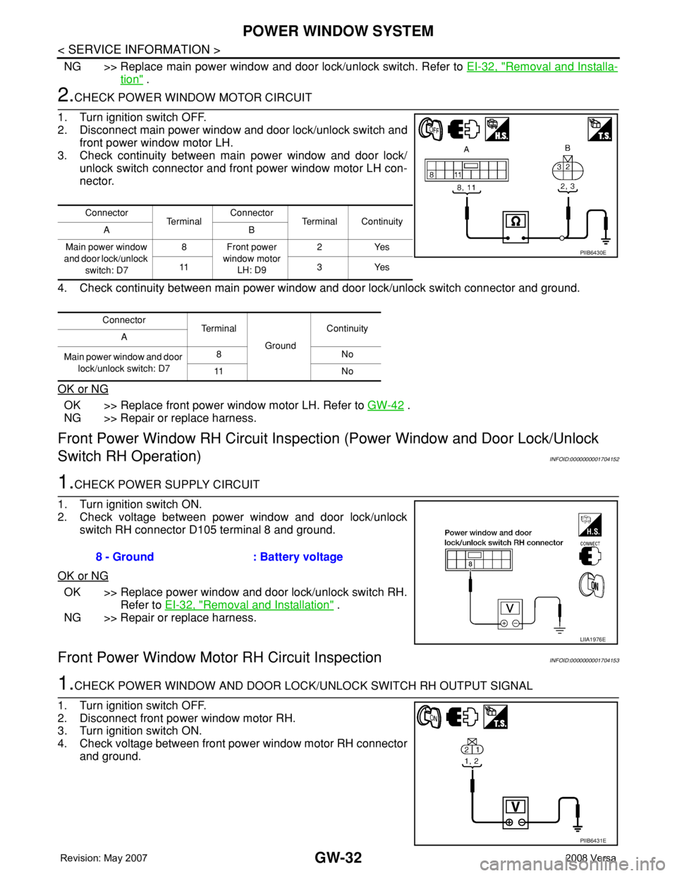
2.CHECK POWER WINDOW MOTOR CIRCUIT
1. Turn ignition switch OFF.
2. Disconnect main power window and door lock/unlock switch and
front power window motor LH.
3. Check continuity between main power window and door lock/
unlock switch connector and front power window motor LH con-
nector.
4. Check continuity between main power window and door lock/unlock switch connector and ground.
OK or NG
OK >> Replace front power window motor LH. Refer to GW-42 .
NG >> Repair or replace harness.
Front Power Window RH Circuit Inspection (Power Window and Door Lock/Unlock
Switch RH Operation)
INFOID:0000000001704152
1.CHECK POWER SUPPLY CIRCUIT
1. Turn ignition switch ON.
2. Check voltage between power window and door lock/unlock
switch RH connector D105 terminal 8 and ground.
OK or NG
OK >> Replace power window and door lock/unlock switch RH.
Refer to EI-32, "
Removal and Installation" .
NG >> Repair or replace harness.
Front Power Window Motor RH Circuit InspectionINFOID:0000000001704153
1.CHECK POWER WINDOW AND DOOR LOCK/UNLOCK SWITCH RH OUTPUT SIGNAL
1. Turn ignition switch OFF.
2. Disconnect front power window motor RH.
3. Turn ignition switch ON.
4. Check voltage between front power window motor RH connector
and ground.
Connector
Te r m i n a lConnector
Terminal Continuity
AB
Main power window
and door lock/unlock
switch: D78 Front power
window motor
LH: D92Yes
11 3 Ye s
Connector
Terminal
GroundContinuity
A
Main power window and door
lock/unlock switch: D78No
11 N o
PIIB6430E
8 - Ground : Battery voltage
LIIA1976E
PIIB6431E
Page 1936 of 2771
POWER WINDOW SYSTEM
GW-35
< SERVICE INFORMATION >
C
D
E
F
G
H
J
K
L
MA
B
GW
N
O
P
OK or NG
OK >> Replace main power window and door lock/unlock switch. Refer to EI-32, "Removal and Installa-
tion" .
NG >> Repair or replace harness.
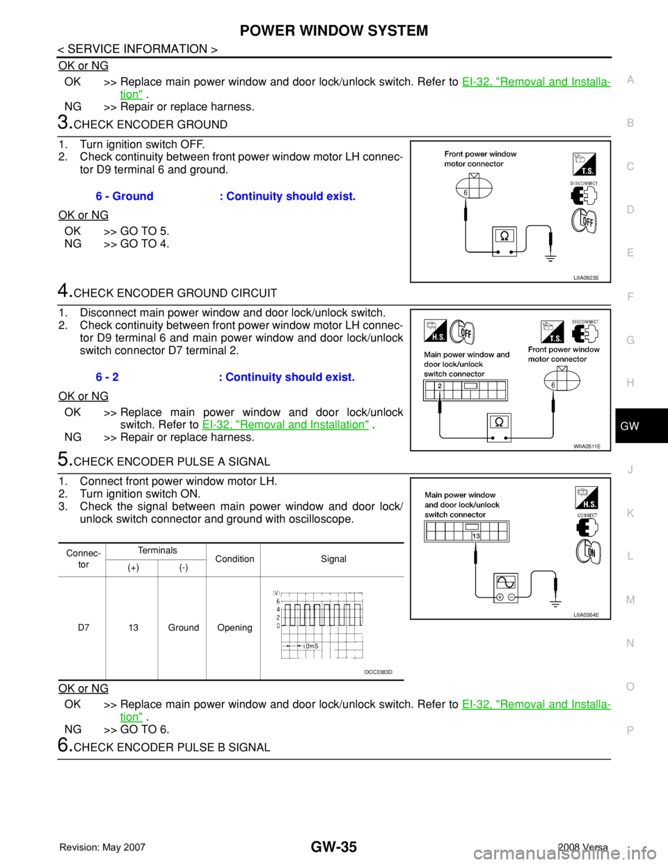
3.CHECK ENCODER GROUND
1. Turn ignition switch OFF.
2. Check continuity between front power window motor LH connec-
tor D9 terminal 6 and ground.
OK or NG
OK >> GO TO 5.
NG >> GO TO 4.
4.CHECK ENCODER GROUND CIRCUIT
1. Disconnect main power window and door lock/unlock switch.
2. Check continuity between front power window motor LH connec-
tor D9 terminal 6 and main power window and door lock/unlock
switch connector D7 terminal 2.
OK or NG
OK >> Replace main power window and door lock/unlock
switch. Refer to EI-32, "
Removal and Installation" .
NG >> Repair or replace harness.
5.CHECK ENCODER PULSE A SIGNAL
1. Connect front power window motor LH.
2. Turn ignition switch ON.
3. Check the signal between main power window and door lock/
unlock switch connector and ground with oscilloscope.
OK or NG
OK >> Replace main power window and door lock/unlock switch. Refer to EI-32, "Removal and Installa-
tion" .
NG >> GO TO 6.
6.CHECK ENCODER PULSE B SIGNAL6 - Ground : Continuity should exist.
LIIA0923E
6 - 2 : Continuity should exist.
WIIA0511E
Connec-
torTe r m i n a l s
Condition Signal
(+) (-)
D7 13 Ground Opening
LIIA0364E
OCC3383D
Page 1937 of 2771
GW-36
< SERVICE INFORMATION >
POWER WINDOW SYSTEM
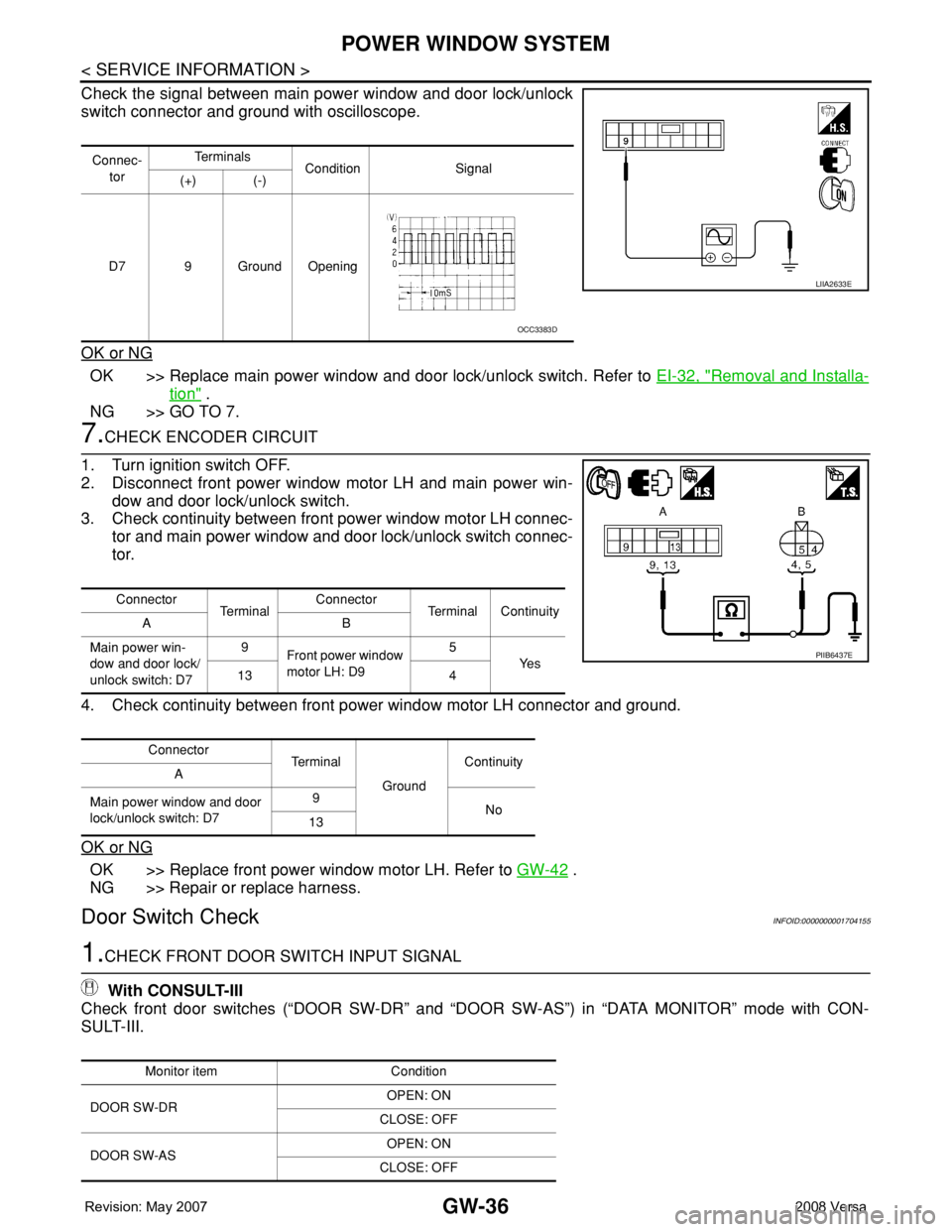
Check the signal between main power window and door lock/unlock
switch connector and ground with oscilloscope.
OK or NG
OK >> Replace main power window and door lock/unlock switch. Refer to EI-32, "Removal and Installa-
tion" .
NG >> GO TO 7.
7.CHECK ENCODER CIRCUIT
1. Turn ignition switch OFF.
2. Disconnect front power window motor LH and main power win-
dow and door lock/unlock switch.
3. Check continuity between front power window motor LH connec-
tor and main power window and door lock/unlock switch connec-
tor.
4. Check continuity between front power window motor LH connector and ground.
OK or NG
OK >> Replace front power window motor LH. Refer to GW-42 .
NG >> Repair or replace harness.
Door Switch CheckINFOID:0000000001704155
1.CHECK FRONT DOOR SWITCH INPUT SIGNAL
With CONSULT-III
Check front door switches (“DOOR SW-DR” and “DOOR SW-AS”) in “DATA MONITOR” mode with CON-
SULT-III.
Connec-
torTe r m i n a l s
Condition Signal
(+) (-)
D7 9 Ground Opening
LIIA2633E
OCC3383D
Connector
Te r m i n a lConnector
Terminal Continuity
AB
Main power win-
dow and door lock/
unlock switch: D79
Front power window
motor LH: D95
Ye s
13 4
Connector
Te r m i n a l
GroundContinuity
A
Main power window and door
lock/unlock switch: D79
No
13
PIIB6437E
Monitor item Condition
DOOR SW-DROPEN: ON
CLOSE: OFF
DOOR SW-ASOPEN: ON
CLOSE: OFF
Page 1939 of 2771
GW-38
< SERVICE INFORMATION >
POWER WINDOW SYSTEM
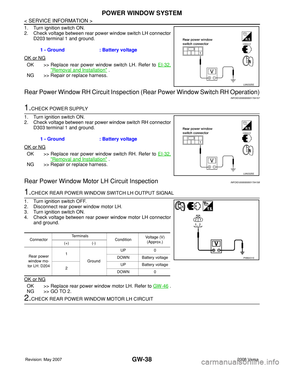
1. Turn ignition switch ON.
2. Check voltage between rear power window switch LH connector
D203 terminal 1 and ground.
OK or NG
OK >> Replace rear power window switch LH. Refer to EI-32,
"Removal and Installation" .
NG >> Repair or replace harness.
Rear Power Window RH Circuit Inspection (Rear Power Window Switch RH Operation)
INFOID:0000000001704157
1.CHECK POWER SUPPLY
1. Turn ignition switch ON.
2. Check voltage between rear power window switch RH connector
D303 terminal 1 and ground.
OK or NG
OK >> Replace rear power window switch RH. Refer to EI-32,
"Removal and Installation" .
NG >> Repair or replace harness.
Rear Power Window Motor LH Circuit InspectionINFOID:0000000001704158
1.CHECK REAR POWER WINDOW SWITCH LH OUTPUT SIGNAL
1. Turn ignition switch OFF.
2. Disconnect rear power window motor LH.
3. Turn ignition switch ON.
4. Check voltage between rear power window motor LH connector
and ground.
OK or NG
OK >> Replace rear power window motor LH. Refer to GW-46 .
NG >> GO TO 2.
2.CHECK REAR POWER WINDOW MOTOR LH CIRCUIT1 - Ground : Battery voltage
LIIA0325E
1 - Ground : Battery voltage
LIIA0325E
ConnectorTe r m i n a l s
ConditionVoltage (V)
(Approx.)
(+) (-)
Rear power
window mo-
tor LH: D2041
GroundUP 0
DOWN Battery voltage
2UP Battery voltage
DOWN 0
PIIB6431E
Page 1941 of 2771
GW-40
< SERVICE INFORMATION >
POWER WINDOW SYSTEM
NG >> Repair or replace harness.
Rear Power Window Motor RH Circuit InspectionINFOID:0000000001704159
1.CHECK REAR POWER WINDOW SWITCH RH OUTPUT SIGNAL
1. Turn ignition switch OFF.
2. Disconnect rear power window motor RH.
3. Turn ignition switch ON.
4. Check voltage between rear power window motor RH connector
and ground.
OK or NG
OK >> Replace rear power window motor RH. Refer to GW-46 .
NG >> GO TO 2.
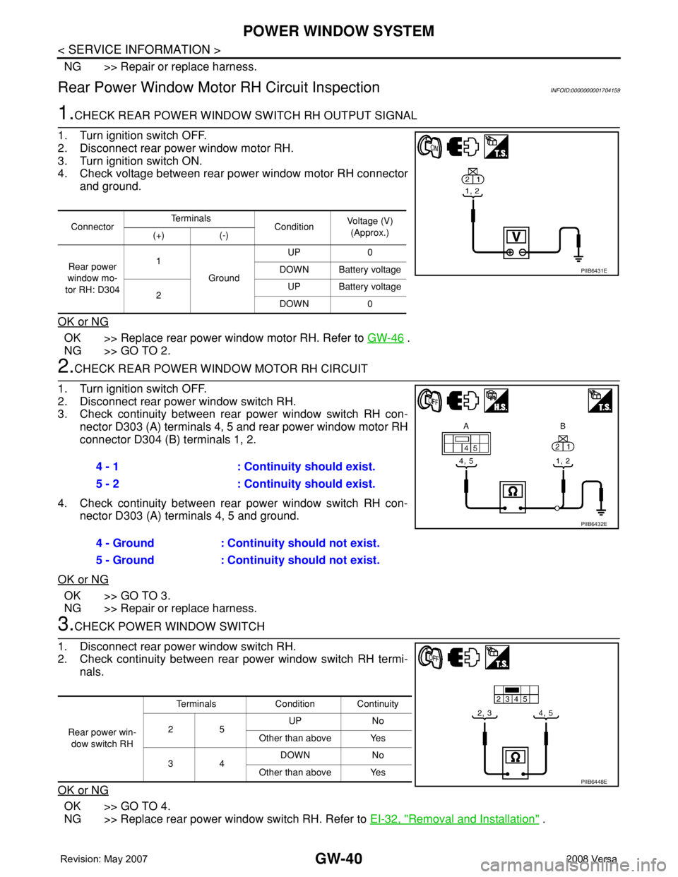
2.CHECK REAR POWER WINDOW MOTOR RH CIRCUIT
1. Turn ignition switch OFF.
2. Disconnect rear power window switch RH.
3. Check continuity between rear power window switch RH con-
nector D303 (A) terminals 4, 5 and rear power window motor RH
connector D304 (B) terminals 1, 2.
4. Check continuity between rear power window switch RH con-
nector D303 (A) terminals 4, 5 and ground.
OK or NG
OK >> GO TO 3.
NG >> Repair or replace harness.
3.CHECK POWER WINDOW SWITCH
1. Disconnect rear power window switch RH.
2. Check continuity between rear power window switch RH termi-
nals.
OK or NG
OK >> GO TO 4.
NG >> Replace rear power window switch RH. Refer to EI-32, "
Removal and Installation" .
ConnectorTe r m i n a l s
ConditionVoltage (V)
(Approx.)
(+) (-)
Rear power
window mo-
tor RH: D3041
GroundUP 0
DOWN Battery voltage
2UP Battery voltage
DOWN 0
PIIB6431E
4 - 1 : Continuity should exist.
5 - 2 : Continuity should exist.
4 - Ground : Continuity should not exist.
5 - Ground : Continuity should not exist.
PIIB6432E
Rear power win-
dow switch RHTerminals Condition Continuity
25UP No
Other than above Yes
34DOWN No
Other than above Yes
PIIB6448E
Page 1951 of 2771

GW-50
< SERVICE INFORMATION >
REAR WINDOW DEFOGGER
Power is supplied at all times
• through 15A fuses (No. 46 and 47, located in the IPDM E/R)
• to rear window defogger relay
• through 10A fuse [No. 5 (with heated mirrors), located in the fuse block (J/B)]
• to heated mirror relay terminal 3
• through 40A fusible link (letter g , located in the fuse and fusible link box)
• to BCM terminal 70.
With the ignition switch turned to ON or START position, power is supplied
• through ignition relay
• to rear window defogger relay (located in the IPDM E/R)
• through 10A fuse [No. 6, located in the fuse block (J/B)]
• to BCM terminal 38.
Ground is supplied
• to BCM terminal 67 and
• to front air control terminal 8
• through body grounds M57 and M61
• to IPDM E/R terminals 39 and 59
• through body grounds E15 and E24.
When front air control (rear window defogger switch) is turned to ON, ground is supplied
• to BCM terminal 9
• through front air control terminal 3
• through front air control terminal 8
• through body grounds M57 and M61.
Then rear window defogger switch is illuminated.
Then BCM recognizes that rear window defogger switch is turned to ON.
Then it sends rear window defogger switch signals to IPDM E/R via CAN communication (CAN-H, CAN-L).
When IPDM E/R receives rear window defogger switch signals, ground is supplied
• to rear window defogger relay (located in the IPDM E/R)
• through IPDM E/R terminals 39 and 59
• through body grounds E15 and E24
Then rear window defogger relay is energized.
With power and ground supplied, rear window defogger filaments heat and defog the rear window.
When rear window defogger relay is turned to ON (with heated mirrors), power is supplied
• through heated mirror relay terminal 5
• to door mirror (LH and RH) terminal 1.
Door mirror (LH and RH) is grounded through body grounds M57 and M61.
With power and ground supplied, rear window defogger filaments heat and defog the rear window and door
mirror filaments heat and defog the mirrors.
CAN Communication System DescriptionINFOID:0000000001704168
Refer to LAN-6, "System Description".