2008 NISSAN LATIO display
[x] Cancel search: displayPage 2148 of 2771
HEADLAMP (FOR USA)
LT-11
< SERVICE INFORMATION >
C
D
E
F
G
H
I
J
L
MA
B
LT
N
O
P
How to Perform Trouble DiagnosisINFOID:0000000001704367
1. Confirm the symptom or customer complaint.
2. Understand operation, description and function description. Refer to LT- 4 , "
System Description" .
3. Perform the Preliminary Check. Refer to LT- 11 , "
Preliminary Check" .
4. Check symptom and repair or replace the cause of the malfunction.
5. Do the headlamps operate normally? If YES, GO TO 6. If NO, GO TO 4.
6. INSPECTION END
Preliminary CheckINFOID:0000000001704368
CHECK POWER SUPPLY AND GROUND CIRCUIT FOR BCM
Refer to BCS-15, "BCM Power Supply and Ground Circuit Inspection" .
CHECK POWER SUPPLY AND GROUND CIRCUIT FOR IPDM E/R
Refer to PG-25, "IPDM E/R Power/Ground Circuit Inspection" .
CONSULT-III Function (BCM)INFOID:0000000001704369
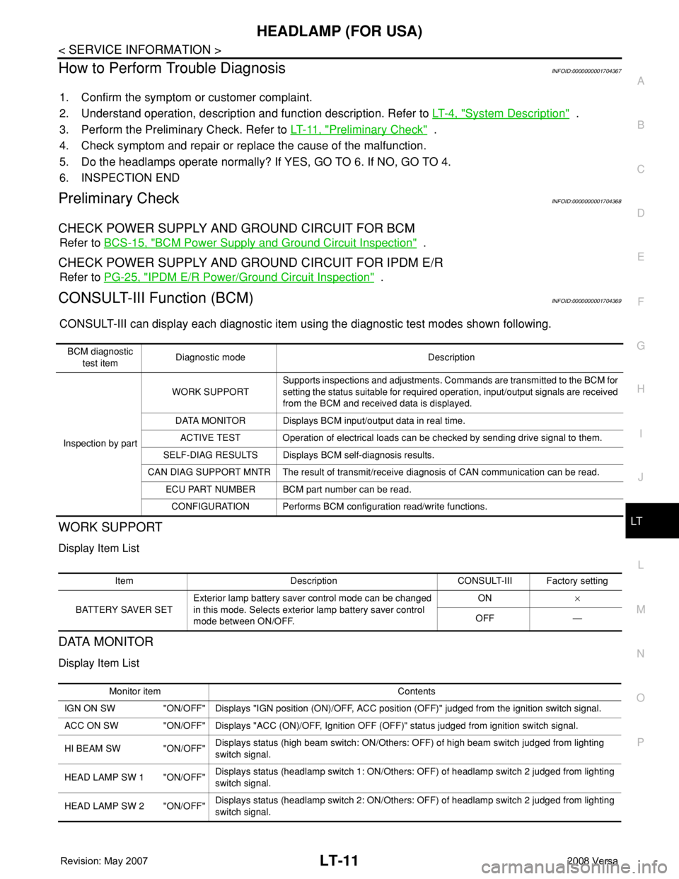
CONSULT-III can display each diagnostic item using the diagnostic test modes shown following.
WORK SUPPORT
Display Item List
DATA MONITOR
Display Item List
BCM diagnostic
test itemDiagnostic mode Description
Inspection by partWORK SUPPORTSupports inspections and adjustments. Commands are transmitted to the BCM for
setting the status suitable for required operation, input/output signals are received
from the BCM and received data is displayed.
DATA MONITOR Displays BCM input/output data in real time.
ACTIVE TEST Operation of electrical loads can be checked by sending drive signal to them.
SELF-DIAG RESULTS Displays BCM self-diagnosis results.
CAN DIAG SUPPORT MNTR The result of transmit/receive diagnosis of CAN communication can be read.
ECU PART NUMBER BCM part number can be read.
CONFIGURATION Performs BCM configuration read/write functions.
Item Description CONSULT-III Factory setting
BATTERY SAVER SETExterior lamp battery saver control mode can be changed
in this mode. Selects exterior lamp battery saver control
mode between ON/OFF.ON×
OFF —
Monitor item Contents
IGN ON SW "ON/OFF" Displays "IGN position (ON)/OFF, ACC position (OFF)" judged from the ignition switch signal.
ACC ON SW "ON/OFF" Displays "ACC (ON)/OFF, Ignition OFF (OFF)" status judged from ignition switch signal.
HI BEAM SW "ON/OFF"Displays status (high beam switch: ON/Others: OFF) of high beam switch judged from lighting
switch signal.
HEAD LAMP SW 1 "ON/OFF"Displays status (headlamp switch 1: ON/Others: OFF) of headlamp switch 2 judged from lighting
switch signal.
HEAD LAMP SW 2 "ON/OFF"Displays status (headlamp switch 2: ON/Others: OFF) of headlamp switch 2 judged from lighting
switch signal.
Page 2149 of 2771

LT-12
< SERVICE INFORMATION >
HEADLAMP (FOR USA)
Note 1: Vehicles without daytime light system may display this item, but cannot monitor it.
ACTIVE TEST
Display Item List
SELF-DIAGNOSTIC RESULTS
Display Item List
CONSULT-III Function (IPDM E/R)INFOID:0000000001704370
CONSULT-III can display each diagnostic item using the diagnostic test modes shown following.
DATA MONITOR
All Items, Main Items, Select Item Menu
LIGHT SW 1ST "ON/OFF"Displays status (lighting switch 1st position: ON/Others: OFF) of lighting switch judged from lighting
switch signal.
PASSING SW "ON/OFF"Displays status (flash-to-pass switch: ON/Others: OFF) of flash-to-pass switch judged from lighting
switch signal.
FR FOG SW "ON/OFF"Displays status (front fog lamp switch: ON/Others: OFF) of front fog lamp switch judged from light-
ing switch signal.
DOOR SW - DR "ON/OFF"Displays status of the front door LH as judged from the front door switch LH signal. (Door is open:
ON/Door is closed: OFF)
DOOR SW - AS "ON/OFF"Displays status of the front door RH as judged from the front door switch RH signal. (Door is open:
ON/Door is closed: OFF)
DOOR SW - RR "ON/OFF"Displays status of the rear door as judged from the rear door switch (RH) signal. (Door is open:
ON/Door is closed: OFF)
DOOR SW - RL "ON/OFF"Displays status of the rear door as judged from the rear door switch (LH) signal. (Door is open: ON/
Door is closed: OFF)
BACK DOOR SW "ON/OFF"Displays status of the back door as judged from the back door switch signal. (Door is open: ON/
Door is closed: OFF)
TURN SIGNAL R "ON/OFF" Displays status (Turn right: ON/Others: OFF) as judged from lighting switch signal.
TURN SIGNAL L "ON/OFF" Displays status (Turn left: ON/Others: OFF) as judged from lighting switch signal.
ENGINE RUN
Note 1"ON/OFF" Displays status (Engine running: ON/Others: OFF) as judged from engine status signal.
PKB SW
Note 1"ON/OFF"Displays status (Parking brake switch: ON/Others: OFF) as judged from parking brake switch sig-
nal. Monitor item Contents
Test item Description
TAIL LAMP Allows tail lamp relay to operate by switching ON-OFF.
HEAD LAMP Allows headlamp relay (HI, LO) to operate by switching ON-OFF.
FR FOG LAMP Allows fog lamp relay to operate by switching ON-OFF.
Monitored item CONSULT-llI display Description
CAN communication CAN communication [U1000] Malfunction is detected in CAN communication.
CAN communication system CAN communication system 1 to 6 [U1000] Malfunction is detected in CAN system.
IPDM E/R diagnostic Mode Description
SELF-DIAG RESULTS Displays IPDM E/R self-diagnosis results.
DATA MONITOR Displays IPDM E/R input/output data in real time.
CAN DIAG SUPPORT MNTR The result of transmit/receive diagnosis of CAN communication can be read.
ACTIVE TEST Operation of electrical loads can be checked by sending drive signal to them.
Page 2150 of 2771
HEADLAMP (FOR USA)
LT-13
< SERVICE INFORMATION >
C
D
E
F
G
H
I
J
L
MA
B
LT
N
O
P
NOTE:
Perform monitoring of IPDM E/R data with the ignition switch ON. When the ignition switch is at ACC, the dis-
play may not be correct.
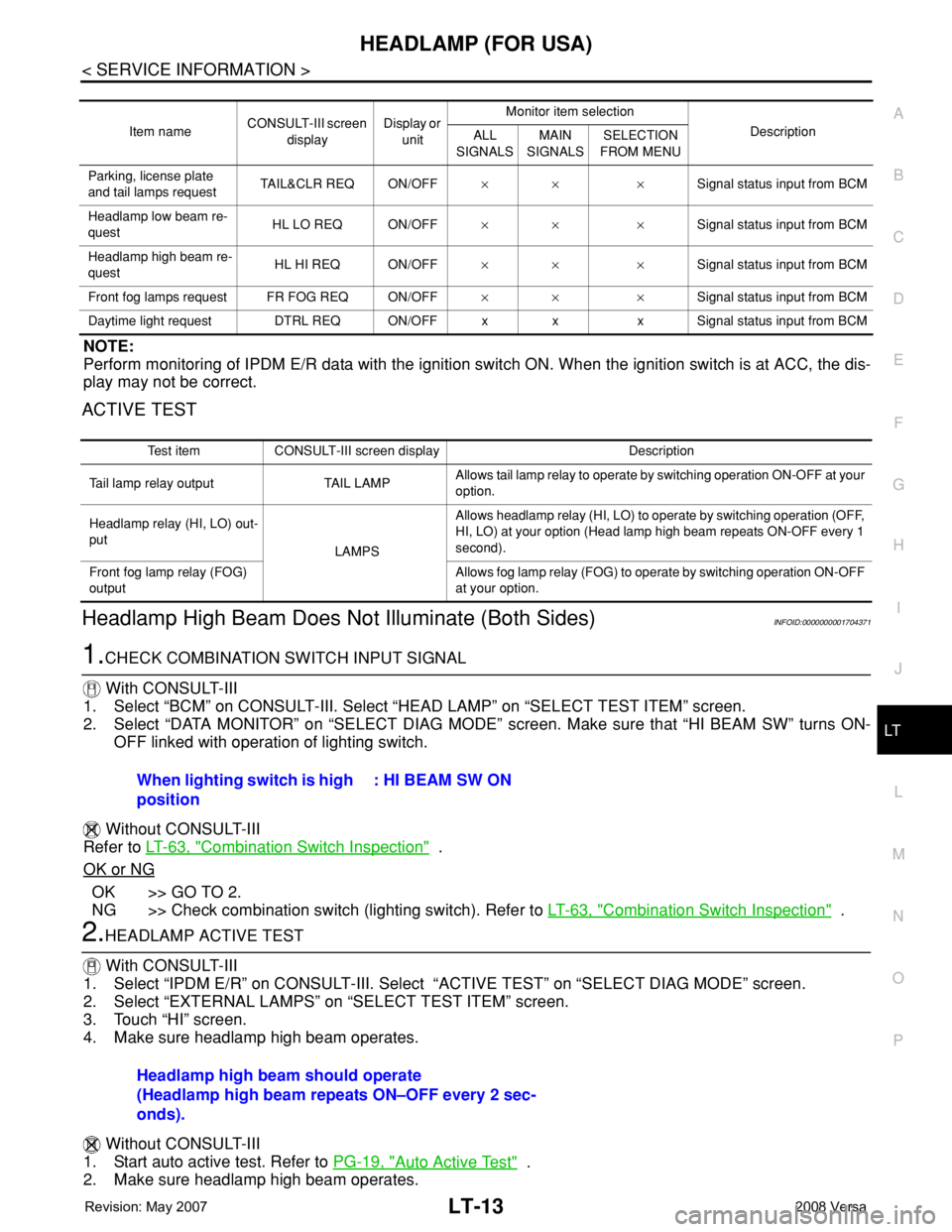
ACTIVE TEST
Headlamp High Beam Does Not Illuminate (Both Sides)INFOID:0000000001704371
1.CHECK COMBINATION SWITCH INPUT SIGNAL
With CONSULT-III
1. Select “BCM” on CONSULT-III. Select “HEAD LAMP” on “SELECT TEST ITEM” screen.
2. Select “DATA MONITOR” on “SELECT DIAG MODE” screen. Make sure that “HI BEAM SW” turns ON-
OFF linked with operation of lighting switch.
Without CONSULT-III
Refer to LT-63, "
Combination Switch Inspection" .
OK or NG
OK >> GO TO 2.
NG >> Check combination switch (lighting switch). Refer to LT-63, "
Combination Switch Inspection" .
2.HEADLAMP ACTIVE TEST
With CONSULT-III
1. Select “IPDM E/R” on CONSULT-III. Select “ACTIVE TEST” on “SELECT DIAG MODE” screen.
2. Select “EXTERNAL LAMPS” on “SELECT TEST ITEM” screen.
3. Touch “HI” screen.
4. Make sure headlamp high beam operates.
Without CONSULT-III
1. Start auto active test. Refer to PG-19, "
Auto Active Test" .
2. Make sure headlamp high beam operates.
Item nameCONSULT-III screen
displayDisplay or
unitMonitor item selection
Description
ALL
SIGNALSMAIN
SIGNALSSELECTION
FROM MENU
Parking, license plate
and tail lamps requestTAIL&CLR REQ ON/OFF×× ×Signal status input from BCM
Headlamp low beam re-
questHL LO REQ ON/OFF×× ×Signal status input from BCM
Headlamp high beam re-
questHL HI REQ ON/OFF×× ×Signal status input from BCM
Front fog lamps request FR FOG REQ ON/OFF×× ×Signal status input from BCM
Daytime light request DTRL REQ ON/OFF x x x Signal status input from BCM
Test item CONSULT-III screen display Description
Tail lamp relay output TAIL LAMPAllows tail lamp relay to operate by switching operation ON-OFF at your
option.
Headlamp relay (HI, LO) out-
put
LAMPSAllows headlamp relay (HI, LO) to operate by switching operation (OFF,
HI, LO) at your option (Head lamp high beam repeats ON-OFF every 1
second).
Front fog lamp relay (FOG)
outputAllows fog lamp relay (FOG) to operate by switching operation ON-OFF
at your option.
When lighting switch is high
position: HI BEAM SW ON
Headlamp high beam should operate
(Headlamp high beam repeats ON–OFF every 2 sec-
onds).
Page 2157 of 2771
LT-20
< SERVICE INFORMATION >
HEADLAMP (FOR USA)
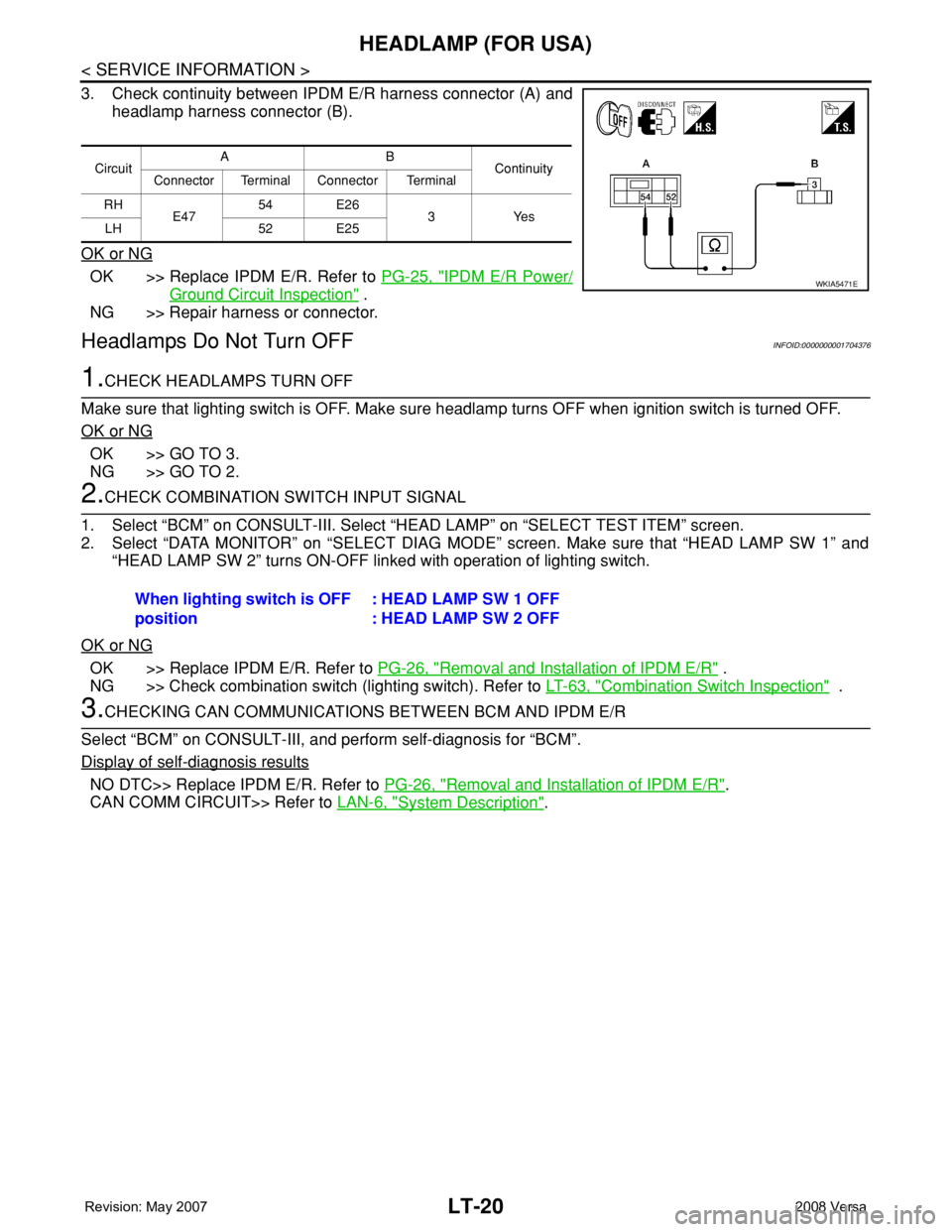
3. Check continuity between IPDM E/R harness connector (A) and
headlamp harness connector (B).
OK or NG
OK >> Replace IPDM E/R. Refer to PG-25, "IPDM E/R Power/
Ground Circuit Inspection" .
NG >> Repair harness or connector.
Headlamps Do Not Turn OFFINFOID:0000000001704376
1.CHECK HEADLAMPS TURN OFF
Make sure that lighting switch is OFF. Make sure headlamp turns OFF when ignition switch is turned OFF.
OK or NG
OK >> GO TO 3.
NG >> GO TO 2.
2.CHECK COMBINATION SWITCH INPUT SIGNAL
1. Select “BCM” on CONSULT-III. Select “HEAD LAMP” on “SELECT TEST ITEM” screen.
2. Select “DATA MONITOR” on “SELECT DIAG MODE” screen. Make sure that “HEAD LAMP SW 1” and
“HEAD LAMP SW 2” turns ON-OFF linked with operation of lighting switch.
OK or NG
OK >> Replace IPDM E/R. Refer to PG-26, "Removal and Installation of IPDM E/R" .
NG >> Check combination switch (lighting switch). Refer to LT-63, "
Combination Switch Inspection" .
3.CHECKING CAN COMMUNICATIONS BETWEEN BCM AND IPDM E/R
Select “BCM” on CONSULT-III, and perform self-diagnosis for “BCM”.
Display of self
-diagnosis results
NO DTC>> Replace IPDM E/R. Refer to PG-26, "Removal and Installation of IPDM E/R".
CAN COMM CIRCUIT>> Refer to LAN-6, "
System Description".
CircuitAB
Continuity
Connector Terminal Connector Terminal
RH
E4754 E26
3Yes
LH 52 E25
WKIA5471E
When lighting switch is OFF
position: HEAD LAMP SW 1 OFF
: HEAD LAMP SW 2 OFF
Page 2171 of 2771
LT-34
< SERVICE INFORMATION >
HEADLAMP (FOR CANADA) - DAYTIME LIGHT SYSTEM -
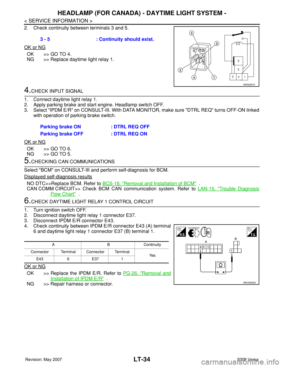
2. Check continuity between terminals 3 and 5.
OK or NG
OK >> GO TO 4.
NG >> Replace daytime light relay 1.
4.CHECK INPUT SIGNAL
1. Connect daytime light relay 1.
2. Apply parking brake and start engine. Headlamp switch OFF.
3. Select "IPDM E/R" on CONSULT-III. With DATA MONITOR, make sure "DTRL REQ" turns OFF-ON linked
with operation of parking brake switch.
OK or NG
OK >> GO TO 6.
NG >> GO TO 5.
5.CHECKING CAN COMMUNICATIONS
Select "BCM" on CONSULT-III and perform self-diagnosis for BCM.
Displayed self-diagnosis results
NO DTC>>Replace BCM. Refer to BCS-18, "Removal and Installation of BCM" .
CAN COMM CIRCUIT>> Check BCM CAN communication system. Refer to LAN-15, "
Trouble Diagnosis
Flow Chart" .
6.CHECK DAYTIME LIGHT RELAY 1 CONTROL CIRCUIT
1. Turn ignition switch OFF.
2. Disconnect daytime light relay 1 connector E37.
3. Disconnect IPDM E/R connector E43.
4. Check continuity between IPDM E/R connector E43 (A) terminal
6 and daytime light relay 1 connector E37 (B) terminal 1.
OK or NG
OK >> Replace the IPDM E/R. Refer to PG-26, "Removal and
Installation of IPDM E/R" .
NG >> Repair harness or connector. 3 - 5 : Continuity should exist.
WIIA0291E
Parking brake ON : DTRL REQ OFF
Parking brake OFF : DTRL REQ ON
ABContinuity
Connector Terminal Connector Terminal
Ye s
E43 6 E37 1
WKIA5553E
Page 2236 of 2771
INTERIOR ROOM LAMP
LT-99
< SERVICE INFORMATION >
C
D
E
F
G
H
I
J
L
MA
B
LT
N
O
P
3. Perform the preliminary check. Refer to LT-99, "Preliminary Check" .
4. Check symptom and repair or replace the cause of the malfunction.
5. Does the interior room lamp operate normally? If YES, GO TO 6. If NO, GO TO 4.
6. Inspection End
Preliminary CheckINFOID:0000000001704474
CHECK POWER SUPPLY AND GROUND CIRCUIT FOR BCM
Refer to BCS-15, "BCM Power Supply and Ground Circuit Inspection" .
CHECK POWER SUPPLY AND GROUND CIRCUIT FOR IPDM E/R
Refer to LT- 11 , "Preliminary Check" .
CONSULT-III Function (BCM)INFOID:0000000001704475
Refer to LT- 11 , "CONSULT-III Function (BCM)".
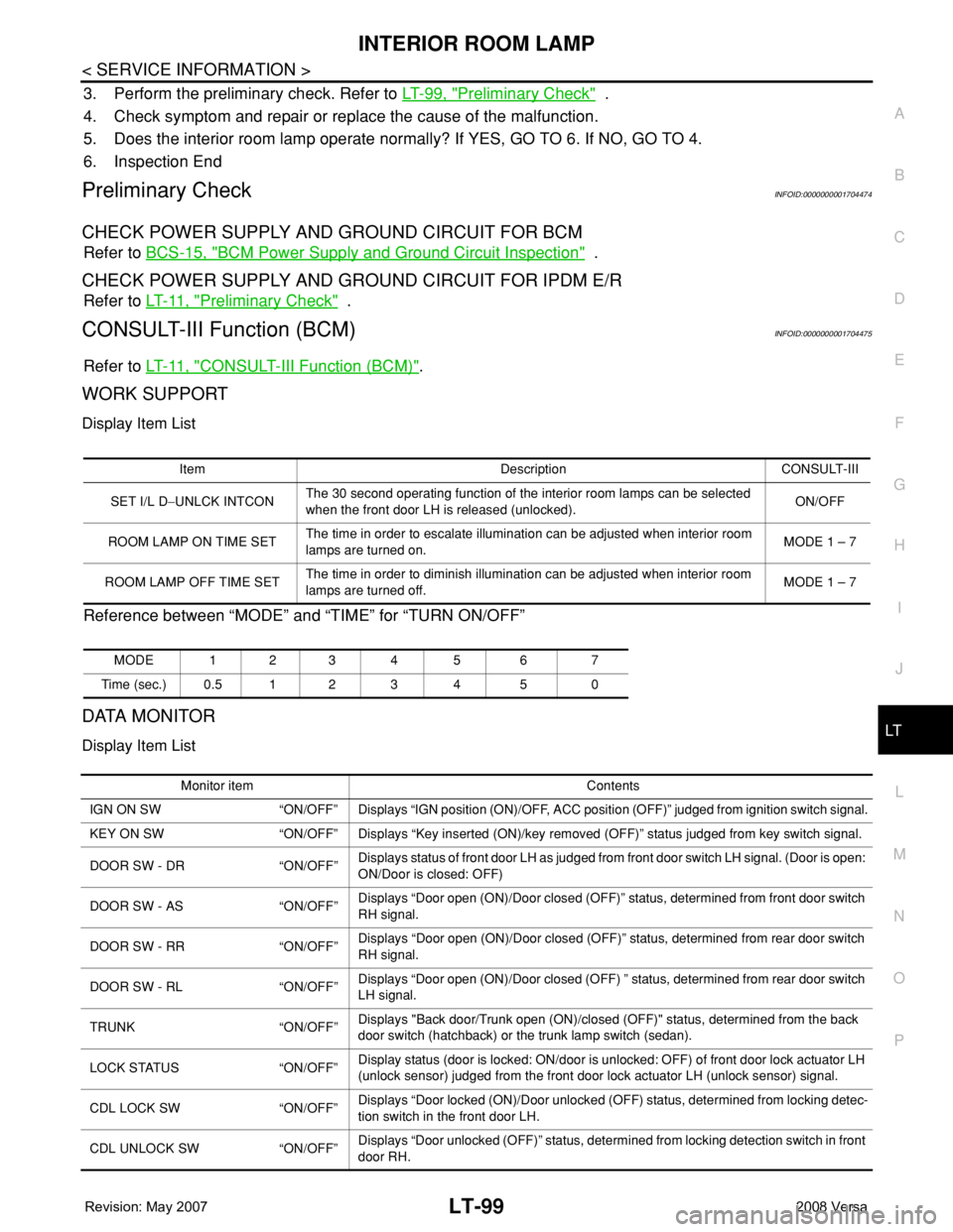
WORK SUPPORT
Display Item List
Reference between “MODE” and “TIME” for “TURN ON/OFF”
DATA MONITOR
Display Item List
Item Description CONSULT-III
SET I/L D−UNLCK INTCONThe 30 second operating function of the interior room lamps can be selected
when the front door LH is released (unlocked). ON/OFF
ROOM LAMP ON TIME SETThe time in order to escalate illumination can be adjusted when interior room
lamps are turned on.MODE 1 – 7
ROOM LAMP OFF TIME SETThe time in order to diminish illumination can be adjusted when interior room
lamps are turned off.MODE 1 – 7
MODE 123 4 5 6 7
Time (sec.) 0.5 1 2 3 4 5 0
Monitor item Contents
IGN ON SW “ON/OFF” Displays “IGN position (ON)/OFF, ACC position (OFF)” judged from ignition switch signal.
KEY ON SW “ON/OFF” Displays “Key inserted (ON)/key removed (OFF)” status judged from key switch signal.
DOOR SW - DR “ON/OFF”Displays status of front door LH as judged from front door switch LH signal. (Door is open:
ON/Door is closed: OFF)
DOOR SW - AS “ON/OFF”Displays “Door open (ON)/Door closed (OFF)” status, determined from front door switch
RH signal.
DOOR SW - RR “ON/OFF”Displays “Door open (ON)/Door closed (OFF)” status, determined from rear door switch
RH signal.
DOOR SW - RL “ON/OFF”Displays “Door open (ON)/Door closed (OFF) ” status, determined from rear door switch
LH signal.
TRUNK “ON/OFF”Displays "Back door/Trunk open (ON)/closed (OFF)" status, determined from the back
door switch (hatchback) or the trunk lamp switch (sedan).
LOCK STATUS “ON/OFF”Display status (door is locked: ON/door is unlocked: OFF) of front door lock actuator LH
(unlock sensor) judged from the front door lock actuator LH (unlock sensor) signal.
CDL LOCK SW “ON/OFF”Displays “Door locked (ON)/Door unlocked (OFF) status, determined from locking detec-
tion switch in the front door LH.
CDL UNLOCK SW “ON/OFF”Displays “Door unlocked (OFF)” status, determined from locking detection switch in front
door RH.
Page 2237 of 2771
LT-100
< SERVICE INFORMATION >
INTERIOR ROOM LAMP
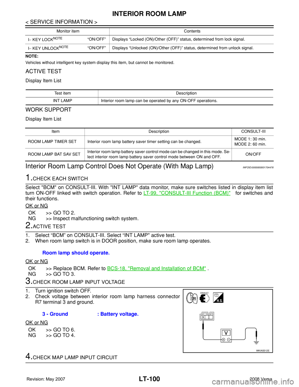
NOTE:
Vehicles without intelligent key system display this item, but cannot be monitored.
ACTIVE TEST
Display Item List
WORK SUPPORT
Display Item List
Interior Room Lamp Control Does Not Operate (With Map Lamp)INFOID:0000000001704476
1.CHECK EACH SWITCH
Select "BCM" on CONSULT-III. With "INT LAMP" data monitor, make sure switches listed in display item list
turn ON-OFF linked with switch operation. Refer to LT-99, "
CONSULT-III Function (BCM)" for switches and
their functions.
OK or NG
OK >> GO TO 2.
NG >> Inspect malfunctioning switch system.
2.ACTIVE TEST
1. Select “BCM” on CONSULT-III. Select “INT LAMP" active test.
2. When room lamp switch is in DOOR position, make sure room lamp operates.
OK or NG
OK >> Replace BCM. Refer to BCS-18, "Removal and Installation of BCM" .
NG >> GO TO 3.
3.CHECK ROOM LAMP INPUT VOLTAGE
1. Turn ignition switch OFF.
2. Check voltage between interior room lamp harness connector
R7 terminal 3 and ground.
OK or NG
OK >> GO TO 6.
NG >> GO TO 4.
4.CHECK MAP LAMP INPUT CIRCUIT
I− KEY LOCKNOTE“ON/OFF” Displays “Locked (ON)/Other (OFF)” status, determined from lock signal.
I− KEY UNLOCK
NOTE“ON/OFF” Displays “Unlocked (ON)/Other (OFF)” status, determined from unlock signal. Monitor item Contents
Test item Description
INT LAMP Interior room lamp can be operated by any ON-OFF operations.
Item Description CONSULT-III
ROOM LAMP TIMER SET Interior room lamp battery saver timer setting can be changed.MODE 1: 30 min.
MODE 2: 60 min.
ROOM LAMP BAT SAV SETInterior room lamp battery saver control mode can be changed in this mode. Se-
lect interior room lamp battery saver control mode between ON and OFF.ON/OFF
Room lamp should operate.
3 - Ground : Battery voltage.
WKIA5512E
Page 2239 of 2771
LT-102
< SERVICE INFORMATION >
INTERIOR ROOM LAMP
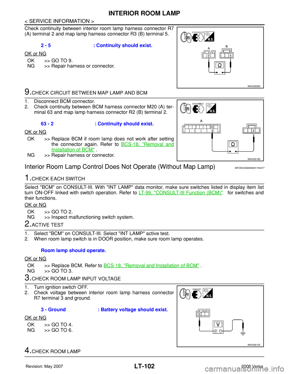
Check continuity between interior room lamp harness connector R7
(A) terminal 2 and map lamp harness connector R3 (B) terminal 5.
OK or NG
OK >> GO TO 9.
NG >> Repair harness or connector.
9.CHECK CIRCUIT BETWEEN MAP LAMP AND BCM
1. Disconnect BCM connector.
2. Check continuity between BCM harness connector M20 (A) ter-
minal 63 and map lamp harness connector R2 (B) terminal 2.
OK or NG
OK >> Replace BCM if room lamp does not work after setting
the connector again. Refer to BCS-18, "
Removal and
Installation of BCM" .
NG >> Repair harness or connector.
Interior Room Lamp Control Does Not Operate (Without Map Lamp)INFOID:0000000001704477
1.CHECK EACH SWITCH
Select "BCM" on CONSULT-III. With "INT LAMP" data monitor, make sure switches listed in display item list
turn ON-OFF linked with switch operation. Refer to LT-99, "
CONSULT-III Function (BCM)" for switches and
their functions.
OK or NG
OK >> GO TO 2.
NG >> Inspect malfunctioning switch system.
2.ACTIVE TEST
1. Select "BCM" on CONSULT-III. Select "INT LAMP" active test.
2. When room lamp switch is in DOOR position, make sure room lamp operates.
OK or NG
OK >> Replace BCM. Refer to BCS-18, "Removal and Installation of BCM" .
NG >> GO TO 3.
3.CHECK ROOM LAMP INPUT VOLTAGE
1. Turn ignition switch OFF.
2. Check voltage between interior room lamp harness connector
R7 terminal 3 and ground.
OK or NG
OK >> GO TO 4.
NG >> GO TO 6.
4.CHECK ROOM LAMP 2 - 5 : Continuity should exist.
WKIA5556E
63 - 2 : Continuity should exist.
WKIA5518E
Room lamp should operate.
3 - Ground : Battery voltage should exist.
WKIA5610E