2008 NISSAN LATIO display
[x] Cancel search: displayPage 1521 of 2771
DTC P1574 ASCD VEHICLE SPEED SENSOR
EC-447
< SERVICE INFORMATION >
C
D
E
F
G
H
I
J
K
L
MA
EC
N
P O
DTC P1574 ASCD VEHICLE SPEED SENSOR
Component DescriptionINFOID:0000000001702965
The ECM receives two vehicle speed sensor signals via CAN communication line. One is sent from combina-
tion meter, and the other is from TCM (Transmission control module). The ECM uses these signals for ASCD
control. Refer to EC-28
for ASCD functions.
On Board Diagnosis LogicINFOID:0000000001702966
This self-diagnosis has the one trip detection logic.
The MIL will not light up for this diagnosis.
NOTE:
•If DTC P1574 is displayed with DTC U1000, U1001, first perform the trouble diagnosis for DTC U1000,
U1001. Refer to EC-143
.
•If DTC P1574 is displayed with DTC U1010, first perform the trouble diagnosis for DTC U1010. Refer
to EC-145
.
•If DTC P1574 is displayed with DTC P0500, first perform the trouble diagnosis for DTC P0500. Refer
to EC-391
.
•If DTC P1574 is displayed with DTC P0605, first perform the trouble diagnosis for DTC P0605. Refer
to EC-397
.
DTC Confirmation ProcedureINFOID:0000000001702967
CAUTION:
Always drive vehicle at a safe speed.
NOTE:
If DTC Confirmation Procedure has been previously conducted, always turn ignition switch OFF and wait at
least 10 seconds before conducting the next test.
TESTING CONDITION:
Step 3 may be conducted with the drive wheels lifted in the shop or by driving the vehicle. If a road test
is expected to be easier, it is unnecessary to lift the vehicle.
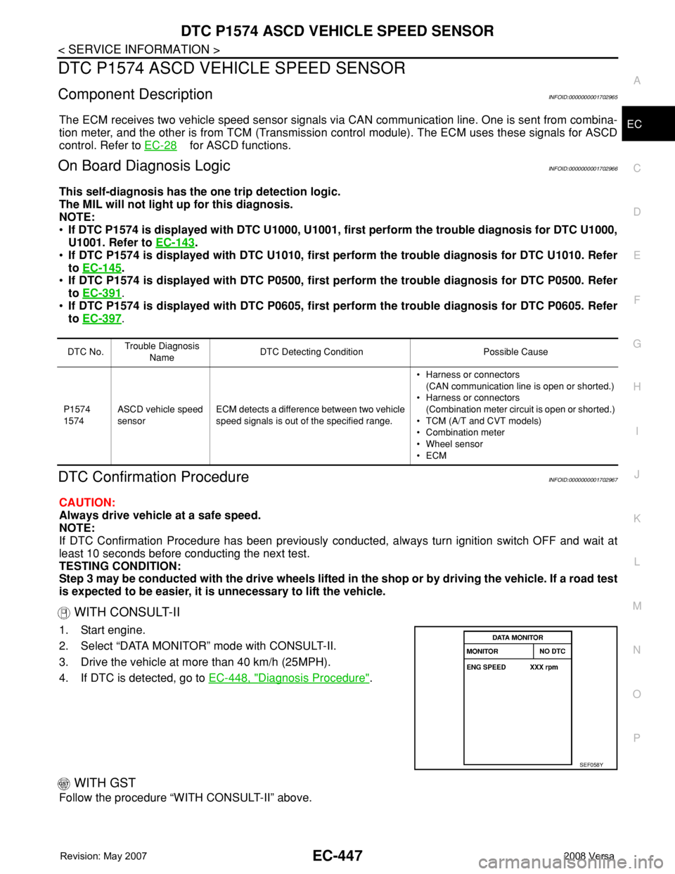
WITH CONSULT-II
1. Start engine.
2. Select “DATA MONITOR” mode with CONSULT-II.
3. Drive the vehicle at more than 40 km/h (25MPH).
4. If DTC is detected, go to EC-448, "
Diagnosis Procedure".
WITH GST
Follow the procedure “WITH CONSULT-II” above.
DTC No.Trouble Diagnosis
NameDTC Detecting Condition Possible Cause
P1574
1574ASCD vehicle speed
sensorECM detects a difference between two vehicle
speed signals is out of the specified range.• Harness or connectors
(CAN communication line is open or shorted.)
• Harness or connectors
(Combination meter circuit is open or shorted.)
• TCM (A/T and CVT models)
• Combination meter
• Wheel sensor
•ECM
SEF058Y
Page 1523 of 2771
DTC P1715 INPUT SPEED SENSOR (TURBINE REVOLUTION SENSOR)
EC-449
< SERVICE INFORMATION >
C
D
E
F
G
H
I
J
K
L
MA
EC
N
P O
DTC P1715 INPUT SPEED SENSOR (TURBINE REVOLUTION SENSOR)
DescriptionINFOID:0000000001702969
ECM receives turbine revolution sensor signal from TCM through CAN communication line. ECM uses this
signal for engine control.
CONSULT-II Reference Value in Data Monitor ModeINFOID:0000000001702970
Specification data are reference values.
On Board Diagnosis LogicINFOID:0000000001702971
NOTE:
•If DTC P1715 is displayed with DTC U1000, U1001 first perform the trouble diagnosis for DTC U1000,
U1001. Refer to EC-143
.
•If DTC P1715 is displayed with DTC U1010, first perform the trouble diagnosis for DTC U1010. Refer
to EC-145
.
•If DTC P1715 is displayed with DTC P0335, first perform the trouble diagnosis for DTC P0335. Refer
to EC-295
.
•If DTC P1715 is displayed with DTC P0340 first perform the trouble diagnosis for DTC P0340.
Refer to EC-302
.
•If DTC P1715 is displayed with DTC P0605, first perform the trouble diagnosis for DTC P0605. Refer
to EC-397
.
The MIL will not lights up for this diagnosis.
Diagnosis ProcedureINFOID:0000000001702972
1.CHECK DTC WITH TCM
Check DTC with TCM. Refer to AT- 3 6
.
OK or NG
OK >> GO TO 2.
NG >> Perform trouble shooting relevant to DTC indicated.
2.REPLACE TCM
Replace TCM. Refer to AT- 3 9
.
>>INSPECTION END
MONITOR ITEM CONDITION SPECIFICATION
I/P PULLY SPD • Vehicle speed: More than 20 km/h (12MPH)Almost the same speed as the
tachometer indication
DTC No. Trouble diagnosis name DTC detecting condition Possible cause
P1715
1715Input speed sensor
(Turbine revolution sen-
sor)
(TCM output)Turbine revolution sensor signal is differ-
ent from the theoretical value calculated
by ECM from revolution sensor signal and
engine rpm signal.• Harness or connectors
(CAN communication line is open or shorted)
• Harness or connectors
(Turbine revolution sensor circuit is open or
shorted)
•TCM
Page 1524 of 2771
EC-450
< SERVICE INFORMATION >
DTC P1715 INPUT SPEED SENSOR (PRIMARY SPEED SENSOR)
DTC P1715 INPUT SPEED SENSOR (PRIMARY SPEED SENSOR)
DescriptionINFOID:0000000001702973
ECM receives primary speed sensor signal from TCM through CAN communication line.
CONSULT-II Reference Value in Data Monitor ModeINFOID:0000000001702974
Specification data are reference values.
On Board Diagnosis LogicINFOID:0000000001702975
NOTE:
•If DTC P1715 is displayed with DTC U1000 or U1001 first perform the trouble diagnosis for DTC
U1000, U1001. Refer to EC-143
.
•If DTC P1715 is displayed with DTC U1010, first perform the trouble diagnosis for DTC U1010. Refer
to EC-145
.
•If DTC P1715 is displayed with DTC P0335, first perform the trouble diagnosis for DTC P0335. Refer
to EC-295
.
•If DTC P1715 is displayed with DTC P0340 first perform the trouble diagnosis for DTC P0340.
Refer to EC-302
.
•If DTC P1715 is displayed with DTC P0605, first perform the trouble diagnosis for DTC P0605. Refer
to EC-397
.
The MIL will not light up for this diagnosis.
DTC Confirmation ProcedureINFOID:0000000001702976
CAUTION:
Always drive vehicle at a safe speed.
NOTE:
If DTC Confirmation Procedure has been previously conducted, always turn ignition switch OFF and wait at
least 10 seconds before conducting the next test.
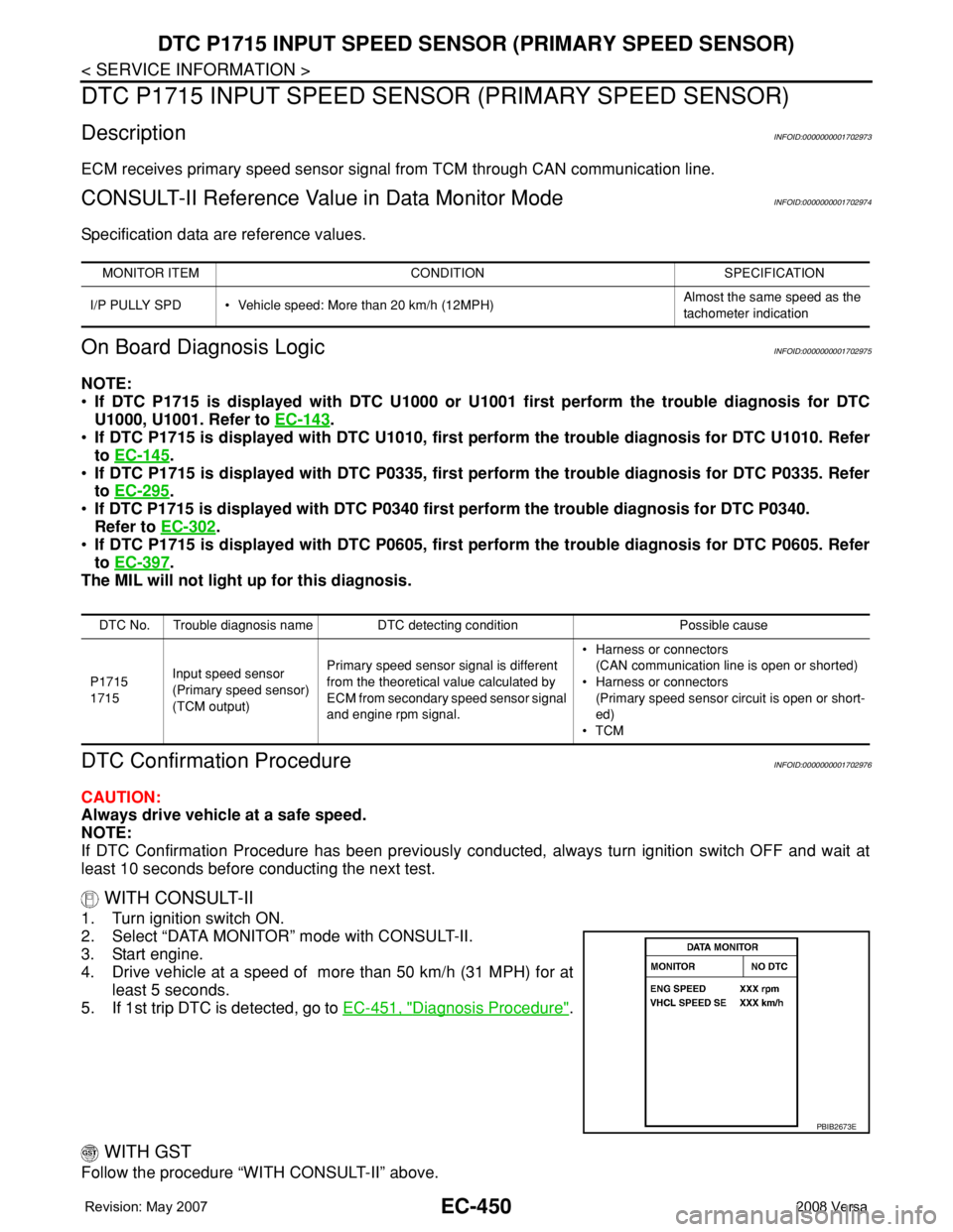
WITH CONSULT-II
1. Turn ignition switch ON.
2. Select “DATA MONITOR” mode with CONSULT-II.
3. Start engine.
4. Drive vehicle at a speed of more than 50 km/h (31 MPH) for at
least 5 seconds.
5. If 1st trip DTC is detected, go to EC-451, "
Diagnosis Procedure".
WITH GST
Follow the procedure “WITH CONSULT-II” above.
MONITOR ITEM CONDITION SPECIFICATION
I/P PULLY SPD • Vehicle speed: More than 20 km/h (12MPH)Almost the same speed as the
tachometer indication
DTC No. Trouble diagnosis name DTC detecting condition Possible cause
P1715
1715Input speed sensor
(Primary speed sensor)
(TCM output)Primary speed sensor signal is different
from the theoretical value calculated by
ECM from secondary speed sensor signal
and engine rpm signal.• Harness or connectors
(CAN communication line is open or shorted)
• Harness or connectors
(Primary speed sensor circuit is open or short-
ed)
•TCM
PBIB2673E
Page 1535 of 2771
DTC P2101 ELECTRIC THROTTLE CONTROL FUNCTION
EC-461
< SERVICE INFORMATION >
C
D
E
F
G
H
I
J
K
L
MA
EC
N
P O
DTC P2101 ELECTRIC THROTTLE CONTROL FUNCTION
DescriptionINFOID:0000000001702991
NOTE:
If DTC P2101 is displayed with DTC P2100 or P2119, first perform the trouble diagnosis for DTC P2100
or P2119. Refer to EC-456
or EC-472.
Electric throttle control actuator consists of throttle control motor, throttle position sensor, etc.
The throttle control motor is operated by the ECM and it opens and closes the throttle valve.
The current opening angle of the throttle valve is detected by the throttle position sensor and it provides feed-
back to the ECM to control the throttle control motor to make the throttle valve opening angle properly in
response to driving condition.
On Board Diagnosis LogicINFOID:0000000001702992
This self-diagnosis has the one trip detection logic.
FAIL-SAFE MODE
When the malfunction is detected, the ECM enters fail-safe mode and the MIL lights up.
DTC Confirmation ProcedureINFOID:0000000001702993
NOTE:
If DTC Confirmation Procedure has been previously conducted, always turn ignition switch OFF and wait at
least 10 seconds before conducting the next test.
TESTING CONDITION:
Before performing the following procedure, confirm that battery voltage is more than 11V when engine
is running.
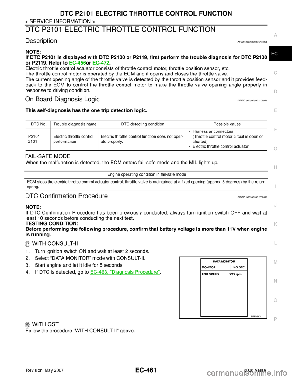
WITH CONSULT-II
1. Turn ignition switch ON and wait at least 2 seconds.
2. Select “DATA MONITOR” mode with CONSULT-II.
3. Start engine and let it idle for 5 seconds.
4. If DTC is detected, go to EC-463, "
Diagnosis Procedure".
WITH GST
Follow the procedure “WITH CONSULT-II” above.
DTC No. Trouble diagnosis name DTC detecting condition Possible cause
P2101
2101Electric throttle control
performanceElectric throttle control function does not oper-
ate properly.• Harness or connectors
(Throttle control motor circuit is open or
shorted)
• Electric throttle control actuator
Engine operating condition in fail-safe mode
ECM stops the electric throttle control actuator control, throttle valve is maintained at a fixed opening (approx. 5 degrees) by the return
spring.
SEF058Y
Page 1548 of 2771
EC-474
< SERVICE INFORMATION >
DTC P2122, P2123 APP SENSOR
DTC P2122, P2123 APP SENSOR
Component DescriptionINFOID:0000000001703009
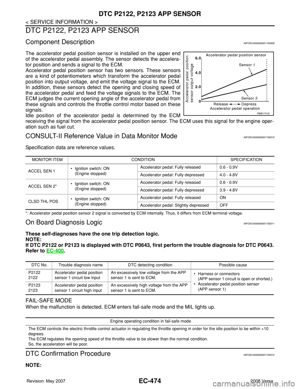
The accelerator pedal position sensor is installed on the upper end
of the accelerator pedal assembly. The sensor detects the accelera-
tor position and sends a signal to the ECM.
Accelerator pedal position sensor has two sensors. These sensors
are a kind of potentiometers which transform the accelerator pedal
position into output voltage, and emit the voltage signal to the ECM.
In addition, these sensors detect the opening and closing speed of
the accelerator pedal and feed the voltage signals to the ECM. The
ECM judges the current opening angle of the accelerator pedal from
these signals and controls the throttle control motor based on these
signals.
Idle position of the accelerator pedal is determined by the ECM
receiving the signal from the accelerator pedal position sensor. The ECM uses this signal for the engine oper-
ation such as fuel cut.
CONSULT-II Reference Value in Data Monitor ModeINFOID:0000000001703010
Specification data are reference values.
*: Accelerator pedal position sensor 2 signal is converted by ECM internally. Thus, it differs from ECM terminal voltage.
On Board Diagnosis LogicINFOID:0000000001703011
These self-diagnoses have the one trip detection logic.
NOTE:
If DTC P2122 or P2123 is displayed with DTC P0643, first perform the trouble diagnosis for DTC P0643.
Refer to EC-400
.
FAIL-SAFE MODE
When the malfunction is detected, ECM enters fail-safe mode and the MIL lights up.
DTC Confirmation ProcedureINFOID:0000000001703012
NOTE:
PBIB1741E
MONITOR ITEM CONDITION SPECIFICATION
ACCEL SEN 1• Ignition switch: ON
(Engine stopped)Accelerator pedal: Fully released 0.6 - 0.9V
Accelerator pedal: Fully depressed 4.0 - 4.8V
ACCEL SEN 2*• Ignition switch: ON
(Engine stopped)Accelerator pedal: Fully released 0.6 - 0.9V
Accelerator pedal: Fully depressed 3.9 - 4.8V
CLSD THL POS• Ignition switch: ON
(Engine stopped)Accelerator pedal: Fully released ON
Accelerator pedal: Slightly depressed OFF
DTC No. Trouble diagnosis name DTC detecting condition Possible cause
P2122
2122Accelerator pedal position
sensor 1 circuit low inputAn excessively low voltage from the APP
sensor 1 is sent to ECM.• Harness or connectors
(APP sensor 1 circuit is open or shorted.)
• Accelerator pedal position sensor
(APP sensor 1) P2123
2123Accelerator pedal position
sensor 1 circuit high inputAn excessively high voltage from the APP
sensor 1 is sent to ECM.
Engine operating condition in fail-safe mode
The ECM controls the electric throttle control actuator in regulating the throttle opening in order for the idle position to be within +10
degrees.
The ECM regulates the opening speed of the throttle valve to be slower than the normal condition.
So, the acceleration will be poor.
Page 1561 of 2771
DTC P2135 TP SENSOR
EC-487
< SERVICE INFORMATION >
C
D
E
F
G
H
I
J
K
L
MA
EC
N
P O
DTC P2135 TP SENSOR
Component DescriptionINFOID:0000000001703025
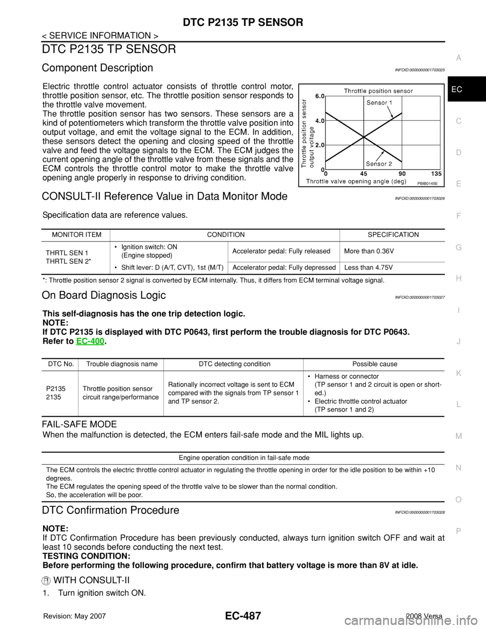
Electric throttle control actuator consists of throttle control motor,
throttle position sensor, etc. The throttle position sensor responds to
the throttle valve movement.
The throttle position sensor has two sensors. These sensors are a
kind of potentiometers which transform the throttle valve position into
output voltage, and emit the voltage signal to the ECM. In addition,
these sensors detect the opening and closing speed of the throttle
valve and feed the voltage signals to the ECM. The ECM judges the
current opening angle of the throttle valve from these signals and the
ECM controls the throttle control motor to make the throttle valve
opening angle properly in response to driving condition.
CONSULT-II Reference Value in Data Monitor ModeINFOID:0000000001703026
Specification data are reference values.
*: Throttle position sensor 2 signal is converted by ECM internally. Thus, it differs from ECM terminal voltage signal.
On Board Diagnosis LogicINFOID:0000000001703027
This self-diagnosis has the one trip detection logic.
NOTE:
If DTC P2135 is displayed with DTC P0643, first perform the trouble diagnosis for DTC P0643.
Refer to EC-400
.
FAIL-SAFE MODE
When the malfunction is detected, the ECM enters fail-safe mode and the MIL lights up.
DTC Confirmation ProcedureINFOID:0000000001703028
NOTE:
If DTC Confirmation Procedure has been previously conducted, always turn ignition switch OFF and wait at
least 10 seconds before conducting the next test.
TESTING CONDITION:
Before performing the following procedure, confirm that battery voltage is more than 8V at idle.
WITH CONSULT-II
1. Turn ignition switch ON.
PBIB0145E
MONITOR ITEM CONDITION SPECIFICATION
THRTL SEN 1
THRTL SEN 2*• Ignition switch: ON
(Engine stopped)Accelerator pedal: Fully released More than 0.36V
• Shift lever: D (A/T, CVT), 1st (M/T) Accelerator pedal: Fully depressed Less than 4.75V
DTC No. Trouble diagnosis name DTC detecting condition Possible cause
P2135
2135Throttle position sensor
circuit range/performanceRationally incorrect voltage is sent to ECM
compared with the signals from TP sensor 1
and TP sensor 2.• Harness or connector
(TP sensor 1 and 2 circuit is open or short-
ed.)
• Electric throttle control actuator
(TP sensor 1 and 2)
Engine operation condition in fail-safe mode
The ECM controls the electric throttle control actuator in regulating the throttle opening in order for the idle position to be within +10
degrees.
The ECM regulates the opening speed of the throttle valve to be slower than the normal condition.
So, the acceleration will be poor.
Page 1567 of 2771
DTC P2138 APP SENSOR
EC-493
< SERVICE INFORMATION >
C
D
E
F
G
H
I
J
K
L
MA
EC
N
P O
DTC P2138 APP SENSOR
Component DescriptionINFOID:0000000001703033
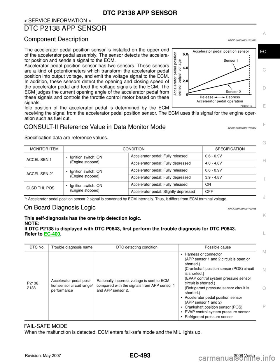
The accelerator pedal position sensor is installed on the upper end
of the accelerator pedal assembly. The sensor detects the accelera-
tor position and sends a signal to the ECM.
Accelerator pedal position sensor has two sensors. These sensors
are a kind of potentiometers which transform the accelerator pedal
position into output voltage, and emit the voltage signal to the ECM.
In addition, these sensors detect the opening and closing speed of
the accelerator pedal and feed the voltage signals to the ECM. The
ECM judges the current opening angle of the accelerator pedal from
these signals and controls the throttle control motor based on these
signals.
Idle position of the accelerator pedal is determined by the ECM
receiving the signal from the accelerator pedal position sensor. The ECM uses this signal for the engine oper-
ation such as fuel cut.
CONSULT-II Reference Value in Data Monitor ModeINFOID:0000000001703034
Specification data are reference values.
*: Accelerator pedal position sensor 2 signal is converted by ECM internally. Thus, it differs from ECM terminal voltage.
On Board Diagnosis LogicINFOID:0000000001703035
This self-diagnosis has the one trip detection logic.
NOTE:
If DTC P2138 is displayed with DTC P0643, first perform the trouble diagnosis for DTC P0643.
Refer to EC-400
.
FAIL-SAFE MODE
When the malfunction is detected, ECM enters fail-safe mode and the MIL lights up.
PBIB1741E
MONITOR ITEM CONDITION SPECIFICATION
ACCEL SEN 1• Ignition switch: ON
(Engine stopped)Accelerator pedal: Fully released 0.6 - 0.9V
Accelerator pedal: Fully depressed 4.0 - 4.8V
ACCEL SEN 2*• Ignition switch: ON
(Engine stopped)Accelerator pedal: Fully released 0.6 - 0.9V
Accelerator pedal: Fully depressed 3.9 - 4.8V
CLSD THL POS• Ignition switch: ON
(Engine stopped)Accelerator pedal: Fully released ON
Accelerator pedal: Slightly depressed OFF
DTC No. Trouble diagnosis name DTC detecting condition Possible cause
P2138
2138Accelerator pedal posi-
tion sensor circuit range/
performanceRationally incorrect voltage is sent to ECM
compared with the signals from APP sensor 1
and APP sensor 2.• Harness or connector
(APP sensor 1 and 2 circuit is open or
shorted.)
[Crankshaft position sensor (POS) circuit
is shorted.]
(EVAP control system pressure sensor
circuit is shorted.)
(Refrigerant pressure sensor circuit is
shorted.)
• Accelerator pedal position sensor
(APP sensor 1 and 2)
• Crankshaft position sensor (POS)
• EVAP control system pressure sensor
• Refrigerant pressure sensor
Page 1578 of 2771
EC-504
< SERVICE INFORMATION >
DTC P2A00 A/F SENSOR 1
3.CHECK FOR INTAKE AIR LEAK
1. Start engine and run it at idle.
2. Listen for an intake air leak after the mass air flow sensor.
OK or NG
OK >> GO TO 4.
NG >> Repair or replace.
4.CLEAR THE SELF-LEARNING DATA
With CONSULT-II
1. Start engine and warm it up to normal operating temperature.
2. Select “SELF-LEARNING CONT” in “WORK SUPPORT” mode with CONSULT-II.
3. Clear the self-learning control coefficient by touching “CLEAR”.
4. Run engine for at least 10 minutes at idle speed.
Is the 1st trip DTC P0171 and P0172 detected?
Is it difficult to start engine?
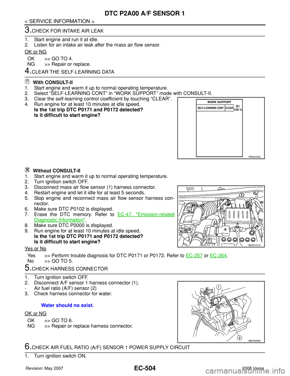
Without CONSULT-II
1. Start engine and warm it up to normal operating temperature.
2. Turn ignition switch OFF.
3. Disconnect mass air flow sensor (1) harness connector.
4. Restart engine and let it idle for at least 5 seconds.
5. Stop engine and reconnect mass air flow sensor harness con-
nector.
6. Make sure DTC P0102 is displayed.
7. Erase the DTC memory. Refer to EC-47, "
Emission-related
Diagnostic Information".
8. Make sure DTC P0000 is displayed.
9. Run engine for at least 10 minutes at idle speed.
Is the 1st trip DTC P0171 and P0172 detected?
Is it difficult to start engine?
Ye s o r N o
Yes >> Perform trouble diagnosis for DTC P0171 or P0172. Refer to EC-257 or EC-264.
No >> GO TO 5.
5.CHECK HARNESS CONNECTOR
1. Turn ignition switch OFF.
2. Disconnect A/F sensor 1 harness connector (1).
- Air fuel ratio (A/F) sensor (2)
3. Check harness connector for water.
OK or NG
OK >> GO TO 6.
NG >> Repair or replace harness connector.
6.CHECK AIR FUEL RATIO (A/F) SENSOR 1 POWER SUPPLY CIRCUIT
1. Turn ignition switch ON.
PBIB2035E
BBIA0701E
Water should no exist.
BBIA0699E