2008 NISSAN LATIO display
[x] Cancel search: displayPage 2346 of 2771
MTC-8
< SERVICE INFORMATION >
PRECAUTIONS
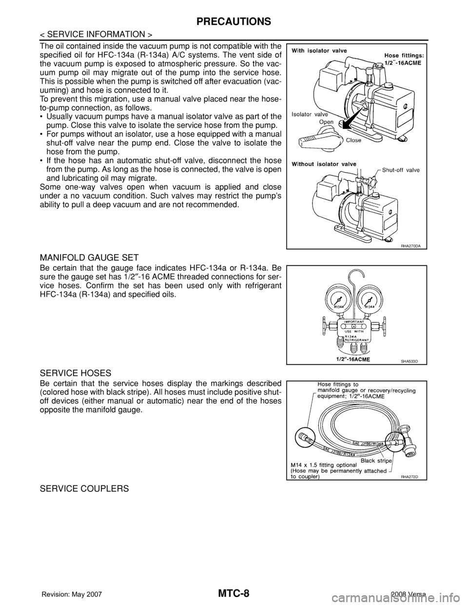
The oil contained inside the vacuum pump is not compatible with the
specified oil for HFC-134a (R-134a) A/C systems. The vent side of
the vacuum pump is exposed to atmospheric pressure. So the vac-
uum pump oil may migrate out of the pump into the service hose.
This is possible when the pump is switched off after evacuation (vac-
uuming) and hose is connected to it.
To prevent this migration, use a manual valve placed near the hose-
to-pump connection, as follows.
• Usually vacuum pumps have a manual isolator valve as part of the
pump. Close this valve to isolate the service hose from the pump.
• For pumps without an isolator, use a hose equipped with a manual
shut-off valve near the pump end. Close the valve to isolate the
hose from the pump.
• If the hose has an automatic shut-off valve, disconnect the hose
from the pump. As long as the hose is connected, the valve is open
and lubricating oil may migrate.
Some one-way valves open when vacuum is applied and close
under a no vacuum condition. Such valves may restrict the pump’s
ability to pull a deep vacuum and are not recommended.
MANIFOLD GAUGE SET
Be certain that the gauge face indicates HFC-134a or R-134a. Be
sure the gauge set has 1/2″-16 ACME threaded connections for ser-
vice hoses. Confirm the set has been used only with refrigerant
HFC-134a (R-134a) and specified oils.
SERVICE HOSES
Be certain that the service hoses display the markings described
(colored hose with black stripe). All hoses must include positive shut-
off devices (either manual or automatic) near the end of the hoses
opposite the manifold gauge.
SERVICE COUPLERS
RHA270DA
SHA533D
RHA272D
Page 2355 of 2771
OIL
MTC-17
< SERVICE INFORMATION >
C
D
E
F
G
H
I
K
L
MA
B
MTC
N
O
P
*1: If refrigerant leak is small, no addition of oil is needed.
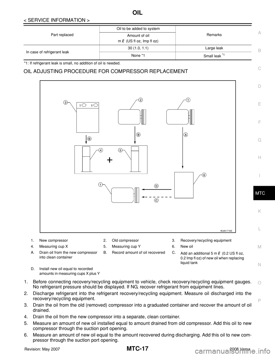
OIL ADJUSTING PROCEDURE FOR COMPRESSOR REPLACEMENT
1. Before connecting recovery/recycling equipment to vehicle, check recovery/recycling equipment gauges.
No refrigerant pressure should be displayed. If NG, recover refrigerant from equipment lines.
2. Discharge refrigerant into the refrigerant recovery/recycling equipment. Measure oil discharged into the
recovery/recycling equipment.
3. Drain the oil from the old (removed) compressor into a graduated container and recover the amount of oil
drained.
4. Drain the oil from the new compressor into a separate, clean container.
5. Measure an amount of new oil installed equal to amount drained from old compressor. Add this oil to new
compressor through the suction port opening.
6. Measure an amount of new oil equal to the amount recovered during discharging. Add this oil to new com-
pressor through the suction port opening.
In case of refrigerant leak30 (1.0, 1.1) Large leak
None *1
Small leak *1
Part replacedOil to be added to system
Remarks
Amount of oil
m (US fl oz, Imp fl oz)
1. New compressor 2. Old compressor 3. Recovery/recycling equipment
4. Measuring cup X 5. Measuring cup Y 6. New oil
A. Drain oil from the new compressor
into clean containerB. Record amount of oil recovered C.
Add an additional 5 m (0.2 US fl oz,
0.2 Imp fl oz) of new oil when replacing
liquid tank
D. Install new oil equal to recorded
amounts in measuring cups X plus Y
WJIA1716E
Page 2360 of 2771
MTC-22
< SERVICE INFORMATION >
TROUBLE DIAGNOSIS
TROUBLE DIAGNOSIS
CONSULT-III Function (BCM)INFOID:0000000001704294
CONSULT-III can display each diagnostic item using the diagnostic test modes shown following.
DATA MONITOR
Display Item List
How to Perform Trouble Diagnosis for Quick and Accurate RepairINFOID:0000000001704295
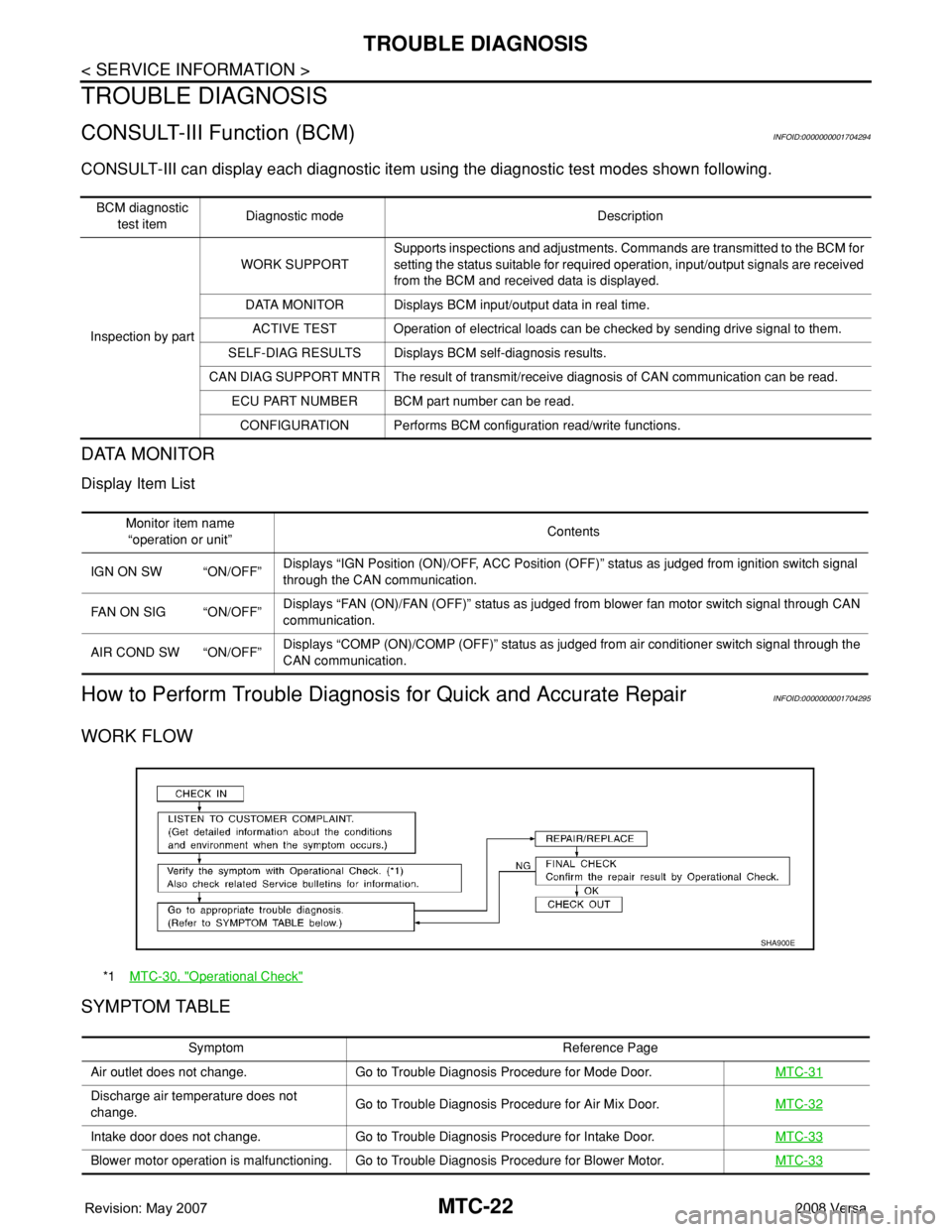
WORK FLOW
SYMPTOM TABLE
BCM diagnostic
test itemDiagnostic mode Description
Inspection by partWORK SUPPORTSupports inspections and adjustments. Commands are transmitted to the BCM for
setting the status suitable for required operation, input/output signals are received
from the BCM and received data is displayed.
DATA MONITOR Displays BCM input/output data in real time.
ACTIVE TEST Operation of electrical loads can be checked by sending drive signal to them.
SELF-DIAG RESULTS Displays BCM self-diagnosis results.
CAN DIAG SUPPORT MNTR The result of transmit/receive diagnosis of CAN communication can be read.
ECU PART NUMBER BCM part number can be read.
CONFIGURATION Performs BCM configuration read/write functions.
Monitor item name
“operation or unit”Contents
IGN ON SW “ON/OFF”Displays “IGN Position (ON)/OFF, ACC Position (OFF)” status as judged from ignition switch signal
through the CAN communication.
FAN ON SIG “ON/OFF”Displays “FAN (ON)/FAN (OFF)” status as judged from blower fan motor switch signal through CAN
communication.
AIR COND SW “ON/OFF”Displays “COMP (ON)/COMP (OFF)” status as judged from air conditioner switch signal through the
CAN communication.
*1MTC-30, "Operational Check"
SHA900E
Symptom Reference Page
Air outlet does not change. Go to Trouble Diagnosis Procedure for Mode Door.MTC-31
Discharge air temperature does not
change.Go to Trouble Diagnosis Procedure for Air Mix Door.MTC-32
Intake door does not change. Go to Trouble Diagnosis Procedure for Intake Door.MTC-33
Blower motor operation is malfunctioning. Go to Trouble Diagnosis Procedure for Blower Motor.MTC-33
Page 2425 of 2771
REFRIGERANT LINES
MTC-87
< SERVICE INFORMATION >
C
D
E
F
G
H
I
K
L
MA
B
MTC
N
O
P
Check all around the service valves. Ensure service valve caps are secured on the service valves (to
prevent leaks).
NOTE:
After removing A/C manifold gauge set from service valves, wipe any residue from valves to prevent any
false readings by leak detector.
• Cooling unit (Evaporator)
With engine OFF, turn blower fan on “High” for at least 15 seconds to dissipate any refrigerant trace in
the cooling unit. Wait a minimum of 10 minutes accumulation time (refer to the manufacturer’s recom-
mended procedure for actual wait time) before inserting the leak detector probe into the drain hose.
Keep the probe inserted for at least 10 seconds. Use caution not to contaminate the probe tip with water
or dirt that may be in the drain hose.
5. If a leak detector detects a leak, verify at least once by blowing compressed air into area of suspected
leak, then repeat check as outlined above.
6. Do not stop when one leak is found. Continue to check for additional leaks at all system components.
If no leaks are found, perform steps 7-10.
7. Start engine.
8. Set the heater A/C control as follows;
a. A/C switch: ON
b. Mode control dial position: VENT (Ventilation)
c. Intake door lever position: Recirculation
d. Max. cold temperature
e. Fan speed: High
9. Run engine at 1,500 rpm for at least 2 minutes.
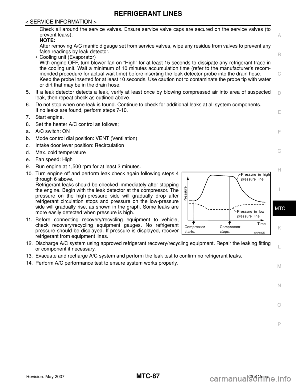
10. Turn engine off and perform leak check again following steps 4
through 6 above.
Refrigerant leaks should be checked immediately after stopping
the engine. Begin with the leak detector at the compressor. The
pressure on the high-pressure side will gradually drop after
refrigerant circulation stops and pressure on the low-pressure
side will gradually rise, as shown in the graph. Some leaks are
more easily detected when pressure is high.
11. Before connecting recovery/recycling equipment to vehicle,
check recovery/recycling equipment gauges. No refrigerant
pressure should be displayed. If pressure is displayed, recover
refrigerant from equipment lines.
12. Discharge A/C system using approved refrigerant recovery/recycling equipment. Repair the leaking fitting
or component if necessary.
13. Evacuate and recharge A/C system and perform the leak test to confirm no refrigerant leaks.
14. Perform A/C performance test to ensure system works properly.
SHA839E
Page 2450 of 2771
IPDM E/R (INTELLIGENT POWER DISTRIBUTION MODULE ENGINE ROOM)
PG-17
< SERVICE INFORMATION >
C
D
E
F
G
H
I
J
L
MA
B
PG
N
O
P
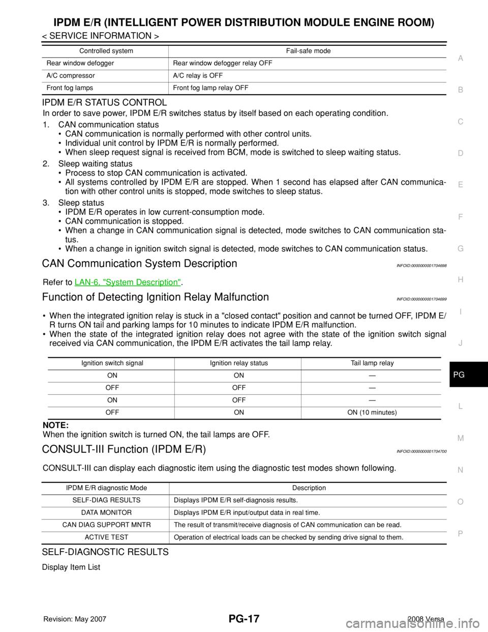
IPDM E/R STATUS CONTROL
In order to save power, IPDM E/R switches status by itself based on each operating condition.
1. CAN communication status
• CAN communication is normally performed with other control units.
• Individual unit control by IPDM E/R is normally performed.
• When sleep request signal is received from BCM, mode is switched to sleep waiting status.
2. Sleep waiting status
• Process to stop CAN communication is activated.
• All systems controlled by IPDM E/R are stopped. When 1 second has elapsed after CAN communica-
tion with other control units is stopped, mode switches to sleep status.
3. Sleep status
• IPDM E/R operates in low current-consumption mode.
• CAN communication is stopped.
• When a change in CAN communication signal is detected, mode switches to CAN communication sta-
tus.
• When a change in ignition switch signal is detected, mode switches to CAN communication status.
CAN Communication System DescriptionINFOID:0000000001704698
Refer to LAN-6, "System Description".
Function of Detecting Ignition Relay MalfunctionINFOID:0000000001704699
• When the integrated ignition relay is stuck in a "closed contact" position and cannot be turned OFF, IPDM E/
R turns ON tail and parking lamps for 10 minutes to indicate IPDM E/R malfunction.
• When the state of the integrated ignition relay does not agree with the state of the ignition switch signal
received via CAN communication, the IPDM E/R activates the tail lamp relay.
NOTE:
When the ignition switch is turned ON, the tail lamps are OFF.
CONSULT-III Function (IPDM E/R)INFOID:0000000001704700
CONSULT-III can display each diagnostic item using the diagnostic test modes shown following.
SELF-DIAGNOSTIC RESULTS
Display Item List
Rear window defogger Rear window defogger relay OFF
A/C compressor A/C relay is OFF
Front fog lamps Front fog lamp relay OFFControlled system Fail-safe mode
Ignition switch signal Ignition relay status Tail lamp relay
ON ON —
OFF OFF —
ON OFF —
OFF ON ON (10 minutes)
IPDM E/R diagnostic Mode Description
SELF-DIAG RESULTS Displays IPDM E/R self-diagnosis results.
DATA MONITOR Displays IPDM E/R input/output data in real time.
CAN DIAG SUPPORT MNTR The result of transmit/receive diagnosis of CAN communication can be read.
ACTIVE TEST Operation of electrical loads can be checked by sending drive signal to them.
Page 2451 of 2771

PG-18
< SERVICE INFORMATION >
IPDM E/R (INTELLIGENT POWER DISTRIBUTION MODULE ENGINE ROOM)
x: Applicable
NOTE:
The details for display of the period are as follows:
• CRNT: Error currently detected with IPDM E/R.
• PAST: Error detected in the past and placed in IPDM E/R memory.
DATA MONITOR
All Signals, Main Signals, Selection From Menu
Display itemsCONSULT-
III display
codeMalfunction detectionTIME
Possible causes
CRNT PAST
NO DTC IS DETECTED.
FURTHER TESTING
MAY BE REQUIRED.—————
CAN COMM CIRC U1000• If CAN communication reception/transmission
data has a malfunction, or if any of the control
units fail, data reception/transmission cannot be
confirmed.
• When the data in CAN communication is not re-
ceived before the specified time.XXAny of items listed
below have errors:
• TRANSMIT DIAG
•ECM
• BCM/SEC
IGN RELAY ON —When the ignition switch is not in the ON position,
the ignition relay in the IPDM E/R is ON.XX
IGN RELAY OFF —When the ignition switch is not in the ON position,
the ignition relay in the IPDM E/R is OFF.XX
EEPROM —Malfunction is detected with the integrated EEPROM
memory diagnosis.XX
Item nameCONSULT-III
screen display Display or unitMonitor item selection
Description
ALL
SIGNALSMAIN
SIGNALSSELECTION
FROM MENU
Motor fan requestMOTOR FAN
REQ1/2/3/4 X X X Signal status input from ECM
Compressor re-
questAC COMP REQ ON/OFF X X X Signal status input from ECM
Parking, license,
and tail lamp re-
questTAIL & CLR REQ ON/OFF X X X Signal status input from BCM
Headlamp low
beam requestHL LO REQ ON/OFF X X X Signal status input from BCM
Headlamp high
beam requestHL HI REQ ON/OFF X X X Signal status input from BCM
Front fog request FR FOG REQ ON/OFF X X X Signal status input from BCM
FR wiper request FR WIP REQ STOP/1LO/LO/HI X X X Signal status input from BCM
Wiper auto stopWIP AUTO
STOPACT P/STOP P X X X Output status of IPDM E/R
Wiper protection WIP PROT OFF/LS/HS/Block X X X Control status of IPDM E/R
Starter request ST RLY REQ ON/OFF X X Status of input signal (*1)
Ignition relay
statusIGN RLY ON/OFF X X XIgnition relay status monitored
with IPDM E/R
Rear defogger re-
questRR DEF REQ ON/OFF X X X Signal status input from BCM
Oil pressure
switchOIL P SW OPEN/CLOSE X XSignal status input from IPDM
E/R
Hood switch HOOD SW (*2) OFF X XSignal status input from IPDM
E/R
Page 2452 of 2771
IPDM E/R (INTELLIGENT POWER DISTRIBUTION MODULE ENGINE ROOM)
PG-19
< SERVICE INFORMATION >
C
D
E
F
G
H
I
J
L
MA
B
PG
N
O
P
*1 Perform monitoring of IPDM E/R data with the ignition switch ON. When the ignition switch is in ACC position, display may not be cor-
rect.
*2 This item is displayed, but does not function.
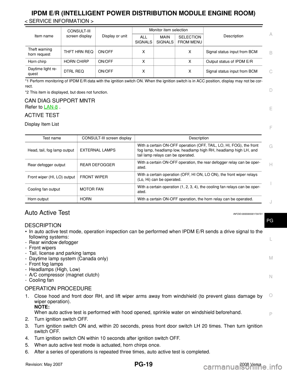
CAN DIAG SUPPORT MNTR
Refer to LAN-8 .
ACTIVE TEST
Display Item List
Auto Active TestINFOID:0000000001704701
DESCRIPTION
• In auto active test mode, operation inspection can be performed when IPDM E/R sends a drive signal to the
following systems:
- Rear window defogger
- Front wipers
- Tail, license and parking lamps
- Daytime lamp system (Canada only)
- Front fog lamps
- Headlamps (High, Low)
- A/C compressor (magnet clutch)
- Cooling fan
OPERATION PROCEDURE
1. Close hood and front door RH, and lift wiper arms away from windshield (to prevent glass damage by
wiper operation).
NOTE:
When auto active test is performed with hood opened, sprinkle water on windshield beforehand.
2. Turn ignition switch OFF.
3. Turn ignition switch ON and, within 20 seconds, press front door switch LH 20 times. Then turn ignition
switch OFF.
4. Turn ignition switch ON within 10 seconds after ignition switch OFF.
5. When auto active test mode is actuated, horn chirps once.
6. After a series of operations is repeated three times, auto active test is completed.
Theft warning
horn requestTHFT HRN REQ ON/OFF X X Signal status input from BCM
Horn chirp HORN CHIRP ON/OFF X X Output status of IPDM E/R
Daytime light re-
questDTRL REQ ON/OFF X X Signal status input from BCM Item nameCONSULT-III
screen display Display or unitMonitor item selection
Description
ALL
SIGNALSMAIN
SIGNALSSELECTION
FROM MENU
Test name CONSULT-III screen display Description
Head, tail, fog lamp output EXTERNAL LAMPSWith a certain ON-OFF operation (OFF, TAIL, LO, HI, FOG), the front
fog lamp, headlamp low, headlamp high RH, headlamp high LH, and
tail lamp relays can be operated.
Rear defogger output REAR DEFOGGERWith a certain ON-OFF operation, the rear defogger relay can be oper-
ated.
Front wiper (HI, LO) output FRONT WIPERWith a certain operation (OFF, HI ON, LO ON), the front wiper relays
(Lo, Hi) can be operated.
Cooling fan output MOTOR FANWith a certain operation (1, 2, 3, 4), the cooling fan relays can be oper-
ated.
Horn output HORN With a certain ON-OFF operation, the horn relay can be operated.
Page 2459 of 2771
PG-26
< SERVICE INFORMATION >
IPDM E/R (INTELLIGENT POWER DISTRIBUTION MODULE ENGINE ROOM)
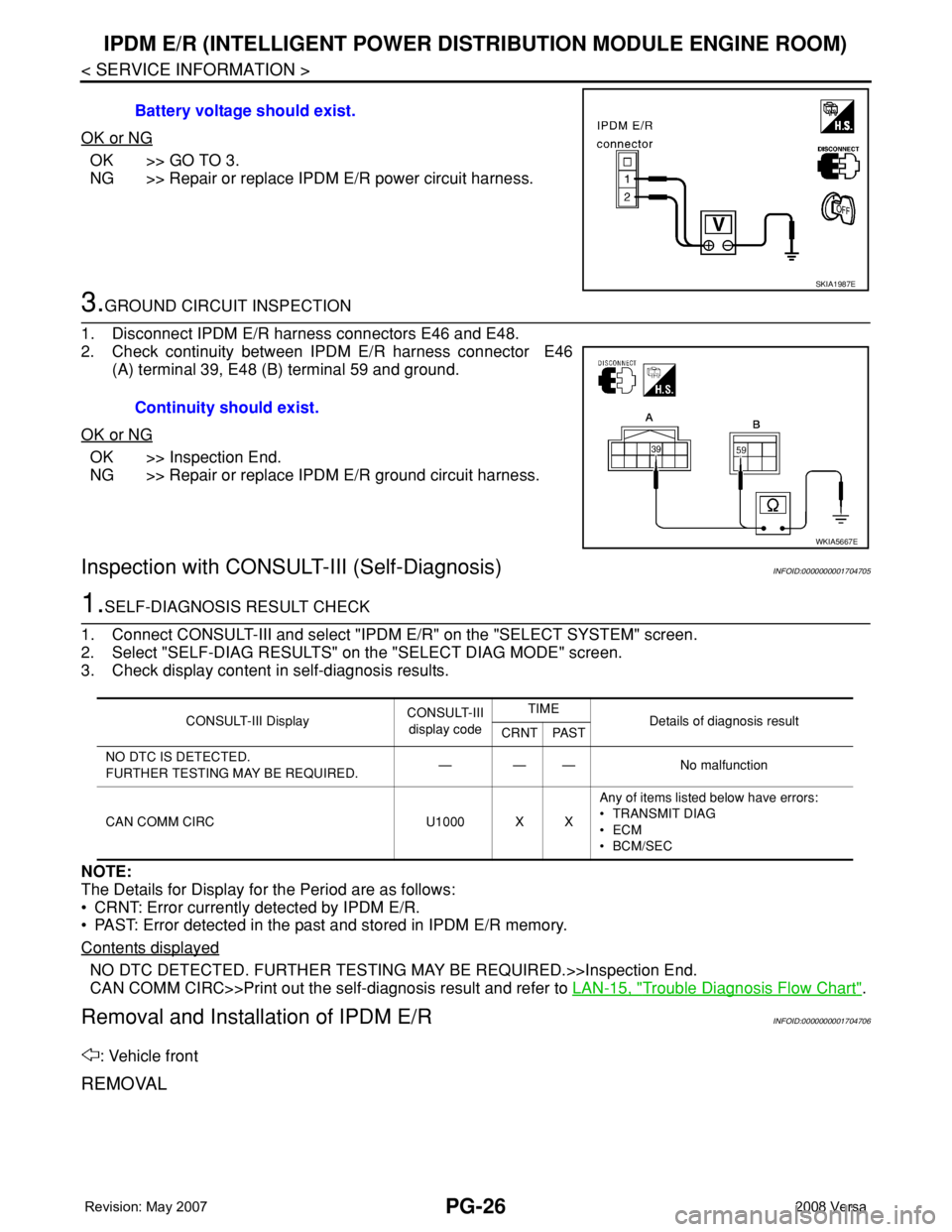
OK or NG
OK >> GO TO 3.
NG >> Repair or replace IPDM E/R power circuit harness.
3.GROUND CIRCUIT INSPECTION
1. Disconnect IPDM E/R harness connectors E46 and E48.
2. Check continuity between IPDM E/R harness connector E46
(A) terminal 39, E48 (B) terminal 59 and ground.
OK or NG
OK >> Inspection End.
NG >> Repair or replace IPDM E/R ground circuit harness.
Inspection with CONSULT-III (Self-Diagnosis)INFOID:0000000001704705
1.SELF-DIAGNOSIS RESULT CHECK
1. Connect CONSULT-III and select "IPDM E/R" on the "SELECT SYSTEM" screen.
2. Select "SELF-DIAG RESULTS" on the "SELECT DIAG MODE" screen.
3. Check display content in self-diagnosis results.
NOTE:
The Details for Display for the Period are as follows:
• CRNT: Error currently detected by IPDM E/R.
• PAST: Error detected in the past and stored in IPDM E/R memory.
Contents displayed
NO DTC DETECTED. FURTHER TESTING MAY BE REQUIRED.>>Inspection End.
CAN COMM CIRC>>Print out the self-diagnosis result and refer to LAN-15, "
Trouble Diagnosis Flow Chart".
Removal and Installation of IPDM E/RINFOID:0000000001704706
: Vehicle front
REMOVAL
Battery voltage should exist.
SKIA1987E
Continuity should exist.
WKIA5667E
CONSULT-III DisplayCONSULT-III
display codeTIME
Details of diagnosis result
CRNT PAST
NO DTC IS DETECTED.
FURTHER TESTING MAY BE REQUIRED.— — — No malfunction
CAN COMM CIRC U1000 X XAny of items listed below have errors:
• TRANSMIT DIAG
•ECM
• BCM/SEC