2008 NISSAN LATIO brake sensor
[x] Cancel search: brake sensorPage 123 of 2771

DTC P0733 A/T 3RD GEAR FUNCTION
AT-111
< SERVICE INFORMATION >
D
E
F
G
H
I
J
K
L
MA
B
AT
N
O
P
DTC P0733 A/T 3RD GEAR FUNCTION
DescriptionINFOID:0000000001703241
• This malfunction will not be detected while the OD OFF indicator lamp is indicating another self-diagnosis
malfunction.
• This malfunction is detected when the A/T does not shift into third gear position as instructed by the TCM.
This is not caused by electrical malfunction (circuits open or shorted) but by mechanical malfunction such as
control valve sticking, improper solenoid valve operation, malfunctioning servo piston or brake band, etc.
On Board Diagnosis LogicINFOID:0000000001703242
• This is an OBD-II self-diagnostic item.
• Diagnostic trouble code “P0733 A/T 3RD GR FNCTN” with CONSULT-III is detected when A/T cannot be
shifted to the 3rd gear position even if electrical circuit is good.
• This diagnosis monitors actual gear position by checking the torque converter slip ratio calculated by TCM
as follows:
Torque converter slip ratio = A x C/B
A: Output shaft revolution signal from revolution sensor
B: Engine speed signal from ECM
C: Gear ratio determined as gear position which TCM supposes
If the actual gear position is higher than the position (3rd) supposed by TCM, the slip ratio will be more than
normal. In case the ratio exceeds the specified value, TCM judges this diagnosis malfunction.
This malfunction will be caused when shift solenoid valve A is stuck closed.
• Gear positions supposed by TCM are as follows.
In case of gear position with no malfunctions: 1, 2, 3 and 4 positions
In case of gear position with shift solenoid valve A stuck closed: 1, 1, 4* and 4 positions to each gear position
above
*: “P0733 A/T 3RD GR FNCTN” is detected.
Possible CauseINFOID:0000000001703243
• Shift solenoid valve A
• Each clutch
• Hydraulic control circuit
DTC Confirmation ProcedureINFOID:0000000001703244
CAUTION:
• Always drive vehicle at a safe speed.
• If performing this “DTC Confirmation Procedure” again, always turn ignition switch OFF and wait at
least 10 seconds before continuing.
After the repair, perform the following procedure to confirm the malfunction is eliminated.
WITH CONSULT-III
1. Start engine and select “DATA MONITOR” mode for “A/T” with CONSULT-III.
2. Touch “START”.
3. Make sure that output voltage of A/T fluid temperature sensor is within the range below.
FLUID TEMP SE: 0.4 - 1.5 V
If out of range, drive the vehicle to decrease the voltage (warm up the fluid) or stop engine to increase the
voltage (cool down the fluid).
4. Select “3RD GR FNCTN P0733” of “DTC WORK SUPPORT” mode for “A/T” with CONSULT-III and touch
“START”.
5. Accelerate vehicle to 60 to 75 km/h (37 to 47 MPH) under the following conditions and release the accel-
erator pedal completely.
THROTTLE POSI: Less than 1.0/8 (at all times during step 4)
SLCT LVR POSI: “D” position
Gear position 1 2 3 4
Shift solenoid valve A ON (Closed) OFF (Open) OFF (Open) ON (Closed)
Shift solenoid valve B ON (Closed) ON (Closed) OFF (Open) OFF (Open)
Page 198 of 2771

AT-186
< SERVICE INFORMATION >
TROUBLE DIAGNOSIS FOR SYMPTOMS
OK or NG
OK >> GO TO 5.
NG >> Repair or replace accelerator pedal position sensor.
5.CHECK A/T FLUID CONDITION
1. Remove oil pan. Refer to AT-230, "
Component" .
2. Check A/T fluid condition. Refer to AT-48, "
Inspections Before Trouble Diagnosis" .
OK or NG
OK >> GO TO 7.
NG >> GO TO 6.
6.DETECT MALFUNCTIONING ITEM
1. Remove control valve. Refer to AT-216, "
Control Valve Assembly and Accumulators" .
2. Check the following items:
- Shift valve A
- Shift valve B
- Shift solenoid valve A
- Shift solenoid valve B
- Pilot valve
- Pilot filter
3. Disassemble A/T. Refer to AT-240, "
Disassembly" .
4. Check the following items:
- Servo piston assembly
- Brake band
OK or NG
OK >> GO TO 8.
NG >> Repair or replace damaged parts.
7.DETECT MALFUNCTIONING ITEM
1. Remove control valve. Refer to AT-216, "
Control Valve Assembly and Accumulators" .
2. Check the following items:
- Shift valve A
- Shift valve B
- Shift solenoid valve A
- Shift solenoid valve B
- Pilot valve
- Pilot filter
OK or NG
OK >> GO TO 8.
NG >> Repair or replace damaged parts.
8.CHECK SYMPTOM
Check again. Refer to AT-55, "
Cruise Test - Part 1" and AT-58, "Cruise Test - Part 2" .
OK or NG
OK >>INSPECTION END
NG >> GO TO 9.
9.CHECK TCM
1. Check TCM input/output signals. Refer to AT-71, "
TCM Terminal and Reference Value" .
2. If NG, recheck TCM pin terminals for damage or loose connection with harness connector.
OK or NG
OK >>INSPECTION END
NG >> Repair or replace damaged parts.
A/T Does Not Shift: D2→ D3INFOID:0000000001703344
SYMPTOM:
Page 531 of 2771

INTELLIGENT KEY SYSTEM
BL-97
< SERVICE INFORMATION >
C
D
E
F
G
H
J
K
L
MA
B
BL
N
O
P
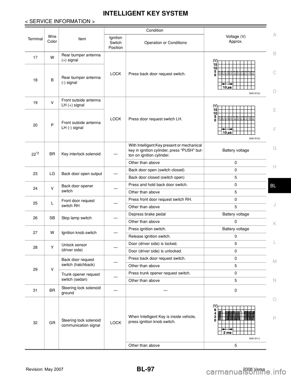
17 WRear bumper antenna
(+) signal
LOCK Press back door request switch.
18 BRear bumper antenna
(-) signal
19 VFront outside antenna
LH (+) signal
LOCK Press door request switch LH.
20 PFront outside antenna
LH (-) signal
22
*2BR Key interlock solenoid —With Intelligent Key present or mechanical
key in ignition cylinder, press "PUSH" but-
ton on ignition cylinder.Battery voltage
Other than above 0
23 LG Back door open output —Back door open (switch closed) 0
Back door closed (switch open) 5
24 VBack door opener
switch—Press and hold back door switch. 0
Other than above 5
25 LFront door request
switch RH—Press front door request switch RH. 0
Other than above 5
26 SB Stop lamp switch —Depress brake pedal Battery voltage
Other than above 0
27 W Ignition knob switch —Press ignition switch. Battery voltage
Release ignition switch. 0
28 YUnlock sensor
(driver side)—Door (driver side) is locked. 5
Door (driver side) is unlocked. 0
29 VBack door request
switch (hatchback)—Press back door request switch. 0
Other than above 5
Trunk opener request
switch (sedan)—Press trunk opener request switch. 0
Other than above 5
31 BRSteering lock solenoid
ground—— 0
32 GRSteering lock solenoid
communication signalLOCKWhen Intelligent Key is inside vehicle,
press ignition knob switch.
Other than above 5 TerminalWire
ColorItemCondition
Voltage (V)
Approx. Ignition
Switch
PositionOperation or Conditions
SIIA1910J
SIIA1910J
SIIA1911J
Page 738 of 2771

BRAKE PEDAL
BR-7
< SERVICE INFORMATION >
C
D
E
G
H
I
J
K
L
MA
B
BR
N
O
P
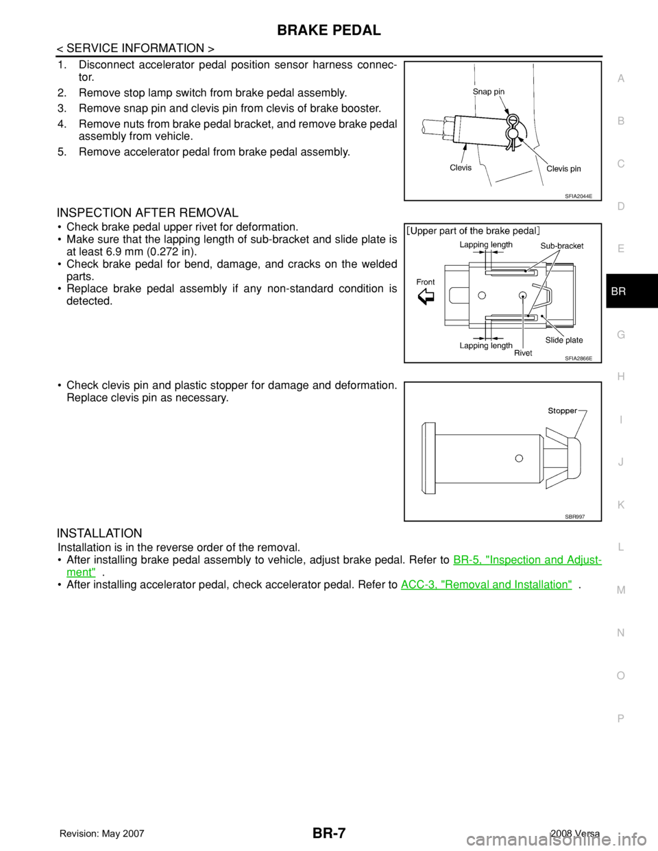
1. Disconnect accelerator pedal position sensor harness connec-
tor.
2. Remove stop lamp switch from brake pedal assembly.
3. Remove snap pin and clevis pin from clevis of brake booster.
4. Remove nuts from brake pedal bracket, and remove brake pedal
assembly from vehicle.
5. Remove accelerator pedal from brake pedal assembly.
INSPECTION AFTER REMOVAL
• Check brake pedal upper rivet for deformation.
• Make sure that the lapping length of sub-bracket and slide plate is
at least 6.9 mm (0.272 in).
• Check brake pedal for bend, damage, and cracks on the welded
parts.
• Replace brake pedal assembly if any non-standard condition is
detected.
• Check clevis pin and plastic stopper for damage and deformation.
Replace clevis pin as necessary.
INSTALLATION
Installation is in the reverse order of the removal.
• After installing brake pedal assembly to vehicle, adjust brake pedal. Refer to BR-5, "
Inspection and Adjust-
ment" .
• After installing accelerator pedal, check accelerator pedal. Refer to ACC-3, "
Removal and Installation" .
SFIA2044E
SFIA2866E
SBR997
Page 754 of 2771

FRONT DISC BRAKE
BR-23
< SERVICE INFORMATION >
C
D
E
G
H
I
J
K
L
MA
B
BR
N
O
P
FRONT DISC BRAKE
On Board InspectionINFOID:0000000001703796
PAD WEAR INSPECTION
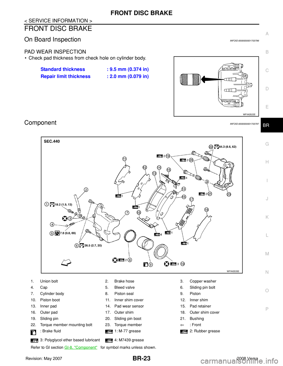
• Check pad thickness from check hole on cylinder body.
ComponentINFOID:0000000001703797
Standard thickness : 9.5 mm (0.374 in)
Repair limit thickness : 2.0 mm (0.079 in)
WFIA0522E
1. Union bolt 2. Brake hose 3. Copper washer
4. Cap 5. Bleed valve 6. Sliding pin bolt
7. Cylinder body 8. Piston seal 9. Piston
10. Piston boot 11. Inner shim cover 12. Inner shim
13. Inner pad 14. Pad wear sensor 15. Pad retainer
16. Outer pad 17. Outer shim 18. Outer shim cover
19. Sliding pin 20. Sliding pin boot 21. Bushing
22. Torque member mounting bolt 23. Torque member⇐: Front
: Brake fluid 1: M-77 grease 2: Rubber grease
3: Polyglycol ether based lubricant 4: M7439 grease
Refer to GI section GI-8, "
Component" for symbol marks unless shown.
WFIA0535E
Page 766 of 2771

BRC-1
BRAKES
C
D
E
G
H
I
J
K
L
M
SECTION BRC
A
B
BRC
N
O
P
CONTENTS
BRAKE CONTROL SYSTEM
ABS
SERVICE INFORMATION ............................
2
PRECAUTIONS ...................................................2
Precaution for Supplemental Restraint System
(SRS) "AIR BAG" and "SEAT BELT PRE-TEN-
SIONER" ...................................................................
2
Precaution for Brake System ....................................2
Precaution for Brake Control .....................................2
Precaution for CAN System ......................................3
PREPARATION ...................................................4
Special Service Tool .................................................4
Commercial Service Tool ..........................................4
SYSTEM DESCRIPTION .....................................5
System Component ...................................................5
ABS Function ............................................................5
EBD Function ............................................................5
Fail-Safe Function .....................................................5
Hydraulic Circuit Diagram .........................................6
CAN COMMUNICATION .....................................7
System Description ...................................................7
TROUBLE DIAGNOSIS ......................................8
How to Perform Trouble Diagnosis for Quick and
Accurate Repair ........................................................
8
Component Parts and Harness Connector Loca-
tion ..........................................................................
11
Schematic ...............................................................12
Wiring Diagram - ABS - ...........................................13
Basic Inspection ......................................................16
Warning Lamp and Indicator Timing ........................17
Control Unit Input/Output Signal Standard ..............17
CONSULT-III Function (ABS) ..................................18
TROUBLE DIAGNOSIS FOR SELF-DIAG-
NOSTIC ITEMS .................................................
24
Wheel Sensor System .............................................24
ABS Control Unit Inspection ....................................25
Solenoid Valve System Inspection ..........................25
Actuator Motor, Motor Relay, and Circuit Inspec-
tion ...........................................................................
26
ABS Control Unit Power and Ground Systems In-
spection ...................................................................
27
CAN Communication System Inspection .................28
TROUBLE DIAGNOSES FOR SYMPTOMS .....29
ABS Works Frequently ............................................29
Unexpected Pedal Action ........................................29
Long Stopping Distance ..........................................30
ABS Does Not Work ................................................30
Pedal Vibration or ABS Operation Noise .................30
WHEEL SENSORS ...........................................32
Removal and Installation .........................................32
SENSOR ROTOR ..............................................34
Removal and Installation .........................................34
ACTUATOR AND ELECTRIC UNIT (ASSEM-
BLY) ..................................................................
35
Removal and Installation .........................................35
Page 769 of 2771
![NISSAN LATIO 2008 Service Repair Manual BRC-4
< SERVICE INFORMATION >[ABS]
PREPARATION
PREPARATION
Special Service ToolINFOID:0000000001703823
The actual shapes of Kent-Moore tools may differ from those of special service tools illustrated NISSAN LATIO 2008 Service Repair Manual BRC-4
< SERVICE INFORMATION >[ABS]
PREPARATION
PREPARATION
Special Service ToolINFOID:0000000001703823
The actual shapes of Kent-Moore tools may differ from those of special service tools illustrated](/manual-img/5/57360/w960_57360-768.png)
BRC-4
< SERVICE INFORMATION >[ABS]
PREPARATION
PREPARATION
Special Service ToolINFOID:0000000001703823
The actual shapes of Kent-Moore tools may differ from those of special service tools illustrated here.
Commercial Service ToolINFOID:0000000001703824
Tool number
(Kent-Moore No.)
Tool nameDescription
KV991J0080
(J-45741)
ABS active wheel sensor testerChecking operation of ABS active wheel sen-
sors
WFIA0101E
Tool nameDescription
1. Flare nut crowfoot
2. Torque wrenchRemoving and installing brake piping
a: 10 mm (0.39 in)/12 mm (0.47 in)
S-NT360
Page 773 of 2771
![NISSAN LATIO 2008 Service Repair Manual BRC-8
< SERVICE INFORMATION >[ABS]
TROUBLE DIAGNOSIS
TROUBLE DIAGNOSIS
How to Perform Trouble Diagnosis for Quick and Accurate RepairINFOID:0000000001703831
INTRODUCTION
The ABS system has an electron NISSAN LATIO 2008 Service Repair Manual BRC-8
< SERVICE INFORMATION >[ABS]
TROUBLE DIAGNOSIS
TROUBLE DIAGNOSIS
How to Perform Trouble Diagnosis for Quick and Accurate RepairINFOID:0000000001703831
INTRODUCTION
The ABS system has an electron](/manual-img/5/57360/w960_57360-772.png)
BRC-8
< SERVICE INFORMATION >[ABS]
TROUBLE DIAGNOSIS
TROUBLE DIAGNOSIS
How to Perform Trouble Diagnosis for Quick and Accurate RepairINFOID:0000000001703831
INTRODUCTION
The ABS system has an electronic control unit to control major func-
tions. The control unit accepts input signals from sensors and con-
trols actuator operation. It is also important to check for air leaks in
the booster or brake and vacuum lines, lack of brake fluid, or other
malfunctions in the brake system.
It is much more difficult to diagnose a malfunction that occurs inter-
mittently rather than continuously. Most intermittent conditions are
caused by poor electrical connections or damaged wiring. In this
case, careful checking of suspicious circuits may help prevent the
replacement of good parts.
A visual check only may not find the cause of the malfunction, so a
road test should be performed.
Before undertaking actual checks, take just a few minutes to talk with
a customer who approaches with an ABS complaint. The customer
is a very good source of information, especially for intermittent condi-
tions. Through the talks with the customer, find out what symptoms
are present and under what conditions they occur.
Start your diagnosis by looking for “conventional” malfunctions first.
This is one of the best ways to troubleshoot brake malfunctions on
an ABS equipped vehicle. Also check related Service Bulletins for
information.
SEF233G
SEF234G