2008 NISSAN LATIO brake sensor
[x] Cancel search: brake sensorPage 1022 of 2771

DI-1
ELECTRICAL
C
D
E
F
G
H
I
J
L
M
SECTION DI
A
B
DI
N
O
P
CONTENTS
DRIVER INFORMATION SYSTEM
SERVICE INFORMATION ............................2
PRECAUTION .....................................................2
Precaution for Supplemental Restraint System
(SRS) "AIR BAG" and "SEAT BELT PRE-TEN-
SIONER" ...................................................................
2
PREPARATION ...................................................3
Commercial Service Tool ..........................................3
COMBINATION METERS ...................................4
Component Parts and Harness Connector Loca-
tion ............................................................................
4
System Description ...................................................4
Arrangement of Combination Meter ..........................6
Internal Circuit ...........................................................7
Wiring Diagram - METER - .......................................8
Combination Meter Harness Connector Terminal
Layout .....................................................................
10
Terminal and Reference Value for Combination
Meter .......................................................................
10
Self-Diagnosis Mode of Combination Meter ............11
CONSULT-III Function (METER/M&A) ...................13
Trouble Diagnosis ...................................................14
Symptom Chart .......................................................15
Power Supply and Ground Circuit Inspection .........15
Vehicle Speed Signal Inspection .............................16
Engine Speed Signal Inspection .............................17
Fuel Level Sensor Signal Inspection .......................17
Fuel Gauge Fluctuates, Indicates Wrong Value, or
Varies ......................................................................
19
Fuel Gauge Does Not Move to Full-position ...........19
DTC [U1000] CAN Communication Circuit .............19
Electrical Component Inspection .............................19
Removal and Installation .........................................20
WARNING LAMPS .............................................21
Schematic ................................................................21
Wiring Diagram - WARN - .......................................22
Oil Pressure Warning Lamp Stays Off (Ignition
Switch ON) ..............................................................
30
Oil Pressure Warning Lamp Does Not Turn Off
(Oil Pressure Is Normal) ..........................................
32
Component Inspection .............................................32
A/T INDICATOR ................................................34
System Description ..................................................34
Wiring Diagram - AT/IND - .......................................35
A/T Indicator Does Not Illuminate ............................36
CVT INDICATOR ...............................................38
System Description ..................................................38
Wiring Diagram - CVTIND - .....................................38
CVT Indicator Does Not Illuminate ..........................39
WARNING CHIME .............................................41
Component Parts and Harness Connector Loca-
tion ...........................................................................
41
System Description ..................................................41
Wiring Diagram - CHIME - .......................................44
Terminal and Reference Value for BCM ..................45
CONSULT-III Function (BCM) .................................45
Trouble Diagnosis ....................................................46
Combination Meter Buzzer Circuit Inspection .........47
Front Door Switch LH Signal Inspection ..................48
Key Switch Signal Inspection (Without Intelligent
Key) .........................................................................
49
Key Switch and Ignition Knob Switch Signal In-
spection (With Intelligent Key, When Mechanical
Key Is Used) ............................................................
50
Lighting Switch Signal Inspection ............................52
Parking Brake Switch Signal Inspection ..................52
Electrical Component Inspection .............................53
Page 1031 of 2771
DI-10
< SERVICE INFORMATION >
COMBINATION METERS
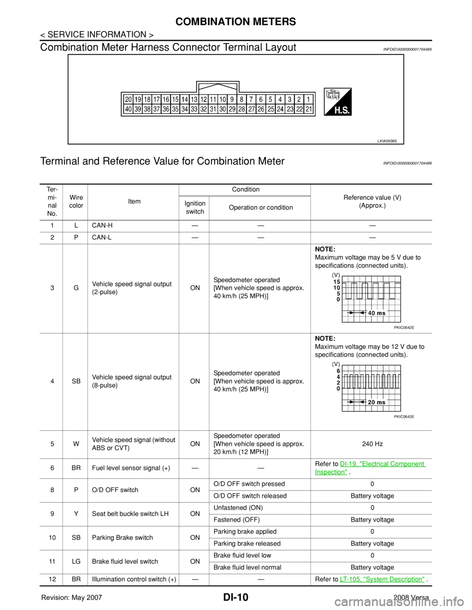
Combination Meter Harness Connector Terminal Layout
INFOID:0000000001704495
Terminal and Reference Value for Combination MeterINFOID:0000000001704496
LKIA0698E
Te r -
mi-
nal
No.Wire
colorItemCondition
Reference value (V)
(Approx.) Ignition
switchOperation or condition
1LCAN-H — — —
2PCAN-L — — —
3GVehicle speed signal output
(2-pulse)ONSpeedometer operated
[When vehicle speed is approx.
40 km/h (25 MPH)] NOTE:
Maximum voltage may be 5 V due to
specifications (connected units).
4SBVehicle speed signal output
(8-pulse)ONSpeedometer operated
[When vehicle speed is approx.
40 km/h (25 MPH)]NOTE:
Maximum voltage may be 12 V due to
specifications (connected units).
5WVehicle speed signal (without
ABS or CVT)ONSpeedometer operated
[When vehicle speed is approx.
20 km/h (12 MPH)]240 Hz
6 BR Fuel level sensor signal (+) — —Refer to DI-19, "
Electrical Component
Inspection" .
8 P O/D OFF switch ONO/D OFF switch pressed 0
O/D OFF switch released Battery voltage
9 Y Seat belt buckle switch LH ONUnfastened (ON) 0
Fastened (OFF) Battery voltage
10 SB Parking Brake switch ONParking brake applied 0
Parking brake released Battery voltage
11 LG Brake fluid level switch ONBrake fluid level low 0
Brake fluid level normal Battery voltage
12 BR Illumination control switch (+) — — Refer to LT- 1 0 5 , "
System Description" .
PKIC0642E
PKIC0643E
Page 1032 of 2771
COMBINATION METERS
DI-11
< SERVICE INFORMATION >
C
D
E
F
G
H
I
J
L
MA
B
DI
N
O
P
Self-Diagnosis Mode of Combination MeterINFOID:0000000001704497
SELF-DIAGNOSIS MODE FUNCTION
• Self-diagnosis can check for continuity between meter control circuit and each meter (speedometer, tachom-
eter and fuel gauge).
• Self-diagnosis can check for odo/trip meter and A/T indicator (with A/T) or CVT indicator (with CVT) seg-
ment, low-fuel level warning lamp, low water temperature indicator lamp, and high water temperature warn-
ing lamp.
OPERATION PROCEDURE
1. Turn the ignition switch ON, and switch the odo/trip meter to “trip A” or “trip B”.
NOTE:
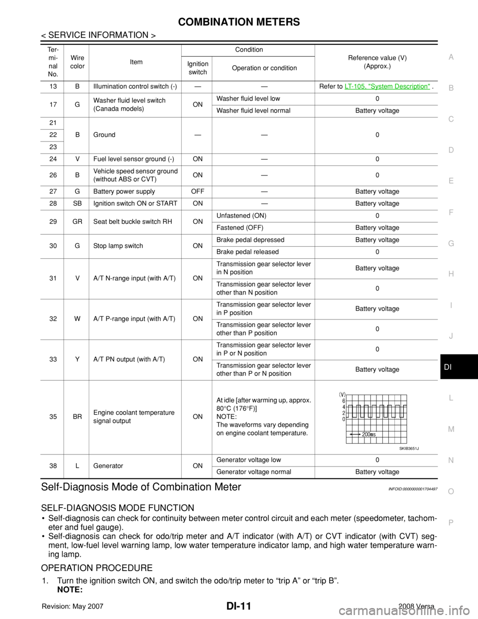
13 B Illumination control switch (-) — — Refer to LT- 1 0 5 , "System Description" .
17 GWasher fluid level switch
(Canada models)ONWasher fluid level low 0
Washer fluid level normal Battery voltage
21
BGround — — 0 22
23
24 V Fuel level sensor ground (-) ON — 0
26 BVehicle speed sensor ground
(without ABS or CVT)ON — 0
27 G Battery power supply OFF — Battery voltage
28 SB Ignition switch ON or START ON — Battery voltage
29 GR Seat belt buckle switch RH ONUnfastened (ON) 0
Fastened (OFF) Battery voltage
30 G Stop lamp switch ONBrake pedal depressed Battery voltage
Brake pedal released 0
31 V A/T N-range input (with A/T) ONTransmission gear selector lever
in N positionBattery voltage
Transmission gear selector lever
other than N position0
32 W A/T P-range input (with A/T) ONTransmission gear selector lever
in P positionBattery voltage
Transmission gear selector lever
other than P position0
33 Y A/T PN output (with A/T) ONTransmission gear selector lever
in P or N position0
Transmission gear selector lever
other than P or N positionBattery voltage
35 BREngine coolant temperature
signal outputONAt idle [after warming up, approx.
80°C (176°F)]
NOTE:
The waveforms vary depending
on engine coolant temperature.
38 L Generator ONGenerator voltage low 0
Generator voltage normal Battery voltage Te r -
mi-
nal
No.Wire
colorItemCondition
Reference value (V)
(Approx.) Ignition
switchOperation or condition
SKIB3651J
Page 1064 of 2771
WARNING CHIME
DI-43
< SERVICE INFORMATION >
C
D
E
F
G
H
I
J
L
MA
B
DI
N
O
P
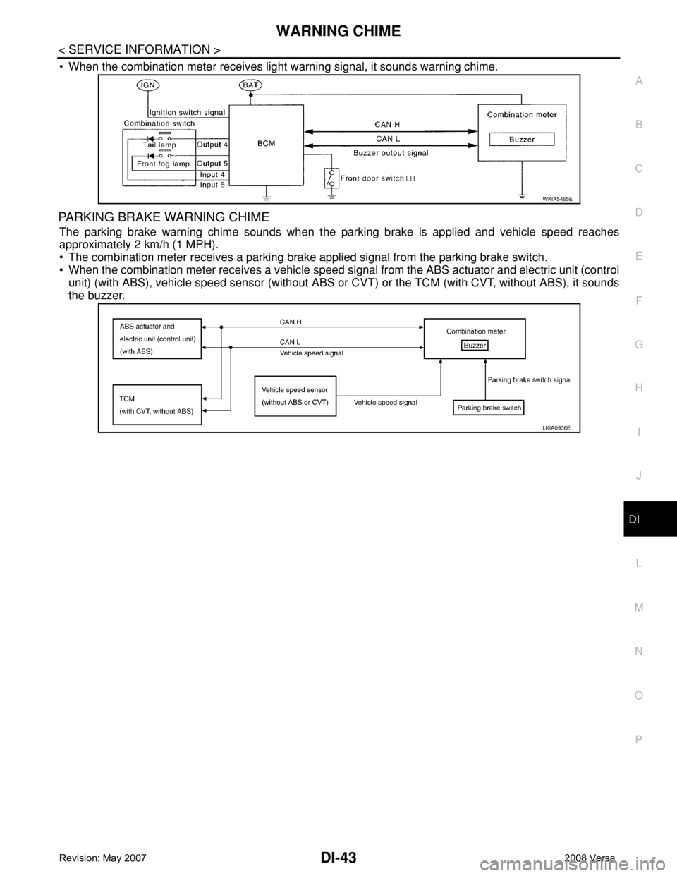
• When the combination meter receives light warning signal, it sounds warning chime.
PARKING BRAKE WARNING CHIME
The parking brake warning chime sounds when the parking brake is applied and vehicle speed reaches
approximately 2 km/h (1 MPH).
• The combination meter receives a parking brake applied signal from the parking brake switch.
• When the combination meter receives a vehicle speed signal from the ABS actuator and electric unit (control
unit) (with ABS), vehicle speed sensor (without ABS or CVT) or the TCM (with CVT, without ABS), it sounds
the buzzer.
WKIA5465E
LKIA0906E
Page 1080 of 2771

EC-6
Overall Function Check .........................................406
Wiring Diagram ......................................................407
Diagnosis Procedure .............................................408
DTC P1148 CLOSED LOOP CONTROL .........411
On Board Diagnosis Logic .....................................411
DTC P1217 ENGINE OVER TEMPERATURE .412
System Description ................................................412
CONSULT-II Reference Value in Data Monitor
Mode ......................................................................
413
On Board Diagnosis Logic .....................................413
Overall Function Check .........................................413
Wiring Diagram ......................................................416
Diagnosis Procedure .............................................417
Main 13 Causes of Overheating ............................424
Component Inspection ...........................................424
DTC P1225 TP SENSOR .................................426
Component Description .........................................426
On Board Diagnosis Logic .....................................426
DTC Confirmation Procedure ................................426
Diagnosis Procedure .............................................426
Removal and Installation .......................................427
DTC P1226 TP SENSOR .................................428
Component Description .........................................428
On Board Diagnosis Logic .....................................428
DTC Confirmation Procedure ................................428
Diagnosis Procedure .............................................428
Removal and Installation .......................................429
DTC P1421 COLD START CONTROL ............430
Description .............................................................430
On Board Diagnosis Logic .....................................430
DTC Confirmation Procedure ................................430
Diagnosis Procedure .............................................430
DTC P1564 ASCD STEERING SWITCH .........432
Component Description .........................................432
CONSULT-II Reference Value in Data Monitor
Mode ......................................................................
432
On Board Diagnosis Logic .....................................432
DTC Confirmation Procedure ................................433
Wiring Diagram ......................................................434
Diagnosis Procedure .............................................435
Component Inspection ...........................................437
DTC P1572 ASCD BRAKE SWITCH ..............438
Component Description .........................................438
CONSULT-II Reference Value in Data Monitor
Mode ......................................................................
438
On Board Diagnosis Logic .....................................438
DTC Confirmation Procedure ................................439
Wiring Diagram ......................................................440
Diagnosis Procedure .............................................441
Component Inspection ...........................................445
DTC P1574 ASCD VEHICLE SPEED SEN-
SOR ..................................................................
447
Component Description .........................................447
On Board Diagnosis Logic ....................................447
DTC Confirmation Procedure ................................447
Diagnosis Procedure .............................................448
DTC P1715 INPUT SPEED SENSOR (TUR-
BINE REVOLUTION SENSOR) ........................
449
Description ............................................................449
CONSULT-II Reference Value in Data Monitor
Mode .....................................................................
449
On Board Diagnosis Logic ....................................449
Diagnosis Procedure .............................................449
DTC P1715 INPUT SPEED SENSOR (PRIMA-
RY SPEED SENSOR) .......................................
450
Description ............................................................450
CONSULT-II Reference Value in Data Monitor
Mode .....................................................................
450
On Board Diagnosis Logic ....................................450
DTC Confirmation Procedure ................................450
Diagnosis Procedure .............................................451
DTC P1805 BRAKE SWITCH ..........................452
Description ............................................................452
CONSULT-II Reference Value in Data Monitor
Mode .....................................................................
452
On Board Diagnosis Logic ....................................452
DTC Confirmation Procedure ................................452
Wiring Diagram .....................................................453
Diagnosis Procedure .............................................454
Component Inspection ..........................................455
DTC P2100, P2103 THROTTLE CONTROL
MOTOR RELAY ................................................
456
Component Description ........................................456
CONSULT-II Reference Value in Data Monitor
Mode .....................................................................
456
On Board Diagnosis Logic ....................................456
DTC Confirmation Procedure ................................456
Wiring Diagram .....................................................458
Diagnosis Procedure .............................................459
DTC P2101 ELECTRIC THROTTLE CON-
TROL FUNCTION .............................................
461
Description ............................................................461
On Board Diagnosis Logic ....................................461
DTC Confirmation Procedure ................................461
Wiring Diagram .....................................................462
Diagnosis Procedure .............................................463
Component Inspection ..........................................466
Removal and Installation .......................................466
DTC P2118 THROTTLE CONTROL MOTOR ..467
Component Description ........................................467
On Board Diagnosis Logic ....................................467
DTC Confirmation Procedure ................................467
Wiring Diagram .....................................................468
Diagnosis Procedure .............................................469
Component Inspection ..........................................470
Removal and Installation .......................................470
Page 1081 of 2771

EC-7
C
D
E
F
G
H
I
J
K
L
M
ECA
N
O
P
DTC P2119 ELECTRIC THROTTLE CON-
TROL ACTUATOR ...........................................
472
Component Description .........................................472
On Board Diagnosis Logic ....................................472
DTC Confirmation Procedure ................................472
Diagnosis Procedure .............................................473
DTC P2122, P2123 APP SENSOR ..................474
Component Description .........................................474
CONSULT-II Reference Value in Data Monitor
Mode .....................................................................
474
On Board Diagnosis Logic ....................................474
DTC Confirmation Procedure ................................474
Wiring Diagram .....................................................476
Diagnosis Procedure .............................................477
Component Inspection ..........................................479
Removal and Installation .......................................479
DTC P2127, P2128 APP SENSOR ..................480
Component Description .........................................480
CONSULT-II Reference Value in Data Monitor
Mode .....................................................................
480
On Board Diagnosis Logic ....................................480
DTC Confirmation Procedure ................................481
Wiring Diagram .....................................................482
Diagnosis Procedure .............................................483
Component Inspection ..........................................485
Removal and Installation .......................................486
DTC P2135 TP SENSOR .................................487
Component Description .........................................487
CONSULT-II Reference Value in Data Monitor
Mode .....................................................................
487
On Board Diagnosis Logic ....................................487
DTC Confirmation Procedure ................................487
Wiring Diagram .....................................................489
Diagnosis Procedure .............................................490
Component Inspection ..........................................492
Removal and Installation .......................................492
DTC P2138 APP SENSOR ...............................493
Component Description .........................................493
CONSULT-II Reference Value in Data Monitor
Mode .....................................................................
493
On Board Diagnosis Logic ....................................493
DTC Confirmation Procedure ................................494
Wiring Diagram .....................................................495
Diagnosis Procedure .............................................496
Component Inspection ..........................................499
Removal and Installation .......................................499
DTC P2A00 A/F SENSOR 1 .............................500
Component Description .........................................500
CONSULT-II Reference Value in Data Monitor
Mode .....................................................................
500
On Board Diagnosis Logic ....................................500
DTC Confirmation Procedure ................................500
Wiring Diagram .....................................................502
Diagnosis Procedure .............................................503
Removal and Installation .......................................507
ASCD BRAKE SWITCH ..................................508
Component Description .........................................508
CONSULT-II Reference Value in Data Monitor
Mode ......................................................................
508
Wiring Diagram ......................................................509
Diagnosis Procedure .............................................510
Component Inspection ...........................................514
ASCD INDICATOR ..........................................516
Component Description .........................................516
CONSULT-II Reference Value in Data Monitor
Mode ......................................................................
516
Wiring Diagram ......................................................517
Diagnosis Procedure .............................................517
ELECTRICAL LOAD SIGNAL ........................519
CONSULT-II Reference Value in Data Monitor
Mode ......................................................................
519
Diagnosis Procedure .............................................519
FUEL INJECTOR ............................................521
Component Description .........................................521
CONSULT-II Reference Value in Data Monitor
Mode ......................................................................
521
Wiring Diagram ......................................................522
Diagnosis Procedure .............................................523
Component Inspection ...........................................525
Removal and Installation .......................................525
FUEL PUMP ....................................................526
Description .............................................................526
CONSULT-II Reference Value in Data Monitor
Mode ......................................................................
526
Wiring Diagram ......................................................527
Diagnosis Procedure .............................................528
Component Inspection ...........................................530
Removal and Installation .......................................530
IGNITION SIGNAL ..........................................531
Component Description .........................................531
Wiring Diagram ......................................................532
Diagnosis Procedure .............................................535
Component Inspection ...........................................538
Removal and Installation .......................................540
REFRIGERANT PRESSURE SENSOR ..........541
Component Description .........................................541
Wiring Diagram ......................................................542
Diagnosis Procedure .............................................543
Removal and Installation .......................................545
MIL AND DATA LINK CONNECTOR .............546
Wiring Diagram ......................................................546
SERVICE DATA AND SPECIFICATIONS
(SDS) ...............................................................
548
Fuel Pressure ........................................................548
Idle Speed and Ignition Timing ..............................548
Calculated Load Value ..........................................548
Mass Air Flow Sensor ............................................548
Intake Air Temperature Sensor .............................548
Page 1085 of 2771
INDEX FOR DTC
EC-11
< SERVICE INFORMATION >
C
D
E
F
G
H
I
J
K
L
MA
EC
N
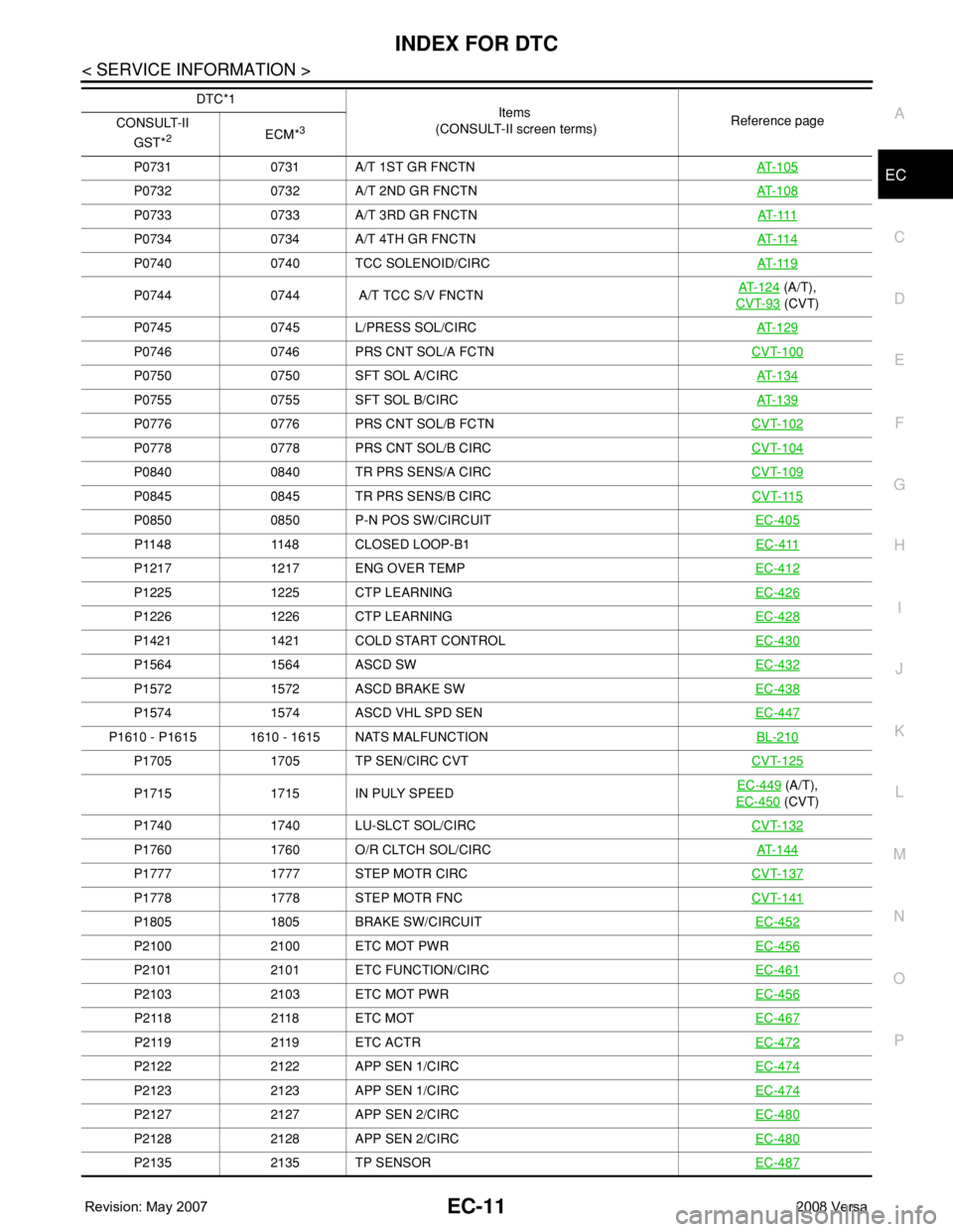
P OP0731 0731 A/T 1ST GR FNCTNAT- 1 0 5
P0732 0732 A/T 2ND GR FNCTNAT- 1 0 8
P0733 0733 A/T 3RD GR FNCTNAT- 111
P0734 0734 A/T 4TH GR FNCTNAT- 11 4
P0740 0740 TCC SOLENOID/CIRCAT- 11 9
P0744 0744 A/T TCC S/V FNCTNAT- 1 2 4 (A/T),
CVT-93
(CVT)
P0745 0745 L/PRESS SOL/CIRCAT- 1 2 9
P0746 0746 PRS CNT SOL/A FCTNCVT-100
P0750 0750 SFT SOL A/CIRCAT- 1 3 4
P0755 0755 SFT SOL B/CIRCAT- 1 3 9
P0776 0776 PRS CNT SOL/B FCTNCVT-102
P0778 0778 PRS CNT SOL/B CIRCCVT-104
P0840 0840 TR PRS SENS/A CIRCCVT-109
P0845 0845 TR PRS SENS/B CIRCCVT-115
P0850 0850 P-N POS SW/CIRCUITEC-405
P1148 1148 CLOSED LOOP-B1EC-411
P1217 1217 ENG OVER TEMPEC-412
P1225 1225 CTP LEARNINGEC-426
P1226 1226 CTP LEARNINGEC-428
P1421 1421 COLD START CONTROLEC-430
P1564 1564 ASCD SWEC-432
P1572 1572 ASCD BRAKE SWEC-438
P1574 1574 ASCD VHL SPD SENEC-447
P1610 - P1615 1610 - 1615 NATS MALFUNCTIONBL-210
P1705 1705 TP SEN/CIRC CVTCVT-125
P1715 1715 IN PULY SPEEDEC-449 (A/T),
EC-450
(CVT)
P1740 1740 LU-SLCT SOL/CIRCCVT-132
P1760 1760 O/R CLTCH SOL/CIRCAT- 1 4 4
P1777 1777 STEP MOTR CIRCCVT-137
P1778 1778 STEP MOTR FNCCVT-141
P1805 1805 BRAKE SW/CIRCUITEC-452
P2100 2100 ETC MOT PWREC-456
P2101 2101 ETC FUNCTION/CIRCEC-461
P2103 2103 ETC MOT PWREC-456
P 2 11 8 2 11 8 E T C M O TEC-467
P 2 11 9 2 11 9 E T C A C T REC-472
P2122 2122 APP SEN 1/CIRCEC-474
P2123 2123 APP SEN 1/CIRCEC-474
P2127 2127 APP SEN 2/CIRCEC-480
P2128 2128 APP SEN 2/CIRCEC-480
P2135 2135 TP SENSOREC-487
DTC*1
Items
(CONSULT-II screen terms)Reference page
CONSULT-II
GST*
2ECM*3
Page 1086 of 2771
EC-12
< SERVICE INFORMATION >
INDEX FOR DTC
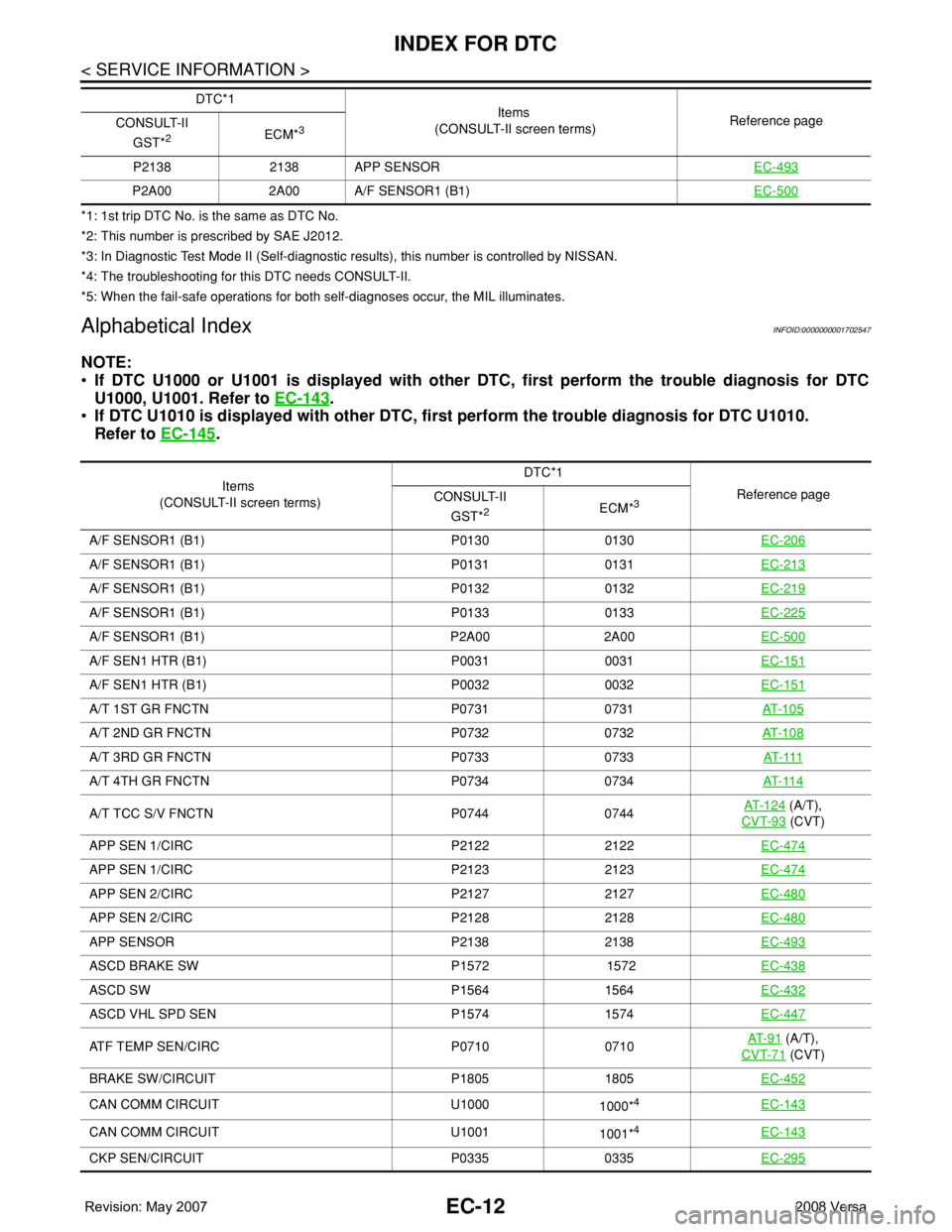
*1: 1st trip DTC No. is the same as DTC No.
*2: This number is prescribed by SAE J2012.
*3: In Diagnostic Test Mode II (Self-diagnostic results), this number is controlled by NISSAN.
*4: The troubleshooting for this DTC needs CONSULT-II.
*5: When the fail-safe operations for both self-diagnoses occur, the MIL illuminates.
Alphabetical IndexINFOID:0000000001702547
NOTE:
•If DTC U1000 or U1001 is displayed with other DTC, first perform the trouble diagnosis for DTC
U1000, U1001. Refer to EC-143
.
•If DTC U1010 is displayed with other DTC, first perform the trouble diagnosis for DTC U1010.
Refer to EC-145
.
P2138 2138 APP SENSOREC-493
P2A00 2A00 A/F SENSOR1 (B1)EC-500
DTC*1
Items
(CONSULT-II screen terms)Reference page
CONSULT-II
GST*
2ECM*3
Items
(CONSULT-II screen terms)DTC*1
Reference page
CONSULT-II
GST*
2ECM*3
A/F SENSOR1 (B1) P0130 0130EC-206
A/F SENSOR1 (B1) P0131 0131EC-213
A/F SENSOR1 (B1) P0132 0132EC-219
A/F SENSOR1 (B1) P0133 0133EC-225
A/F SENSOR1 (B1) P2A00 2A00EC-500
A/F SEN1 HTR (B1) P0031 0031EC-151
A/F SEN1 HTR (B1) P0032 0032EC-151
A/T 1ST GR FNCTN P0731 0731AT- 1 0 5
A/T 2ND GR FNCTN P0732 0732AT- 1 0 8
A/T 3RD GR FNCTN P0733 0733AT- 111
A/T 4TH GR FNCTN P0734 0734AT- 11 4
A/T TCC S/V FNCTN P0744 0744AT- 1 2 4 (A/T),
CVT-93
(CVT)
APP SEN 1/CIRC P2122 2122EC-474
APP SEN 1/CIRC P2123 2123EC-474
APP SEN 2/CIRC P2127 2127EC-480
APP SEN 2/CIRC P2128 2128EC-480
APP SENSOR P2138 2138EC-493
ASCD BRAKE SW P1572 1572EC-438
ASCD SW P1564 1564EC-432
ASCD VHL SPD SEN P1574 1574EC-447
ATF TEMP SEN/CIRC P0710 0710AT- 9 1 (A/T),
CVT-71
(CVT)
BRAKE SW/CIRCUIT P1805 1805EC-452
CAN COMM CIRCUIT U1000
1000*4EC-143
CAN COMM CIRCUIT U1001
1001*4EC-143
CKP SEN/CIRCUIT P0335 0335EC-295