2008 NISSAN LATIO brake sensor
[x] Cancel search: brake sensorPage 15 of 2771

AT-3
D
E
F
G
H
I
J
K
L
MA
B
AT
N
O
P N Wiring Diagram - AT - SSV/B ................................
140
Diagnosis Procedure .............................................141
Component Inspection ..........................................142
DTC P1760 OVERRUN CLUTCH SOLENOID
VALVE ..............................................................
144
Description ............................................................144
CONSULT-III Reference Value in Data Monitor
Mode .....................................................................
144
On Board Diagnosis Logic ....................................144
Possible Cause .....................................................144
DTC Confirmation Procedure ................................144
Wiring Diagram - AT - OVRCSV ...........................145
Diagnosis Procedure .............................................146
Component Inspection ..........................................147
DTC VEHICLE SPEED SENSOR MTR ............149
Description ............................................................149
CONSULT-III Reference Value in Data Monitor
Mode .....................................................................
149
On Board Diagnosis Logic ....................................149
Possible Cause .....................................................149
DTC Confirmation Procedure ................................149
Wiring Diagram - AT - VSSMTR ...........................150
Diagnosis Procedure .............................................151
DTC BATT/FLUID TEMP SEN (A/T FLUID
TEMP SENSOR CIRCUIT AND TCM POWER
SOURCE) .........................................................
152
Description ............................................................152
CONSULT-III Reference Value in Data Monitor
Mode .....................................................................
152
On Board Diagnosis Logic ....................................152
Possible Cause .....................................................152
DTC Confirmation Procedure ................................152
Wiring Diagram - AT - BA/FTS ..............................153
Diagnosis Procedure .............................................154
Component Inspection ..........................................156
DTC TURBINE REVOLUTION SENSOR .........158
Description ............................................................158
CONSULT-III Reference Value in Data Monitor
Mode .....................................................................
158
On Board Diagnosis Logic ....................................158
Possible Cause .....................................................158
DTC Confirmation Procedure ................................158
Wiring Diagram - AT - PT/SEN .............................159
Diagnosis Procedure .............................................160
CONTROL UNIT (RAM), CONTROL UNIT
(ROM) ...............................................................
163
Description ............................................................163
On Board Diagnosis Logic ....................................163
Possible Cause .....................................................163
DTC Confirmation Procedure ................................163
Diagnosis Procedure .............................................163
MAIN POWER SUPPLY AND GROUND CIR-
CUIT ..................................................................
164
Wiring Diagram - AT - MAIN .................................164
Diagnosis Procedure .............................................165
PNP, OD SWITCH AND CLOSED THROT-
TLE, WIDE OPEN THROTTLE POSITION
SIGNAL CIRCUIT ............................................
167
CONSULT-III Reference Value in Data Monitor
Mode ......................................................................
167
TCM Terminal and Reference Value .....................167
Diagnosis Procedure .............................................167
Component Inspection ...........................................171
SHIFT POSITION INDICATOR CIRCUIT ........172
Description .............................................................172
CONSULT-III Reference Value in Data Monitor
Mode ......................................................................
172
Diagnosis Procedure .............................................172
TROUBLE DIAGNOSIS FOR SYMPTOMS ....173
Wiring Diagram - AT - NONDTC ...........................173
OD OFF Indicator Lamp Does Not Come On ........176
Engine Cannot Be Started in "P" and "N" Position ..178
In "P" Position, Vehicle Moves Forward or Back-
ward When Pushed ...............................................
179
In "N" Position, Vehicle Moves ..............................179
Large Shock "N" → "R" Position ............................180
Vehicle Does Not Creep Backward in "R" Position ..181
Vehicle Does Not Creep Forward in "D", "2" or "1"
Position ..................................................................
182
Vehicle Cannot Be Started from D1 .......................183
A/T Does Not Shift: D1→ D2or Does Not Kick-
down: D
4→ D2 .......................................................185
A/T Does Not Shift: D2→ D3 ..................................186
A/T Does Not Shift: D3→ D4 ..................................188
A/T Does Not Perform Lock-up .............................189
A/T Does Not Hold Lock-up Condition ...................190
Lock-up Is Not Released .......................................191
Engine Speed Does Not Return to Idle (Light
Braking D
4→ D3) ...................................................192
A/T Does Not Shift: D4→ D3, When OD OFF ........193
A/T Does Not Shift: D3→ 22, When Selector Lever
"D" → "2" Position .................................................
194
A/T Does Not Shift: 22→ 11, When Selector Lever
"2" → "1" Position ..................................................
195
Vehicle Does Not Decelerate by Engine Brake .....197
TCM Self-Diagnosis Does Not Activate .................200
TRANSMISSION CONTROL MODULE ..........202
Removal and Installation .......................................202
SHIFT CONTROL SYSTEM ............................203
Control Device Removal and Installation ...............203
Control Device Disassembly and Assembly ..........206
Selector Lever Knob Removal and Installation ......206
Adjustment of A/T Position ....................................207
Checking of A/T Position .......................................207
A/T SHIFT LOCK SYSTEM .............................209
Description .............................................................209
Shift Lock System Parts Location ..........................209
Wiring Diagram - AT - SHIFT ................................210
Page 16 of 2771

AT-4
Diagnosis Procedure .............................................210
KEY INTERLOCK CABLE ...............................213
Removal and Installation .......................................213
ON-VEHICLE SERVICE ..................................216
Control Valve Assembly and Accumulators ...........216
Park/Neutral Position (PNP) Switch ......................219
Revolution Sensor .................................................221
Turbine Revolution Sensor (Power Train Revolu-
tion Sensor) ...........................................................
222
Differential Side Oil Seal ........................................223
AIR BREATHER HOSE ...................................225
Removal and Installation .......................................225
TRANSAXLE ASSEMBLY ..............................226
Removal and Installation .......................................226
OVERHAUL .....................................................230
Component ............................................................230
Oil Channel ............................................................237
Location of Adjusting Shims, Needle Bearings and
Thrust Washers .....................................................
238
Location of Snap Rings .........................................239
DISASSEMBLY ...............................................240
Disassembly ..........................................................240
REPAIR FOR COMPONENT PARTS ..............257
Manual Shaft .........................................................257
Oil Pump ................................................................260
Control Valve Assembly ........................................263
Control Valve Upper Body .....................................272
Control Valve Lower Body .....................................276
Reverse Clutch ......................................................279
High Clutch ............................................................284
Forward and Overrun Clutches .............................288
Low & Reverse Brake ............................................295
Rear Internal Gear and Forward Clutch Hub .........299
Output Shaft, Output Gear, Idler Gear, Reduction
Pinion Gear and Bearing Retainer .........................
302
Band Servo Piston Assembly ................................307
Final Drive .............................................................313
ASSEMBLY ......................................................318
Assembly (1) .........................................................318
Adjustment (1) .......................................................319
Assembly (2) .........................................................325
Adjustment (2) .......................................................330
Assembly (3) .........................................................333
SERVICE DATA AND SPECIFICATIONS
(SDS) ................................................................
341
General Specification ............................................341
Vehicle Speed at Which Gear Shifting Occurs .....341
Vehicle Speed at When Lock-up Occurs/Releases
.
341
Stall Speed ............................................................341
Line Pressure ........................................................341
Adjusting shims, Needle Bearings, Thrust Wash-
ers and Snap Rings ..............................................
341
Control Valves .......................................................343
Accumulator ..........................................................343
Clutches and Brakes .............................................343
Final Drive .............................................................345
Planetary Carrier ...................................................345
Oil Pump ...............................................................345
Input Shaft .............................................................345
Reduction Pinion Gear ..........................................345
Band Servo ...........................................................345
Output Shaft ..........................................................346
Bearing Retainer ...................................................346
Total End Play .......................................................346
Reverse Clutch End Play ......................................346
Removal and Installation .......................................346
Shift Solenoid Valves ............................................346
Solenoid Valves ....................................................346
A/T Fluid Temperature Sensor ..............................347
Revolution Sensor .................................................347
Dropping Resistor .................................................347
Turbine Revolution Sensor (Power Train Revolu-
tion Sensor) ...........................................................
347
Page 39 of 2771
A/T CONTROL SYSTEM
AT-27
< SERVICE INFORMATION >
D
E
F
G
H
I
J
K
L
MA
B
AT
N
O
P
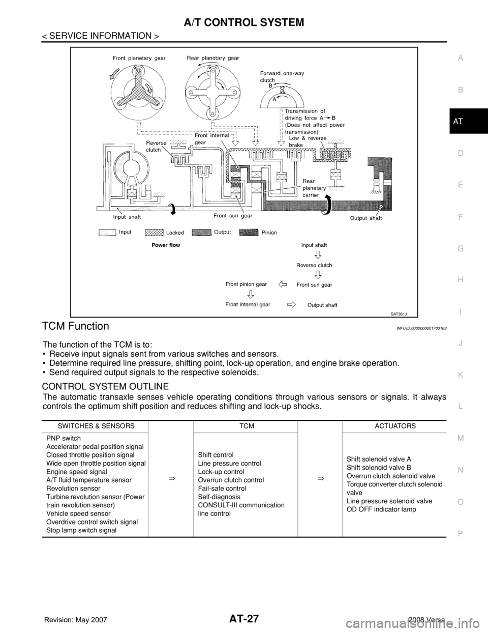
TCM FunctionINFOID:0000000001703163
The function of the TCM is to:
• Receive input signals sent from various switches and sensors.
• Determine required line pressure, shifting point, lock-up operation, and engine brake operation.
• Send required output signals to the respective solenoids.
CONTROL SYSTEM OUTLINE
The automatic transaxle senses vehicle operating conditions through various sensors or signals. It always
controls the optimum shift position and reduces shifting and lock-up shocks.
SAT381J
SWITCHES & SENSORS
⇒TCM
⇒ACTUATORS
PNP switch
Accelerator pedal position signal
Closed throttle position signal
Wide open throttle position signal
Engine speed signal
A/T fluid temperature sensor
Revolution sensor
Turbine revolution sensor (Power
train revolution sensor)
Vehicle speed sensor
Overdrive control switch signal
Stop lamp switch signalShift control
Line pressure control
Lock-up control
Overrun clutch control
Fail-safe control
Self-diagnosis
CONSULT-III communication
line controlShift solenoid valve A
Shift solenoid valve B
Overrun clutch solenoid valve
Torque converter clutch solenoid
valve
Line pressure solenoid valve
OD OFF indicator lamp
Page 40 of 2771
AT-28
< SERVICE INFORMATION >
A/T CONTROL SYSTEM
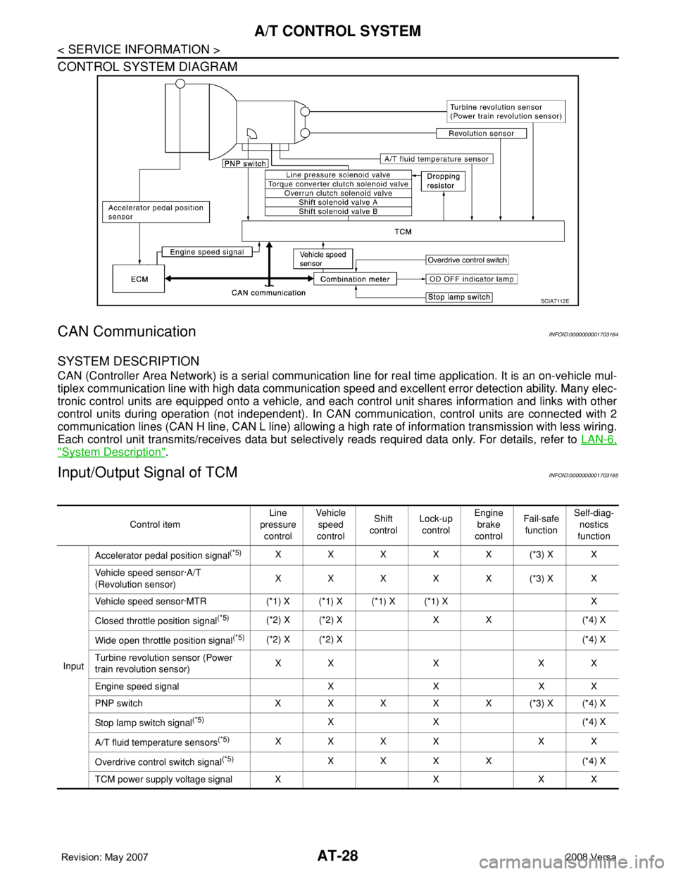
CONTROL SYSTEM DIAGRAM
CAN CommunicationINFOID:0000000001703164
SYSTEM DESCRIPTION
CAN (Controller Area Network) is a serial communication line for real time application. It is an on-vehicle mul-
tiplex communication line with high data communication speed and excellent error detection ability. Many elec-
tronic control units are equipped onto a vehicle, and each control unit shares information and links with other
control units during operation (not independent). In CAN communication, control units are connected with 2
communication lines (CAN H line, CAN L line) allowing a high rate of information transmission with less wiring.
Each control unit transmits/receives data but selectively reads required data only. For details, refer to LAN-6,
"System Description".
Input/Output Signal of TCMINFOID:0000000001703165
SCIA7112E
Control itemLine
pressure
controlVehicle
speed
controlShift
controlLock-up
controlEngine
brake
controlFail-safe
functionSelf-diag-
nostics
function
InputAccelerator pedal position signal
(*5)XXXXX(*3) XX
Vehicle speed sensor·A/T
(Revolution sensor)XXXXX(*3) XX
Vehicle speed sensor·MTR (*1) X (*1) X (*1) X (*1) X X
Closed throttle position signal
(*5)(*2) X (*2) X X X (*4) X
Wide open throttle position signal
(*5)(*2) X (*2) X (*4) X
Turbine revolution sensor (Power
train revolution sensor)XXXXX
Engine speed signal X X X X
PNP switch XXXXX(*3) X(*4) X
Stop lamp switch signal
(*5)XX (*4) X
A/T fluid temperature sensors
(*5)XXXX XX
Overdrive control switch signal
(*5)XXXX (*4) X
TCM power supply voltage signal X X X X
Page 41 of 2771
A/T CONTROL SYSTEM
AT-29
< SERVICE INFORMATION >
D
E
F
G
H
I
J
K
L
MA
B
AT
N
O
P
*1: Spare for vehicle speed sensor·A/T (revolution sensor)
*2: Spare for accelerator pedal position signal
*3: If these input and output signals are different, the TCM triggers the fail-safe function.
*4: Used as a condition for starting self-diagnostics; if self-diagnosis are not started, it is judged that there is some kind of error.
*5: Input by CAN communications.
*6: Output by CAN communications.
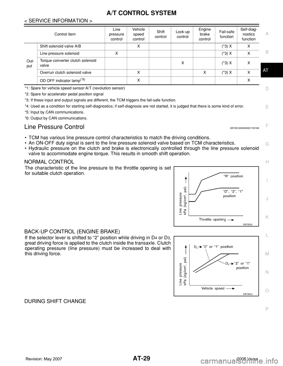
Line Pressure ControlINFOID:0000000001703166
• TCM has various line pressure control characteristics to match the driving conditions.
• An ON-OFF duty signal is sent to the line pressure solenoid valve based on TCM characteristics.
• Hydraulic pressure on the clutch and brake is electronically controlled through the line pressure solenoid
valve to accommodate engine torque. This results in smooth shift operation.
NORMAL CONTROL
The characteristic of the line pressure to the throttle opening is set
for suitable clutch operation.
BACK-UP CONTROL (ENGINE BRAKE)
If the selector lever is shifted to “2” position while driving in D4 or D3,
great driving force is applied to the clutch inside the transaxle. Clutch
operating pressure (line pressure) must be increased to deal with
this driving force.
DURING SHIFT CHANGE
Out-
putShift solenoid valve A/B X (*3) X X
Line pressure solenoid X (*3) X X
Torque converter clutch solenoid
valveX(*3) XX
Overrun clutch solenoid valve X X (*3) X X
OD OFF indicator lamp
(*6)XX Control itemLine
pressure
controlVeh icl e
speed
controlShift
controlLock-up
controlEngine
brake
controlFail-safe
functionSelf-diag-
nostics
function
SAT003J
SAT004J
Page 42 of 2771
AT-30
< SERVICE INFORMATION >
A/T CONTROL SYSTEM
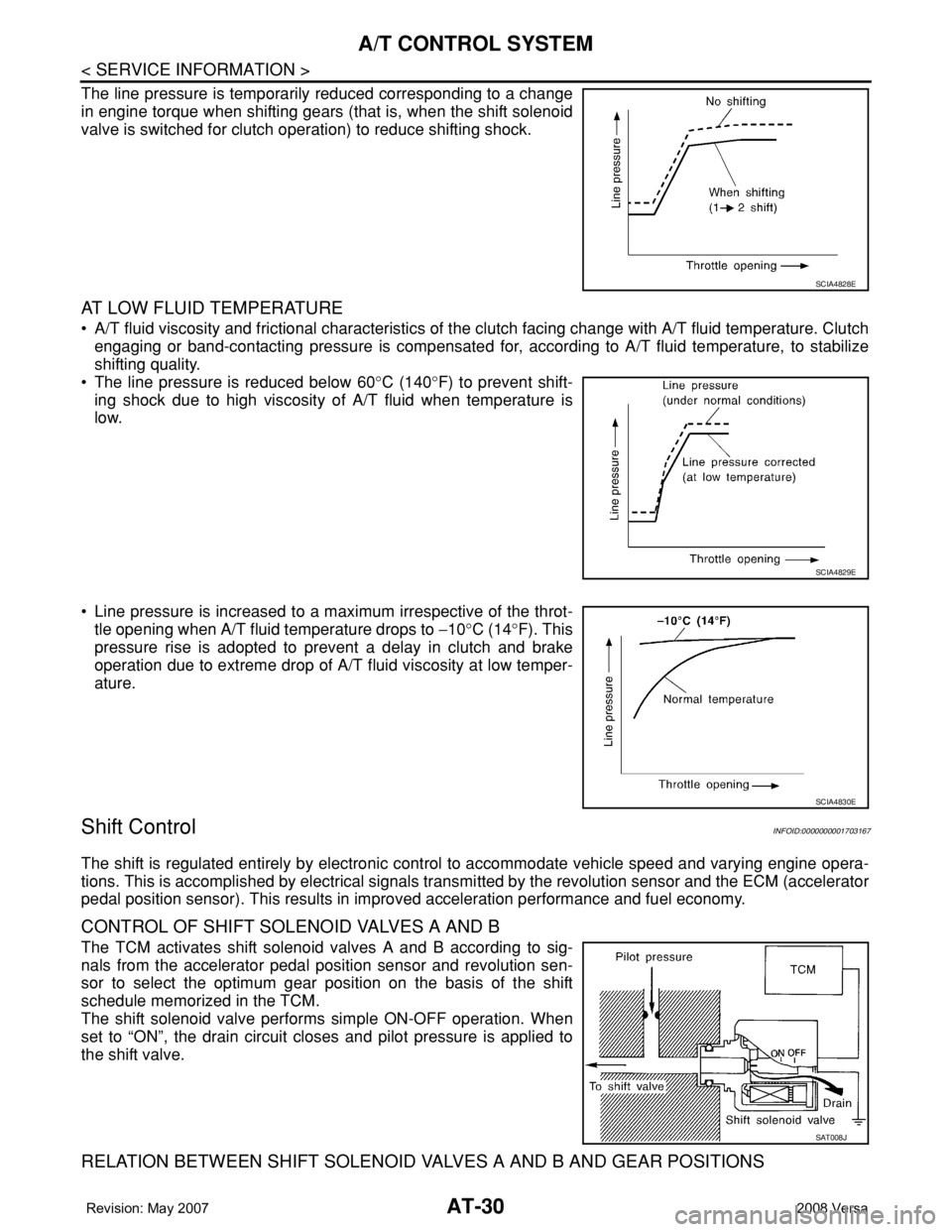
The line pressure is temporarily reduced corresponding to a change
in engine torque when shifting gears (that is, when the shift solenoid
valve is switched for clutch operation) to reduce shifting shock.
AT LOW FLUID TEMPERATURE
• A/T fluid viscosity and frictional characteristics of the clutch facing change with A/T fluid temperature. Clutch
engaging or band-contacting pressure is compensated for, according to A/T fluid temperature, to stabilize
shifting quality.
• The line pressure is reduced below 60°C (140°F) to prevent shift-
ing shock due to high viscosity of A/T fluid when temperature is
low.
• Line pressure is increased to a maximum irrespective of the throt-
tle opening when A/T fluid temperature drops to −10°C (14°F). This
pressure rise is adopted to prevent a delay in clutch and brake
operation due to extreme drop of A/T fluid viscosity at low temper-
ature.
Shift ControlINFOID:0000000001703167
The shift is regulated entirely by electronic control to accommodate vehicle speed and varying engine opera-
tions. This is accomplished by electrical signals transmitted by the revolution sensor and the ECM (accelerator
pedal position sensor). This results in improved acceleration performance and fuel economy.
CONTROL OF SHIFT SOLENOID VALVES A AND B
The TCM activates shift solenoid valves A and B according to sig-
nals from the accelerator pedal position sensor and revolution sen-
sor to select the optimum gear position on the basis of the shift
schedule memorized in the TCM.
The shift solenoid valve performs simple ON-OFF operation. When
set to “ON”, the drain circuit closes and pilot pressure is applied to
the shift valve.
RELATION BETWEEN SHIFT SOLENOID VALVES A AND B AND GEAR POSITIONS
SCIA4828E
SCIA4829E
SCIA4830E
SAT008J
Page 52 of 2771
AT-40
< SERVICE INFORMATION >
TROUBLE DIAGNOSIS
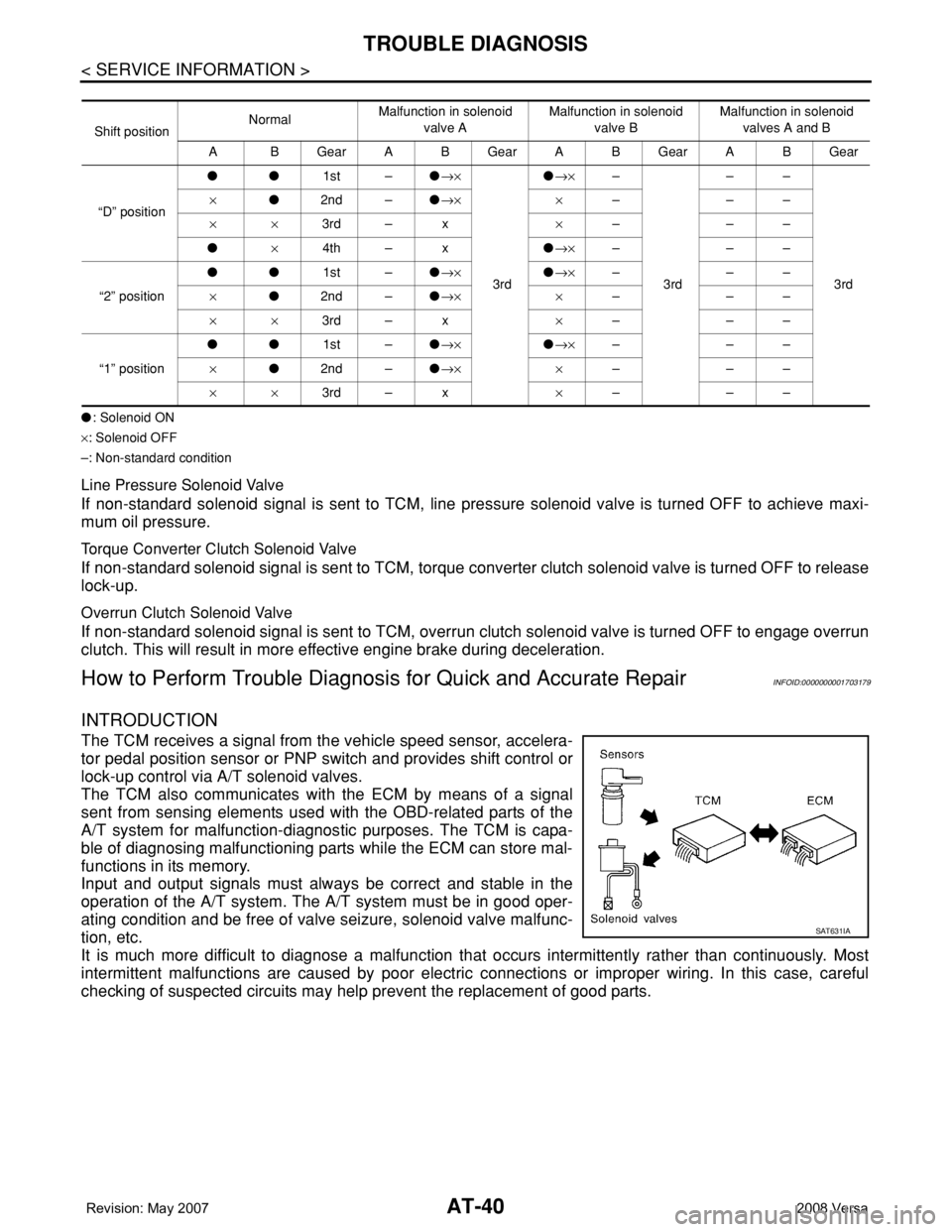
●: Solenoid ON
×: Solenoid OFF
–: Non-standard condition
Line Pressure Solenoid Valve
If non-standard solenoid signal is sent to TCM, line pressure solenoid valve is turned OFF to achieve maxi-
mum oil pressure.
Torque Converter Clutch Solenoid Valve
If non-standard solenoid signal is sent to TCM, torque converter clutch solenoid valve is turned OFF to release
lock-up.
Overrun Clutch Solenoid Valve
If non-standard solenoid signal is sent to TCM, overrun clutch solenoid valve is turned OFF to engage overrun
clutch. This will result in more effective engine brake during deceleration.
How to Perform Trouble Diagnosis for Quick and Accurate RepairINFOID:0000000001703179
INTRODUCTION
The TCM receives a signal from the vehicle speed sensor, accelera-
tor pedal position sensor or PNP switch and provides shift control or
lock-up control via A/T solenoid valves.
The TCM also communicates with the ECM by means of a signal
sent from sensing elements used with the OBD-related parts of the
A/T system for malfunction-diagnostic purposes. The TCM is capa-
ble of diagnosing malfunctioning parts while the ECM can store mal-
functions in its memory.
Input and output signals must always be correct and stable in the
operation of the A/T system. The A/T system must be in good oper-
ating condition and be free of valve seizure, solenoid valve malfunc-
tion, etc.
It is much more difficult to diagnose a malfunction that occurs intermittently rather than continuously. Most
intermittent malfunctions are caused by poor electric connections or improper wiring. In this case, careful
checking of suspected circuits may help prevent the replacement of good parts.
Shift positionNormalMalfunction in solenoid
valve AMalfunction in solenoid
valve BMalfunction in solenoid
valves A and B
A B Gear A B Gear A B Gear A B Gear
“D” position●●1st –●→×
3rd ●→×–
3rd ––
3rd ×●2nd –●→× ×–––
××3rd – x×–––
●×4th – x●→×–––
“2” position●●1st –●→×●→×–––
×●2nd –●→× ×–––
××3rd – x×–––
“1” position●●1st –●→×●→×–––
×●2nd –●→× ×–––
××3rd – x×–––
SAT631IA
Page 64 of 2771
AT-52
< SERVICE INFORMATION >
TROUBLE DIAGNOSIS
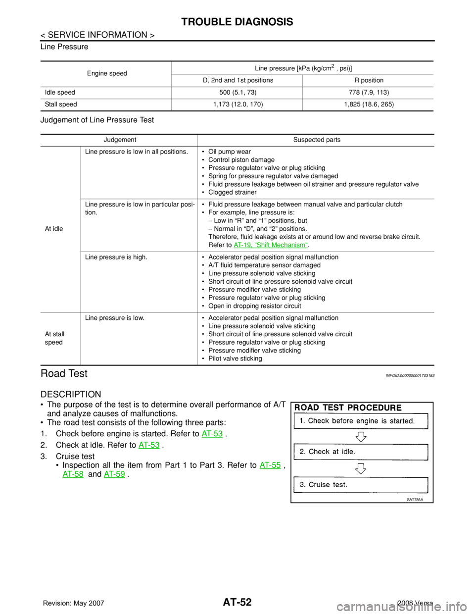
Line Pressure
Judgement of Line Pressure Test
Road TestINFOID:0000000001703183
DESCRIPTION
• The purpose of the test is to determine overall performance of A/T
and analyze causes of malfunctions.
• The road test consists of the following three parts:
1. Check before engine is started. Refer to AT- 5 3
.
2. Check at idle. Refer to AT- 5 3
.
3. Cruise test
• Inspection all the item from Part 1 to Part 3. Refer to AT- 5 5
,
AT- 5 8
and AT- 5 9 .
Engine speedLine pressure [kPa (kg/cm
2 , psi)]
D, 2nd and 1st positions R position
Idle speed 500 (5.1, 73) 778 (7.9, 113)
Stall speed 1,173 (12.0, 170) 1,825 (18.6, 265)
Judgement Suspected parts
At idleLine pressure is low in all positions. • Oil pump wear
• Control piston damage
• Pressure regulator valve or plug sticking
• Spring for pressure regulator valve damaged
• Fluid pressure leakage between oil strainer and pressure regulator valve
• Clogged strainer
Line pressure is low in particular posi-
tion.• Fluid pressure leakage between manual valve and particular clutch
• For example, line pressure is:
− Low in “R” and “1” positions, but
− Normal in “D”, and “2” positions.
Therefore, fluid leakage exists at or around low and reverse brake circuit.
Refer to AT- 1 9 , "
Shift Mechanism".
Line pressure is high. • Accelerator pedal position signal malfunction
• A/T fluid temperature sensor damaged
• Line pressure solenoid valve sticking
• Short circuit of line pressure solenoid valve circuit
• Pressure modifier valve sticking
• Pressure regulator valve or plug sticking
• Open in dropping resistor circuit
At stall
speedLine pressure is low. • Accelerator pedal position signal malfunction
• Line pressure solenoid valve sticking
• Short circuit of line pressure solenoid valve circuit
• Pressure regulator valve or plug sticking
• Pressure modifier valve sticking
• Pilot valve sticking
SAT786A