2008 NISSAN LATIO ECU
[x] Cancel search: ECUPage 2011 of 2771
![NISSAN LATIO 2008 Service Repair Manual LAN-20
< HOW TO USE THIS MANUAL >[CAN]
HOW TO USE THIS SECTION
HOW TO USE THIS MANUAL
HOW TO USE THIS SECTION
CautionINFOID:0000000001711213
• This section describes information peculiar to a vehicl NISSAN LATIO 2008 Service Repair Manual LAN-20
< HOW TO USE THIS MANUAL >[CAN]
HOW TO USE THIS SECTION
HOW TO USE THIS MANUAL
HOW TO USE THIS SECTION
CautionINFOID:0000000001711213
• This section describes information peculiar to a vehicl](/manual-img/5/57360/w960_57360-2010.png)
LAN-20
< HOW TO USE THIS MANUAL >[CAN]
HOW TO USE THIS SECTION
HOW TO USE THIS MANUAL
HOW TO USE THIS SECTION
CautionINFOID:0000000001711213
• This section describes information peculiar to a vehicle and inspection procedures.
• For trouble diagnosis procedure, refer to LAN-15, "
Trouble Diagnosis Procedure".
Abbreviation ListINFOID:0000000001711214
Unit name abbreviations in CONSULT-III CAN diagnosis and in this section are as per the following list.
Abbreviation Unit name
A-BAG Air bag diagnosis sensor unit
ABS ABS actuator and electric unit (control unit)
BCM BCM
DLC Data link connector
ECM ECM
EPS EPS control unit
I-KEY Intelligent Key unit
IPDM-E IPDM E/R
M&A Combination meter
TCM TCM
Page 2148 of 2771
HEADLAMP (FOR USA)
LT-11
< SERVICE INFORMATION >
C
D
E
F
G
H
I
J
L
MA
B
LT
N
O
P
How to Perform Trouble DiagnosisINFOID:0000000001704367
1. Confirm the symptom or customer complaint.
2. Understand operation, description and function description. Refer to LT- 4 , "
System Description" .
3. Perform the Preliminary Check. Refer to LT- 11 , "
Preliminary Check" .
4. Check symptom and repair or replace the cause of the malfunction.
5. Do the headlamps operate normally? If YES, GO TO 6. If NO, GO TO 4.
6. INSPECTION END
Preliminary CheckINFOID:0000000001704368
CHECK POWER SUPPLY AND GROUND CIRCUIT FOR BCM
Refer to BCS-15, "BCM Power Supply and Ground Circuit Inspection" .
CHECK POWER SUPPLY AND GROUND CIRCUIT FOR IPDM E/R
Refer to PG-25, "IPDM E/R Power/Ground Circuit Inspection" .
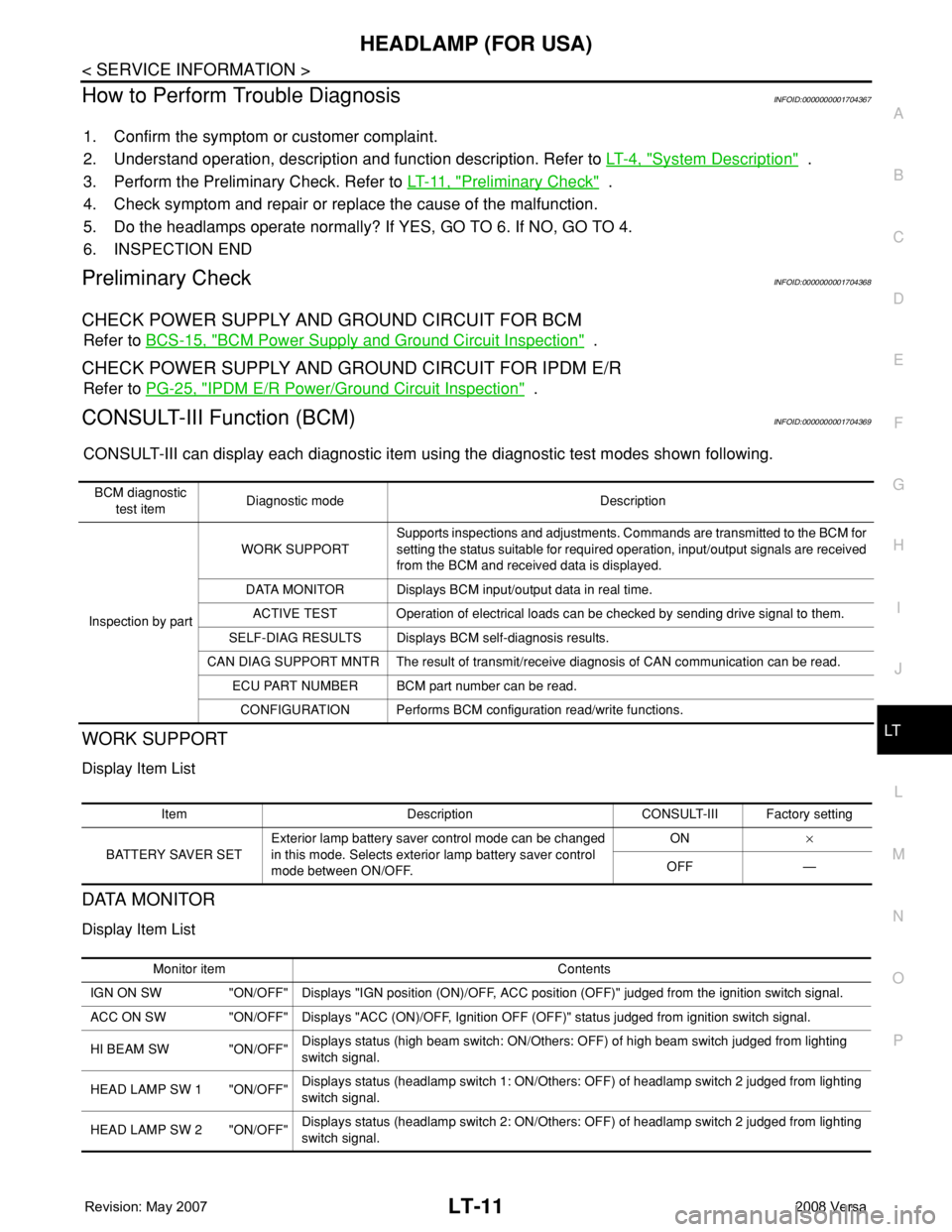
CONSULT-III Function (BCM)INFOID:0000000001704369
CONSULT-III can display each diagnostic item using the diagnostic test modes shown following.
WORK SUPPORT
Display Item List
DATA MONITOR
Display Item List
BCM diagnostic
test itemDiagnostic mode Description
Inspection by partWORK SUPPORTSupports inspections and adjustments. Commands are transmitted to the BCM for
setting the status suitable for required operation, input/output signals are received
from the BCM and received data is displayed.
DATA MONITOR Displays BCM input/output data in real time.
ACTIVE TEST Operation of electrical loads can be checked by sending drive signal to them.
SELF-DIAG RESULTS Displays BCM self-diagnosis results.
CAN DIAG SUPPORT MNTR The result of transmit/receive diagnosis of CAN communication can be read.
ECU PART NUMBER BCM part number can be read.
CONFIGURATION Performs BCM configuration read/write functions.
Item Description CONSULT-III Factory setting
BATTERY SAVER SETExterior lamp battery saver control mode can be changed
in this mode. Selects exterior lamp battery saver control
mode between ON/OFF.ON×
OFF —
Monitor item Contents
IGN ON SW "ON/OFF" Displays "IGN position (ON)/OFF, ACC position (OFF)" judged from the ignition switch signal.
ACC ON SW "ON/OFF" Displays "ACC (ON)/OFF, Ignition OFF (OFF)" status judged from ignition switch signal.
HI BEAM SW "ON/OFF"Displays status (high beam switch: ON/Others: OFF) of high beam switch judged from lighting
switch signal.
HEAD LAMP SW 1 "ON/OFF"Displays status (headlamp switch 1: ON/Others: OFF) of headlamp switch 2 judged from lighting
switch signal.
HEAD LAMP SW 2 "ON/OFF"Displays status (headlamp switch 2: ON/Others: OFF) of headlamp switch 2 judged from lighting
switch signal.
Page 2159 of 2771
LT-22
< SERVICE INFORMATION >
HEADLAMP (FOR USA)
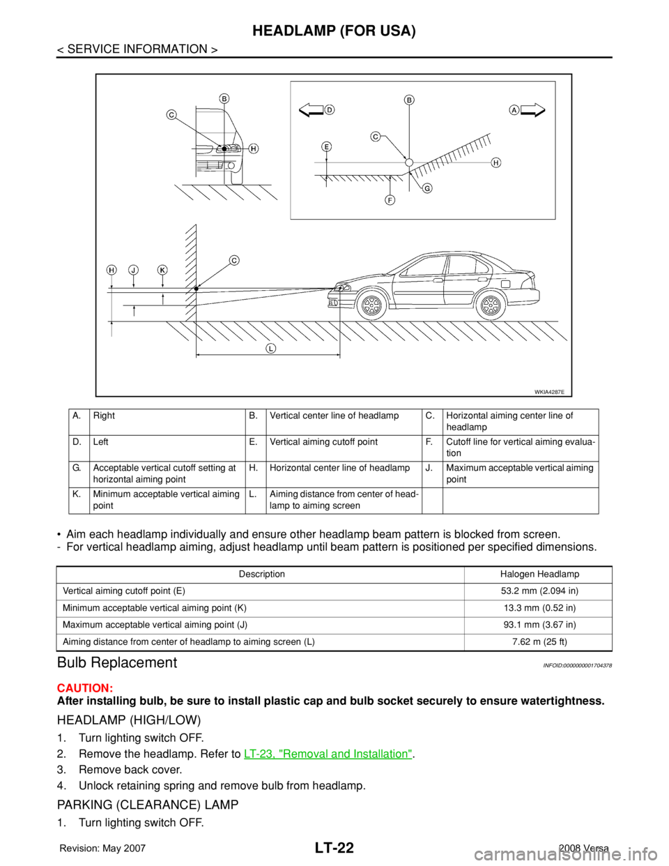
• Aim each headlamp individually and ensure other headlamp beam pattern is blocked from screen.
- For vertical headlamp aiming, adjust headlamp until beam pattern is positioned per specified dimensions.
Bulb ReplacementINFOID:0000000001704378
CAUTION:
After installing bulb, be sure to install plastic cap and bulb socket securely to ensure watertightness.
HEADLAMP (HIGH/LOW)
1. Turn lighting switch OFF.
2. Remove the headlamp. Refer to LT-23, "
Removal and Installation".
3. Remove back cover.
4. Unlock retaining spring and remove bulb from headlamp.
PARKING (CLEARANCE) LAMP
1. Turn lighting switch OFF.
A. Right B. Vertical center line of headlamp C. Horizontal aiming center line of
headlamp
D. Left E. Vertical aiming cutoff point F. Cutoff line for vertical aiming evalua-
tion
G. Acceptable vertical cutoff setting at
horizontal aiming pointH. Horizontal center line of headlamp J. Maximum acceptable vertical aiming
point
K. Minimum acceptable vertical aiming
pointL. Aiming distance from center of head-
lamp to aiming screen
WKIA4287E
Description Halogen Headlamp
Vertical aiming cutoff point (E)53.2 mm (2.094 in)
Minimum acceptable vertical aiming point (K) 13.3 mm (0.52 in)
Maximum acceptable vertical aiming point (J) 93.1 mm (3.67 in)
Aiming distance from center of headlamp to aiming screen (L) 7.62 m (25 ft)
Page 2161 of 2771

LT-24
< SERVICE INFORMATION >
HEADLAMP (FOR USA)
DISASSEMBLY
1. Remove back cover.
2. Unlock retaining spring and remove bulb (High/Low).
3. Turn parking (clearance) lamp bulb socket counterclockwise and unlock it.
4. Remove parking (clearance) lamp bulb from its socket.
5. Turn front turn signal lamp bulb socket counterclockwise and unlock it.
6. Remove front turn signal lamp bulb from its socket.
7. Remove the bumper stay.
ASSEMBLY
Assembly is in the reverse order of disassembly.
CAUTION:
• After installing bulb, be sure to install plastic cap securely to insure water tight seal.
1. Retaining spring 2. Parking (clearance) lamp bulb 3. Parking (clearance) lamp bulb socket
4. Halogen bulb (High/Low) 5. Back cover 6. Front turn signal lamp bulb socket
7. Front turn signal lamp bulb 8. Headlamp housing assembly 9. Bumper stay
A. Screw
Page 2173 of 2771
LT-36
< SERVICE INFORMATION >
HEADLAMP (FOR CANADA) - DAYTIME LIGHT SYSTEM -
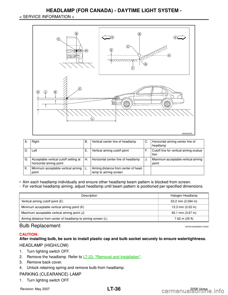
• Aim each headlamp individually and ensure other headlamp beam pattern is blocked from screen.
- For vertical headlamp aiming, adjust headlamp until beam pattern is positioned per specified dimensions.
Bulb ReplacementINFOID:0000000001704394
CAUTION:
After installing bulb, be sure to install plastic cap and bulb socket securely to ensure watertightness.
HEADLAMP (HIGH/LOW)
1. Turn lighting switch OFF.
2. Remove the headlamp. Refer to LT-23, "
Removal and Installation".
3. Remove back cover.
4. Unlock retaining spring and remove bulb from headlamp.
PARKING (CLEARANCE) LAMP
1. Turn lighting switch OFF.
A. Right B. Vertical center line of headlamp C. Horizontal aiming center line of
headlamp
D. Left E. Vertical aiming cutoff point F. Cutoff line for vertical aiming evalua-
tion
G. Acceptable vertical cutoff setting at
horizontal aiming pointH. Horizontal center line of headlamp J. Maximum acceptable vertical aiming
point
K. Minimum acceptable vertical aiming
pointL. Aiming distance from center of head-
lamp to aiming screen
WKIA4287E
Description Halogen Headlamp
Vertical aiming cutoff point (E)53.2 mm (2.094 in)
Minimum acceptable vertical aiming point (K) 13.3 mm (0.52 in)
Maximum acceptable vertical aiming point (J) 93.1 mm (3.67 in)
Aiming distance from center of headlamp to aiming screen (L) 7.62 m (25 ft)
Page 2175 of 2771

LT-38
< SERVICE INFORMATION >
HEADLAMP (FOR CANADA) - DAYTIME LIGHT SYSTEM -
DISASSEMBLY
1. Remove back cover.
2. Unlock retaining spring and remove bulb (High/Low).
3. Turn parking (clearance) lamp bulb socket counterclockwise and unlock it.
4. Remove parking (clearance) lamp bulb from its socket.
5. Turn front turn signal lamp bulb socket counterclockwise and unlock it.
6. Remove front turn signal lamp bulb from its socket.
7. Remove the bumper stay.
ASSEMBLY
Assembly is in the reverse order of disassembly.
CAUTION:
• After installing bulb, be sure to install plastic cap securely to insure water tight seal.
1. Retaining spring 2. Parking (clearance) lamp bulb 3. Parking (clearance) lamp bulb socket
4. Halogen bulb (High/Low) 5. Back cover 6. Front turn signal lamp bulb socket
7. Front turn signal lamp bulb 8. Headlamp housing assembly 9. Bumper stay
A. Screw
Page 2256 of 2771
LU-6
< SERVICE INFORMATION >
ENGINE OIL
ENGINE OIL
InspectionINFOID:0000000001702518
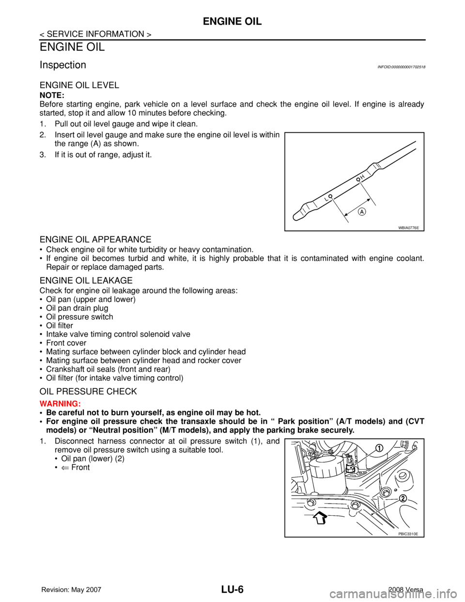
ENGINE OIL LEVEL
NOTE:
Before starting engine, park vehicle on a level surface and check the engine oil level. If engine is already
started, stop it and allow 10 minutes before checking.
1. Pull out oil level gauge and wipe it clean.
2. Insert oil level gauge and make sure the engine oil level is within
the range (A) as shown.
3. If it is out of range, adjust it.
ENGINE OIL APPEARANCE
• Check engine oil for white turbidity or heavy contamination.
• If engine oil becomes turbid and white, it is highly probable that it is contaminated with engine coolant.
Repair or replace damaged parts.
ENGINE OIL LEAKAGE
Check for engine oil leakage around the following areas:
• Oil pan (upper and lower)
• Oil pan drain plug
• Oil pressure switch
• Oil filter
• Intake valve timing control solenoid valve
• Front cover
• Mating surface between cylinder block and cylinder head
• Mating surface between cylinder head and rocker cover
• Crankshaft oil seals (front and rear)
• Oil filter (for intake valve timing control)
OIL PRESSURE CHECK
WARNING:
• Be careful not to burn yourself, as engine oil may be hot.
• For engine oil pressure check the transaxle should be in “ Park position” (A/T models) and (CVT
models) or “Neutral position” (M/T models), and apply the parking brake securely.
1. Disconnect harness connector at oil pressure switch (1), and
remove oil pressure switch using a suitable tool.
• Oil pan (lower) (2)
•⇐ Front
WBIA0776E
PBIC3310E
Page 2264 of 2771
MA-4
< SERVICE INFORMATION >
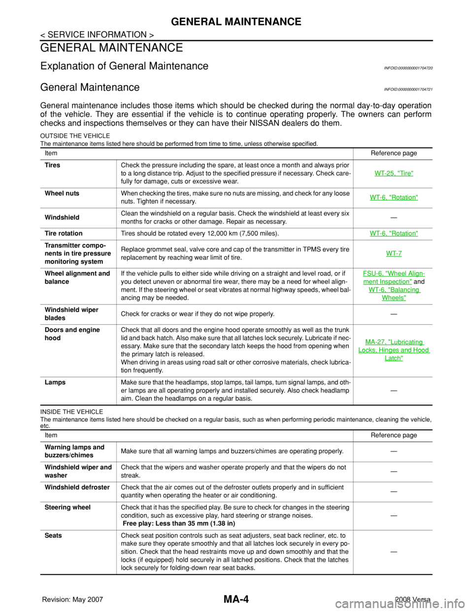
GENERAL MAINTENANCE
GENERAL MAINTENANCE
Explanation of General MaintenanceINFOID:0000000001704720
General MaintenanceINFOID:0000000001704721
General maintenance includes those items which should be checked during the normal day-to-day operation
of the vehicle. They are essential if the vehicle is to continue operating properly. The owners can perform
checks and inspections themselves or they can have their NISSAN dealers do them.
OUTSIDE THE VEHICLE
The maintenance items listed here should be performed from time to time, unless otherwise specified.
INSIDE THE VEHICLE
The maintenance items listed here should be checked on a regular basis, such as when performing periodic maintenance, cleaning the vehicle,
etc.
ItemReference page
TiresCheck the pressure including the spare, at least once a month and always prior
to a long distance trip. Adjust to the specified pressure if necessary. Check care-
fully for damage, cuts or excessive wear.WT-25, "
Tire"
Wheel nutsWhen checking the tires, make sure no nuts are missing, and check for any loose
nuts. Tighten if necessary.WT-6, "Rotation"
WindshieldClean the windshield on a regular basis. Check the windshield at least every six
months for cracks or other damage. Repair as necessary.—
Tire rotationTires should be rotated every 12,000 km (7,500 miles).WT-6, "
Rotation"
Transmitter compo-
nents in tire pressure
monitoring systemReplace grommet seal, valve core and cap of the transmitter in TPMS every tire
replacement by reaching wear limit of tire.WT-7
Wheel alignment and
balanceIf the vehicle pulls to either side while driving on a straight and level road, or if
you detect uneven or abnormal tire wear, there may be a need for wheel align-
ment. If the steering wheel or seat vibrates at normal highway speeds, wheel bal-
ancing may be needed.FSU-6, "Wheel Align-
ment Inspection" and
WT-6, "
Balancing
Wheels"
Windshield wiper
bladesCheck for cracks or wear if they do not wipe properly. —
Doors and engine
hoodCheck that all doors and the engine hood operate smoothly as well as the trunk
lid and back hatch. Also make sure that all latches lock securely. Lubricate if nec-
essary. Make sure that the secondary latch keeps the hood from opening when
the primary latch is released.
When driving in areas using road salt or other corrosive materials, check lubrica-
tion frequently.MA-27, "
Lubricating
Locks, Hinges and Hood
Latch"
LampsMake sure that the headlamps, stop lamps, tail lamps, turn signal lamps, and oth-
er lamps are all operating properly and installed securely. Also check headlamp
aim. Clean the headlamps on a regular basis.—
ItemReference page
Warning lamps and
buzzers/chimesMake sure that all warning lamps and buzzers/chimes are operating properly. —
Windshield wiper and
washerCheck that the wipers and washer operate properly and that the wipers do not
streak.—
Windshield defrosterCheck that the air comes out of the defroster outlets properly and in sufficient
quantity when operating the heater or air conditioning.—
Steering wheelCheck that it has the specified play. Be sure to check for changes in the steering
condition, such as excessive play, hard steering or strange noises.
Free play: Less than 35 mm (1.38 in)—
SeatsCheck seat position controls such as seat adjusters, seat back recliner, etc. to
make sure they operate smoothly and that all latches lock securely in every po-
sition. Check that the head restraints move up and down smoothly and that the
locks (if equipped) hold securely in all latched positions. Check that the latches
lock securely for folding-down rear seat backs.—