Page 1818 of 2771
FAX-22
< SERVICE INFORMATION >
FRONT DRIVE SHAFT
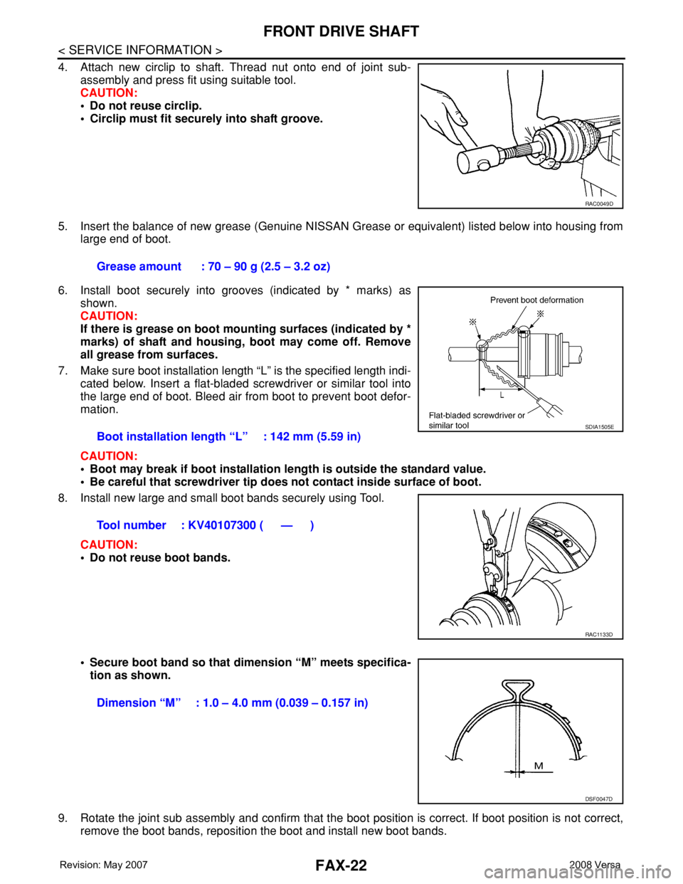
4. Attach new circlip to shaft. Thread nut onto end of joint sub-
assembly and press fit using suitable tool.
CAUTION:
• Do not reuse circlip.
• Circlip must fit securely into shaft groove.
5. Insert the balance of new grease (Genuine NISSAN Grease or equivalent) listed below into housing from
large end of boot.
6. Install boot securely into grooves (indicated by * marks) as
shown.
CAUTION:
If there is grease on boot mounting surfaces (indicated by *
marks) of shaft and housing, boot may come off. Remove
all grease from surfaces.
7. Make sure boot installation length “L” is the specified length indi-
cated below. Insert a flat-bladed screwdriver or similar tool into
the large end of boot. Bleed air from boot to prevent boot defor-
mation.
CAUTION:
• Boot may break if boot installation length is outside the standard value.
• Be careful that screwdriver tip does not contact inside surface of boot.
8. Install new large and small boot bands securely using Tool.
CAUTION:
• Do not reuse boot bands.
• Secure boot band so that dimension “M” meets specifica-
tion as shown.
9. Rotate the joint sub assembly and confirm that the boot position is correct. If boot position is not correct,
remove the boot bands, reposition the boot and install new boot bands.
RAC0049D
Grease amount : 70 – 90 g (2.5 – 3.2 oz)
Boot installation length “L” : 142 mm (5.59 in)
Tool number : KV40107300 ( — )
SDIA1505E
RAC1133D
Dimension “M” : 1.0 – 4.0 mm (0.039 – 0.157 in)
DSF0047D
Page 1819 of 2771
FRONT DRIVE SHAFT
FAX-23
< SERVICE INFORMATION >
C
E
F
G
H
I
J
K
L
MA
B
FA X
N
O
P Support Bearing
1. Install new dust shield on drive shaft
CAUTION:
Do not reuse dust shield.
2. Press support bearing onto drive shaft.
3. Install new snap ring.
CAUTION:
Do not reuse snap ring.
4. Install new dust shield
CAUTION:
Do not reuse dust shield.
Damper
1. Secure damper with new damper bands.
CAUTION:
Do not reuse damper bands.
YA X 0 0 7
YA X 0 0 8
“A”Except for CVT
models: 230 – 236 mm (9.06 – 9.29 in)
CVT models : 225 – 231 mm (8.86 – 9.09 in)
“B” : 70 mm (2.76 in)
FAC0156D
Page 1824 of 2771
FL-4
< SERVICE INFORMATION >
FUEL SYSTEM
FUEL SYSTEM
Checking Fuel LineINFOID:0000000001703097
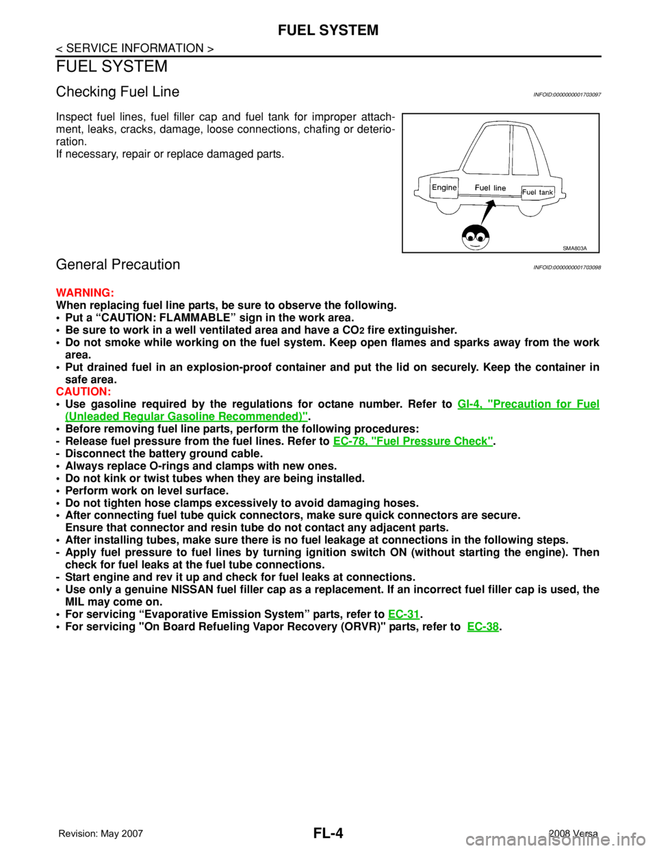
Inspect fuel lines, fuel filler cap and fuel tank for improper attach-
ment, leaks, cracks, damage, loose connections, chafing or deterio-
ration.
If necessary, repair or replace damaged parts.
General PrecautionINFOID:0000000001703098
WARNING:
When replacing fuel line parts, be sure to observe the following.
• Put a “CAUTION: FLAMMABLE” sign in the work area.
• Be sure to work in a well ventilated area and have a CO
2 fire extinguisher.
• Do not smoke while working on the fuel system. Keep open flames and sparks away from the work
area.
• Put drained fuel in an explosion-proof container and put the lid on securely. Keep the container in
safe area.
CAUTION:
• Use gasoline required by the regulations for octane number. Refer to GI-4, "
Precaution for Fuel
(Unleaded Regular Gasoline Recommended)".
• Before removing fuel line parts, perform the following procedures:
- Release fuel pressure from the fuel lines. Refer to EC-78, "
Fuel Pressure Check".
- Disconnect the battery ground cable.
• Always replace O-rings and clamps with new ones.
• Do not kink or twist tubes when they are being installed.
• Perform work on level surface.
• Do not tighten hose clamps excessively to avoid damaging hoses.
• After connecting fuel tube quick connectors, make sure quick connectors are secure.
Ensure that connector and resin tube do not contact any adjacent parts.
• After installing tubes, make sure there is no fuel leakage at connections in the following steps.
- Apply fuel pressure to fuel lines by turning ignition switch ON (without starting the engine). Then
check for fuel leaks at the fuel tube connections.
- Start engine and rev it up and check for fuel leaks at connections.
• Use only a genuine NISSAN fuel filler cap as a replacement. If an incorrect fuel filler cap is used, the
MIL may come on.
• For servicing “Evaporative Emission System” parts, refer to EC-31
.
• For servicing "On Board Refueling Vapor Recovery (ORVR)" parts, refer to EC-38
.
SMA803A
Page 1827 of 2771
FUEL LEVEL SENSOR UNIT, FUEL FILTER AND FUEL PUMP ASSEMBLY
FL-7
< SERVICE INFORMATION >
C
D
E
F
G
H
I
J
K
L
MA
FL
N
P O
Make sure that the fuel level sensor unit, fuel filter and fuel pump is free from defects and foreign materials.
INSTALLATION
Installation is in the reverse order of removal.
Fuel Level Sensor Unit, Fuel Filter and Fuel Pump Assembly
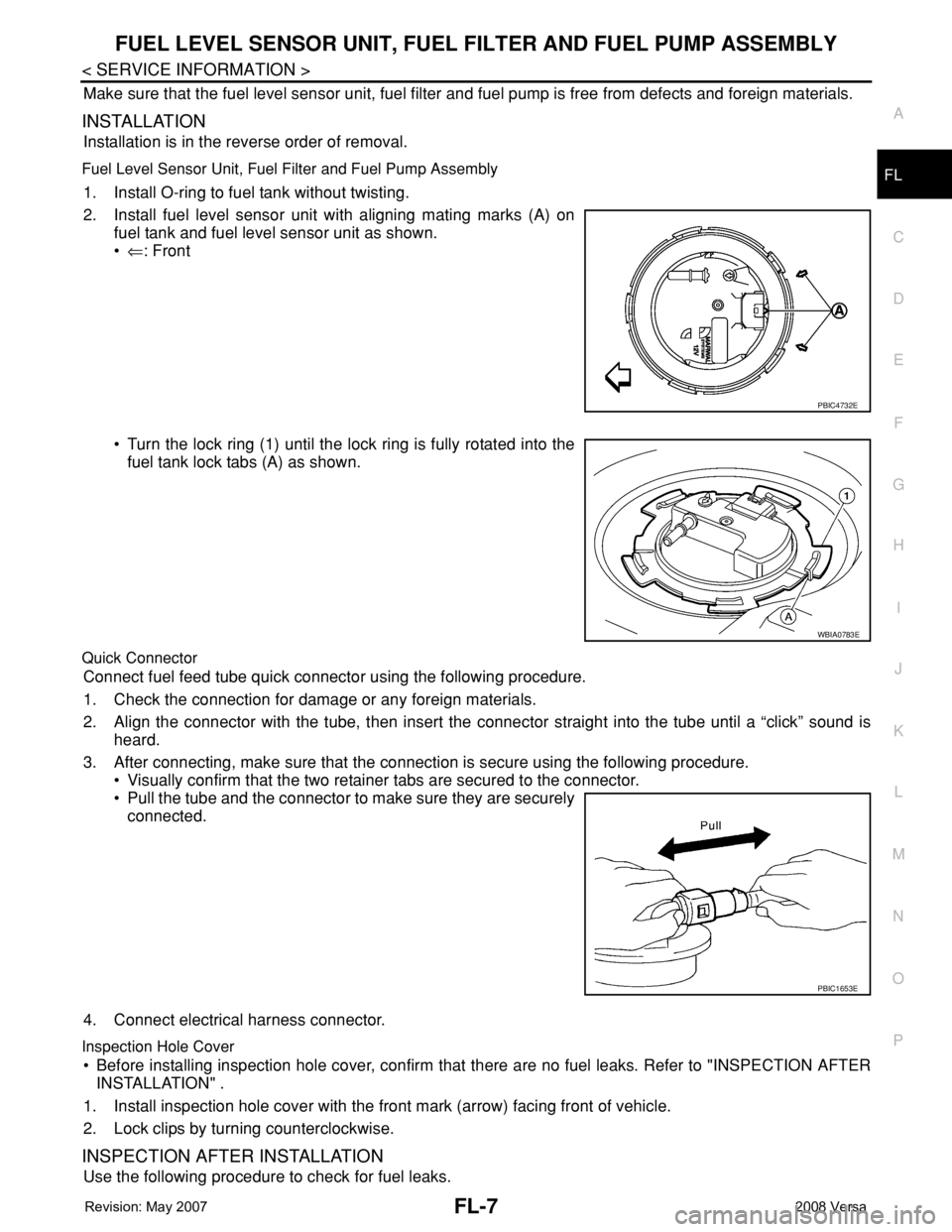
1. Install O-ring to fuel tank without twisting.
2. Install fuel level sensor unit with aligning mating marks (A) on
fuel tank and fuel level sensor unit as shown.
•⇐: Front
• Turn the lock ring (1) until the lock ring is fully rotated into the
fuel tank lock tabs (A) as shown.
Quick Connector
Connect fuel feed tube quick connector using the following procedure.
1. Check the connection for damage or any foreign materials.
2. Align the connector with the tube, then insert the connector straight into the tube until a “click” sound is
heard.
3. After connecting, make sure that the connection is secure using the following procedure.
• Visually confirm that the two retainer tabs are secured to the connector.
• Pull the tube and the connector to make sure they are securely
connected.
4. Connect electrical harness connector.
Inspection Hole Cover
• Before installing inspection hole cover, confirm that there are no fuel leaks. Refer to "INSPECTION AFTER
INSTALLATION" .
1. Install inspection hole cover with the front mark (arrow) facing front of vehicle.
2. Lock clips by turning counterclockwise.
INSPECTION AFTER INSTALLATION
Use the following procedure to check for fuel leaks.
PBIC4732E
WBIA0783E
PBIC1653E
Page 1832 of 2771
FL-12
< SERVICE INFORMATION >
FUEL TANK
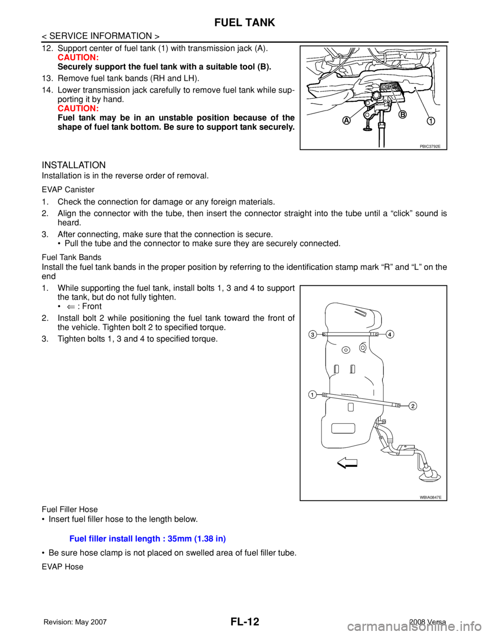
12. Support center of fuel tank (1) with transmission jack (A).
CAUTION:
Securely support the fuel tank with a suitable tool (B).
13. Remove fuel tank bands (RH and LH).
14. Lower transmission jack carefully to remove fuel tank while sup-
porting it by hand.
CAUTION:
Fuel tank may be in an unstable position because of the
shape of fuel tank bottom. Be sure to support tank securely.
INSTALLATION
Installation is in the reverse order of removal.
EVAP Canister
1. Check the connection for damage or any foreign materials.
2. Align the connector with the tube, then insert the connector straight into the tube until a “click” sound is
heard.
3. After connecting, make sure that the connection is secure.
• Pull the tube and the connector to make sure they are securely connected.
Fuel Tank Bands
Install the fuel tank bands in the proper position by referring to the identification stamp mark “R” and “L” on the
end
1. While supporting the fuel tank, install bolts 1, 3 and 4 to support
the tank, but do not fully tighten.
• ⇐ : Front
2. Install bolt 2 while positioning the fuel tank toward the front of
the vehicle. Tighten bolt 2 to specified torque.
3. Tighten bolts 1, 3 and 4 to specified torque.
Fuel Filler Hose
• Insert fuel filler hose to the length below.
• Be sure hose clamp is not placed on swelled area of fuel filler tube.
EVAP Hose
PBIC3792E
WBIA0847E
Fuel filler install length : 35mm (1.38 in)
Page 1833 of 2771
FUEL TANK
FL-13
< SERVICE INFORMATION >
C
D
E
F
G
H
I
J
K
L
MA
FL
N
P O
1. Check connections for damage or foreign material.
2. Align the matching quick connector (A) with the center of EVAP
hose (1), and insert quick connector (A) straight until it clicks.
3. After connecting, pull on quick connector (A) and EVAP hose (1)
by hand. Make sure connections are secure.
INSPECTION AFTER INSTALLATION
Use the following procedure to check for fuel leaks.
1. Turn ignition switch “ON” (without starting the engine), to check the connections for fuel leaks with the
electric fuel pump applying pressure to the fuel piping.
2. Start the engine and let it idle to check that there are no fuel leaks at the fuel system connections.
WBIA0767E
Page 1846 of 2771
FSU-12
< SERVICE INFORMATION >
COIL SPRING AND STRUT
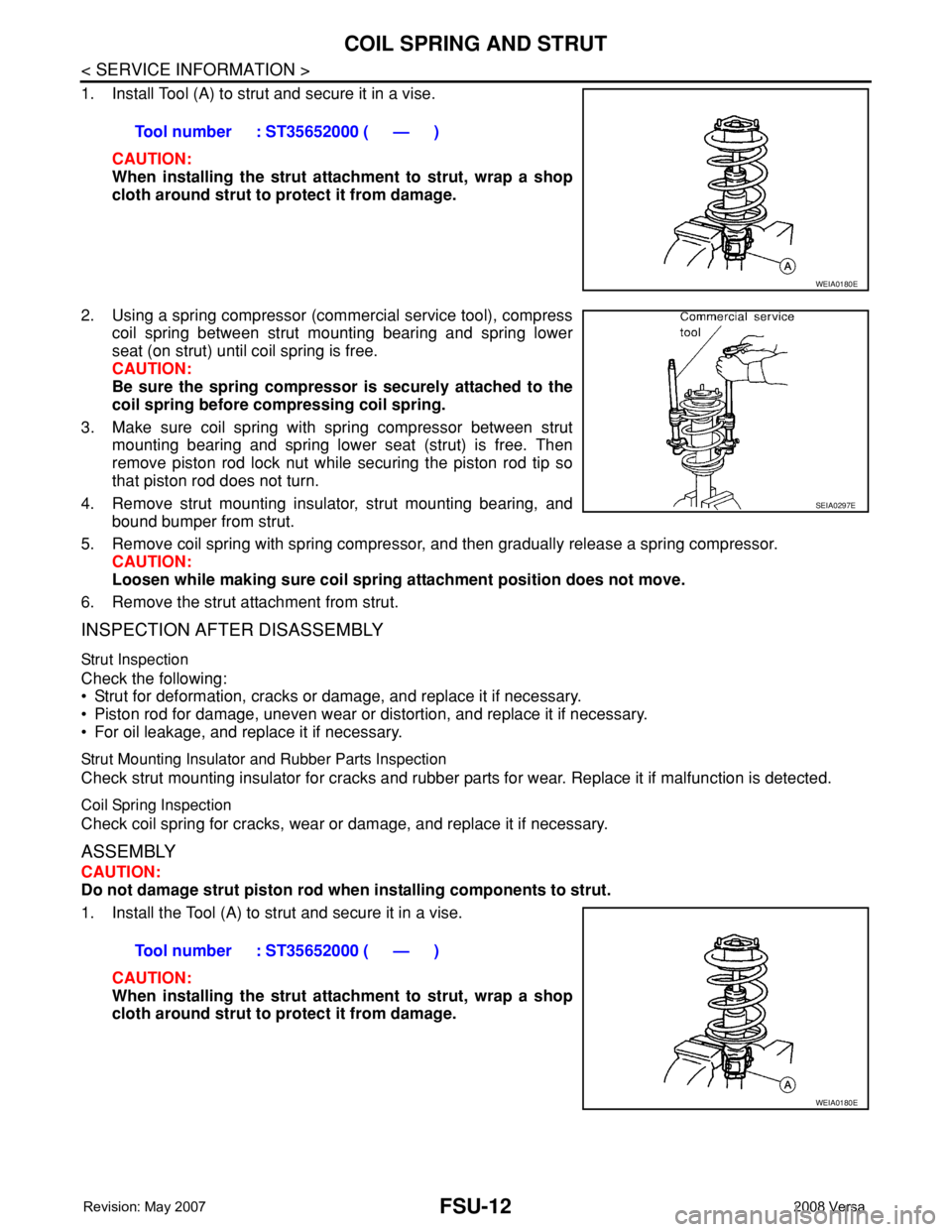
1. Install Tool (A) to strut and secure it in a vise.
CAUTION:
When installing the strut attachment to strut, wrap a shop
cloth around strut to protect it from damage.
2. Using a spring compressor (commercial service tool), compress
coil spring between strut mounting bearing and spring lower
seat (on strut) until coil spring is free.
CAUTION:
Be sure the spring compressor is securely attached to the
coil spring before compressing coil spring.
3. Make sure coil spring with spring compressor between strut
mounting bearing and spring lower seat (strut) is free. Then
remove piston rod lock nut while securing the piston rod tip so
that piston rod does not turn.
4. Remove strut mounting insulator, strut mounting bearing, and
bound bumper from strut.
5. Remove coil spring with spring compressor, and then gradually release a spring compressor.
CAUTION:
Loosen while making sure coil spring attachment position does not move.
6. Remove the strut attachment from strut.
INSPECTION AFTER DISASSEMBLY
Strut Inspection
Check the following:
• Strut for deformation, cracks or damage, and replace it if necessary.
• Piston rod for damage, uneven wear or distortion, and replace it if necessary.
• For oil leakage, and replace it if necessary.
Strut Mounting Insulator and Rubber Parts Inspection
Check strut mounting insulator for cracks and rubber parts for wear. Replace it if malfunction is detected.
Coil Spring Inspection
Check coil spring for cracks, wear or damage, and replace it if necessary.
ASSEMBLY
CAUTION:
Do not damage strut piston rod when installing components to strut.
1. Install the Tool (A) to strut and secure it in a vise.
CAUTION:
When installing the strut attachment to strut, wrap a shop
cloth around strut to protect it from damage.Tool number : ST35652000 ( — )
WEIA0180E
SEIA0297E
Tool number : ST35652000 ( — )
WEIA0180E
Page 1847 of 2771
COIL SPRING AND STRUT
FSU-13
< SERVICE INFORMATION >
C
D
F
G
H
I
J
K
L
MA
B
FSU
N
O
P
2. Compress coil spring using a spring compressor (commercial
service tool), and install it onto strut.
CAUTION:
• Face tube side of coil spring downward. Align the lower
end to spring lower seat as shown.
• Be sure spring compressor is securely attached to coil
spring. Compress coil spring.
3. Apply soapy water to bound bumper. Insert bound bumper into
strut mounting insulator.
CAUTION:
Do not use machine oil.
4. Attach strut mounting bearing and strut mounting insulator.
• Installation position of strut mounting insulator as shown.
5. Secure piston rod tip so that piston rod does not turn, then
tighten piston rod lock nut to specified torque.
6. Gradually release a spring compressor, and remove coil spring.
CAUTION:
Loosen while making sure coil spring attachment position
does not move.
7. Remove the strut attachment from strut.
SEIA0297E
MEIA0016E
MEIA0014E