2008 NISSAN LATIO ECU
[x] Cancel search: ECUPage 1856 of 2771
PRECAUTIONS
GI-5
< SERVICE INFORMATION >
C
D
E
F
G
H
I
J
K
L
MB
GI
N
O
P
Precaution for Multiport Fuel Injection System or Engine Control SystemINFOID:0000000001702427
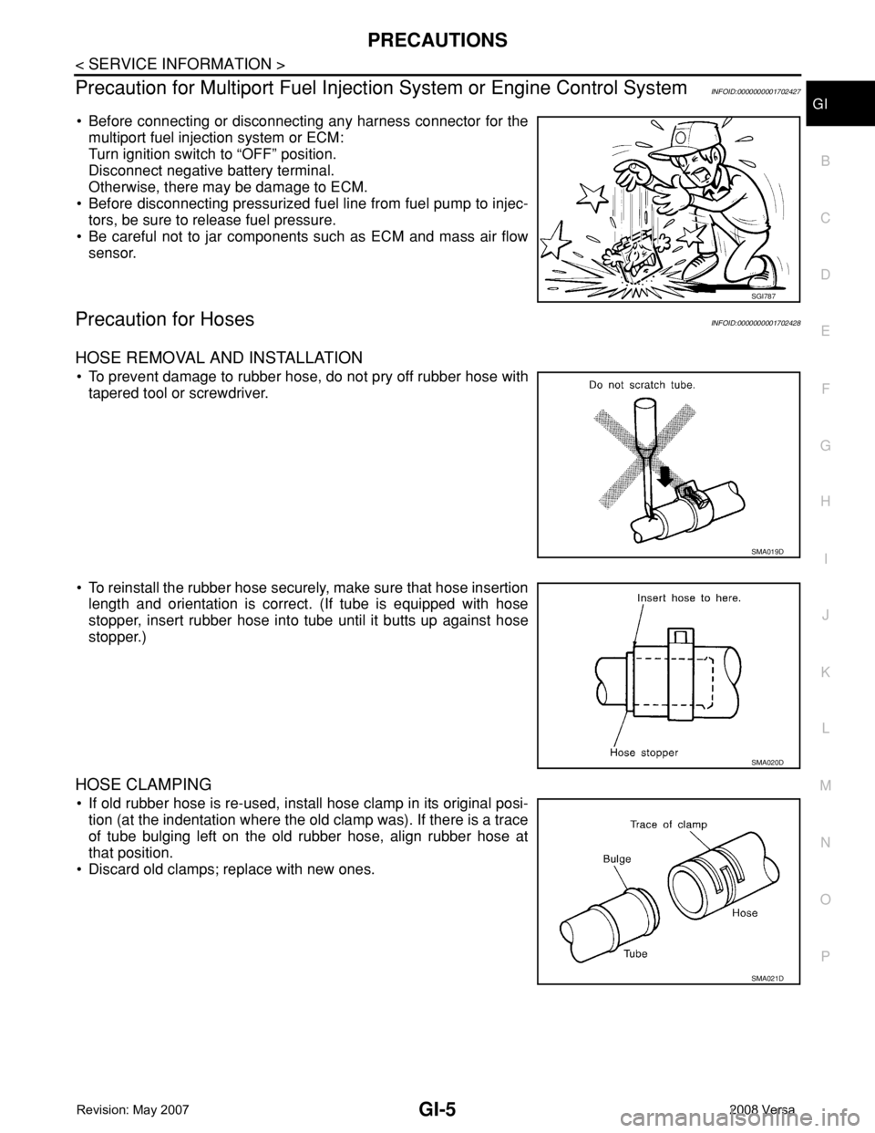
• Before connecting or disconnecting any harness connector for the
multiport fuel injection system or ECM:
Turn ignition switch to “OFF” position.
Disconnect negative battery terminal.
Otherwise, there may be damage to ECM.
• Before disconnecting pressurized fuel line from fuel pump to injec-
tors, be sure to release fuel pressure.
• Be careful not to jar components such as ECM and mass air flow
sensor.
Precaution for HosesINFOID:0000000001702428
HOSE REMOVAL AND INSTALLATION
• To prevent damage to rubber hose, do not pry off rubber hose with
tapered tool or screwdriver.
• To reinstall the rubber hose securely, make sure that hose insertion
length and orientation is correct. (If tube is equipped with hose
stopper, insert rubber hose into tube until it butts up against hose
stopper.)
HOSE CLAMPING
• If old rubber hose is re-used, install hose clamp in its original posi-
tion (at the indentation where the old clamp was). If there is a trace
of tube bulging left on the old rubber hose, align rubber hose at
that position.
• Discard old clamps; replace with new ones.
SGI787
SMA019D
SMA020D
SMA021D
Page 1881 of 2771
GI-30
< SERVICE INFORMATION >
SERVICE INFORMATION FOR ELECTRICAL INCIDENT
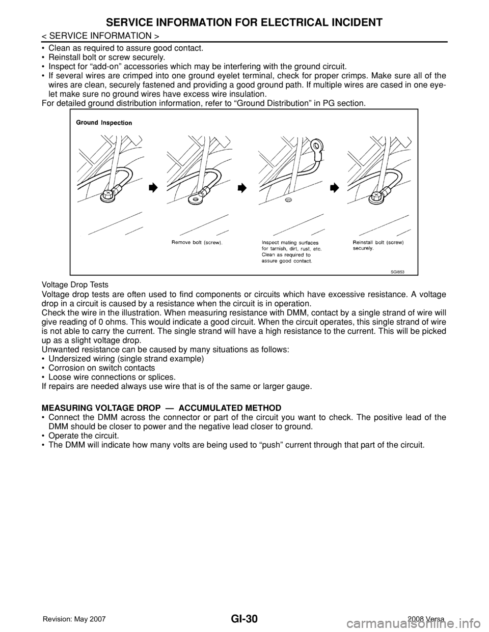
• Clean as required to assure good contact.
• Reinstall bolt or screw securely.
• Inspect for “add-on” accessories which may be interfering with the ground circuit.
• If several wires are crimped into one ground eyelet terminal, check for proper crimps. Make sure all of the
wires are clean, securely fastened and providing a good ground path. If multiple wires are cased in one eye-
let make sure no ground wires have excess wire insulation.
For detailed ground distribution information, refer to “Ground Distribution” in PG section.
Voltage Drop Tests
Voltage drop tests are often used to find components or circuits which have excessive resistance. A voltage
drop in a circuit is caused by a resistance when the circuit is in operation.
Check the wire in the illustration. When measuring resistance with DMM, contact by a single strand of wire will
give reading of 0 ohms. This would indicate a good circuit. When the circuit operates, this single strand of wire
is not able to carry the current. The single strand will have a high resistance to the current. This will be picked
up as a slight voltage drop.
Unwanted resistance can be caused by many situations as follows:
• Undersized wiring (single strand example)
• Corrosion on switch contacts
• Loose wire connections or splices.
If repairs are needed always use wire that is of the same or larger gauge.
MEASURING VOLTAGE DROP — ACCUMULATED METHOD
• Connect the DMM across the connector or part of the circuit you want to check. The positive lead of the
DMM should be closer to power and the negative lead closer to ground.
• Operate the circuit.
• The DMM will indicate how many volts are being used to “push” current through that part of the circuit.
SGI853
Page 1886 of 2771

CONSULT-III CHECKING SYSTEM
GI-35
< SERVICE INFORMATION >
C
D
E
F
G
H
I
J
K
L
MB
GI
N
O
PCONSULT-III CHECKING SYSTEM
DescriptionINFOID:0000000001806209
• CONSULT-III is a hand-held type tester. When it is connected with a diagnostic connector equipped on the
vehicle side, it will communicate with the control unit equipped in the vehicle and then enable various kinds
of diagnostic tests.
• Refer to CONSULT-III Operator's Manual for more information.
Function and System ApplicationINFOID:0000000001806219
x: Applicable.
*1: If equipped.
*2: This option is shown on vehicles equipped with continuously variable transmission (CVT).
*3: NVIS (NATS) [NISSAN Vehicle Immobilizer System (Nissan Anti-theft System)]. Diagnostic test mode Function
ENGINE
ABS*
1
AIR BAG
EPS
IPDM E/R
BCM
METER/M&A
INTELLIGENT KEY*
1
A/T*
1
TRANSMISSION*
2
NVIS (NATS)*
3
NVIS (NATS BCM OR S/ENT)*
3
NATS I-KEY
*3,5
Work supportThis mode enables a technician to adjust some devices faster
and more accurately by following indications on CONSULT-III.x----x-xxx--x
Self-diagnostic results Self-diagnostic results can be read and erased quickly. xxxxxxxxxxx - x
Trouble diagnostic
recordCurrent self-diagnostic results and all trouble diagnostic records
previously stored can be read.--x----------
Data monitor Input/Output data in the ECU can be read. xx - xx - xxxx - - -
CAN diagnostic support
monitorThe communication condition of CAN communication line can
be read.xx - xxxxxxx - - -
Calibration data*
2Shows unit calibration IDs, offsets and gains. This data is stored
in the ECU memory.---------x---
Active testDiagnostic Test Mode in which CONSULT-III drives actuators
apart from ECU shifting some parameters in a specified range.xx--x--x-----
Function testThis mode can show results of self-diagnosis of ECU with either
"OK" or "NG". For engines, more practical tests regarding sen-
sors/switches and/or actuators are available.xxx-----xx---
DTC & SRT confirmationThe results of SRT (System Readiness Test) and the self-diag-
nosis status/result can be confirmed.x------------
DTC work supportThe operating condition to confirm Diagnosis Trouble Codes
can be selected.x-------x----
ECM/ECU part number ECM/ECU part number can be read. x x - x - x - x x x - - -
ECU discriminated No.Classification number of a replacement ECU can be read to pre-
vent an incorrect ECU from being installed.--x----------
Passenger airbag Displays the STATUS (readiness) of front passenger air bag. --x----------
Configuration Sets control module parameters to match vehicle options. -----x-------
Steering lock release
*4,5Condition of steering lock release solenoid. -----------x-
Control unit initializa-
tion
*4,6All registered ignition key IDs in NATS components can be ini-
tialized and new IDs can be registered.----------x--
PIN Read
*4This mode enables technician to get BCM-specific 5-digit code.-----------x-
Page 1891 of 2771
GI-40
< SERVICE INFORMATION >
TOW TRUCK TOWING
TOW TRUCK TOWING
Tow Truck TowingINFOID:0000000001702452
CAUTION:
• All applicable local laws regarding the towing operation must be obeyed.
• It is necessary to use proper towing equipment to avoid possible damage to the vehicle during tow-
ing operation. Towing is in accordance with Towing Procedure Manual at dealer.
• Always attach safety chains before towing.
• When towing, make sure that the transmission, steering system and power train are in good order. If
any unit is damaged, dollies must be used.
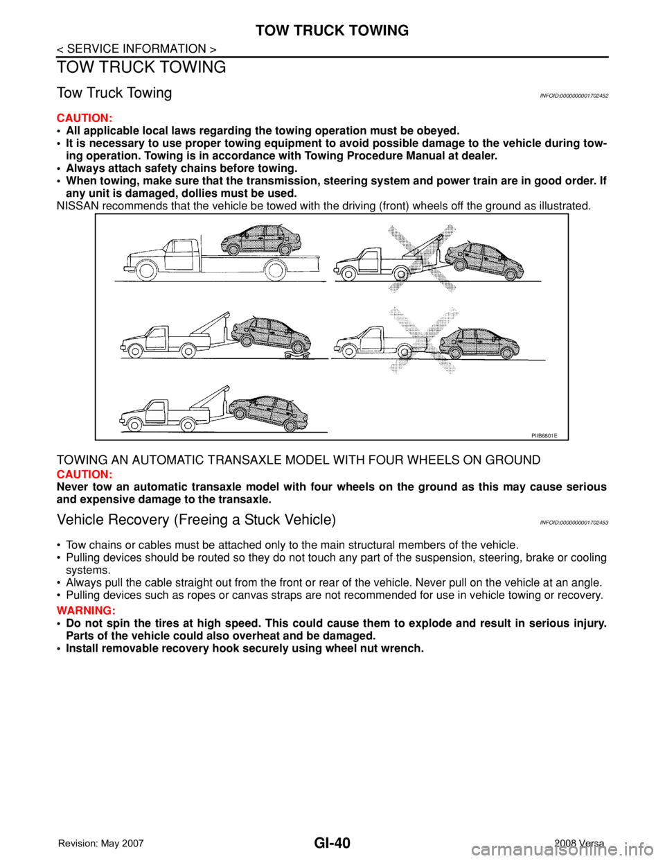
NISSAN recommends that the vehicle be towed with the driving (front) wheels off the ground as illustrated.
TOWING AN AUTOMATIC TRANSAXLE MODEL WITH FOUR WHEELS ON GROUND
CAUTION:
Never tow an automatic transaxle model with four wheels on the ground as this may cause serious
and expensive damage to the transaxle.
Vehicle Recovery (Freeing a Stuck Vehicle)INFOID:0000000001702453
• Tow chains or cables must be attached only to the main structural members of the vehicle.
• Pulling devices should be routed so they do not touch any part of the suspension, steering, brake or cooling
systems.
• Always pull the cable straight out from the front or rear of the vehicle. Never pull on the vehicle at an angle.
• Pulling devices such as ropes or canvas straps are not recommended for use in vehicle towing or recovery.
WARNING:
• Do not spin the tires at high speed. This could cause them to explode and result in serious injury.
Parts of the vehicle could also overheat and be damaged.
• Install removable recovery hook securely using wheel nut wrench.
PIIB6801E
Page 1907 of 2771
GW-6
< SERVICE INFORMATION >
SQUEAK AND RATTLE TROUBLE DIAGNOSES
If the noise can be duplicated easily during the test drive, to help identify the source of the noise, try to dupli-
cate the noise with the vehicle stopped by doing one or all of the following:
1) Close a door.
2) Tap or push/pull around the area where the noise appears to be coming from.
3) Rev the engine.
4) Use a floor jack to recreate vehicle “twist”.
5) At idle, apply engine load (electrical load, half-clutch on M/T model, drive position on A/T model).
6) Raise the vehicle on a hoist and hit a tire with a rubber hammer.
• Drive the vehicle and attempt to duplicate the conditions the customer states exist when the noise occurs.
• If it is difficult to duplicate the noise, drive the vehicle slowly on an undulating or rough road to stress the
vehicle body.
CHECK RELATED SERVICE BULLETINS
After verifying the customer concern or symptom, check ASIST for Technical Service Bulletins (TSBs) related
to that concern or symptom.
If a TSB relates to the symptom, follow the procedure to repair the noise.
LOCATE THE NOISE AND IDENTIFY THE ROOT CAUSE
1. Narrow down the noise to a general area.To help pinpoint the source of the noise, use a listening tool
(Chassis Ear: J-39570, Engine Ear: J-39565 and mechanic's stethoscope).
2. Narrow down the noise to a more specific area and identify the cause of the noise by:
• removing the components in the area that you suspect the noise is coming from.
Do not use too much force when removing clips and fasteners, otherwise clips and fasteners can be broken
or lost during the repair, resulting in the creation of new noise.
• tapping or pushing/pulling the component that you suspect is causing the noise.
Do not tap or push/pull the component with excessive force, otherwise the noise will be eliminated only tem-
porarily.
• feeling for a vibration with your hand by touching the component(s) that you suspect is (are) causing the
noise.
• placing a piece of paper between components that you suspect are causing the noise.
• looking for loose components and contact marks.
Refer to GW-7, "
Generic Squeak and Rattle Troubleshooting".
REPAIR THE CAUSE
• If the cause is a loose component, tighten the component securely.
• If the cause is insufficient clearance between components:
- separate components by repositioning or loosening and retightening the component, if possible.
- insulate components with a suitable insulator such as urethane pads, foam blocks, felt cloth tape or urethane
tape. A NISSAN Squeak and Rattle Kit (J-43980) is available through your authorized NISSAN Parts Depart-
ment.
CAUTION:
Do not use excessive force as many components are constructed of plastic and may be damaged.
Always check with the Parts Department for the latest parts information.
The following materials are contained in the NISSAN Squeak and Rattle Kit (J-43980). Each item can be
ordered separately as needed.
URETHANE PADS [1.5 mm (0.059 in) thick]
Insulates connectors, harness, etc.
76268-9E005: 100×135 mm (3.94×5.31 in)/76884-71L01: 60×85 mm (2.36×3.35 in)/76884-71L02: 15×25
mm (0.59×0.98 in)
INSULATOR (Foam blocks)
Insulates components from contact. Can be used to fill space behind a panel.
73982-9E000: 45 mm (1.77 in) thick, 50×50 mm (1.97×1.97 in)/73982-50Y00: 10 mm (0.39 in) thick,
50×50 mm (1.97×1.97 in)
INSULATOR (Light foam block)
80845-71L00: 30 mm (1.18 in) thick, 30×50 mm (1.18×1.97 in)
FELT CLOTH TAPE
Used to insulate where movement does not occur. Ideal for instrument panel applications.
68370-4B000: 15×25 mm (0.59×0.98 in) pad/68239-13E00: 5 mm (0.20 in) wide tape roll. The following
materials not found in the kit can also be used to repair squeaks and rattles.
UHMW (TEFLON) TAPE
Insulates where slight movement is present. Ideal for instrument panel applications.
Page 1909 of 2771

GW-8
< SERVICE INFORMATION >
SQUEAK AND RATTLE TROUBLE DIAGNOSES
Most of these incidents can be repaired by adjusting, securing or insulating the item(s) or component(s) caus-
ing the noise.
SUNROOF/HEADLINING
Noises in the sunroof/headlining area can often be traced to one of the following:
1. Sunroof lid, rail, linkage or seals making a rattle or light knocking noise
2. Sun visor shaft shaking in the holder
3. Front or rear windshield touching headliner and squeaking
Again, pressing on the components to stop the noise while duplicating the conditions can isolate most of these
incidents. Repairs usually consist of insulating with felt cloth tape.
OVERHEAD CONSOLE (FRONT AND REAR)
Overhead console noises are often caused by the console panel clips not being engaged correctly. Most of
these incidents are repaired by pushing up on the console at the clip locations until the clips engage.
In addition look for:
1. Loose harness or harness connectors.
2. Front console map/reading lamp lense loose.
3. Loose screws at console attachment points.
SEATS
When isolating seat noise it's important to note the position the seat is in and the load placed on the seat when
the noise is present. These conditions should be duplicated when verifying and isolating the cause of the
noise.
Cause of seat noise include:
1. Headrest rods and holder
2. A squeak between the seat pad cushion and frame
3. The rear seatback lock and bracket
These noises can be isolated by moving or pressing on the suspected components while duplicating the con-
ditions under which the noise occurs. Most of these incidents can be repaired by repositioning the component
or applying urethane tape to the contact area.
UNDERHOOD
Some interior noise may be caused by components under the hood or on the engine wall. The noise is then
transmitted into the passenger compartment.
Causes of transmitted underhood noise include:
1. Any component mounted to the engine wall
2. Components that pass through the engine wall
3. Engine wall mounts and connectors
4. Loose radiator mounting pins
5. Hood bumpers out of adjustment
6. Hood striker out of adjustment
These noises can be difficult to isolate since they cannot be reached from the interior of the vehicle. The best
method is to secure, move or insulate one component at a time and test drive the vehicle. Also, engine RPM
or load can be changed to isolate the noise. Repairs can usually be made by moving, adjusting, securing, or
insulating the component causing the noise.
Page 1913 of 2771
GW-12
< SERVICE INFORMATION >
WINDSHIELD GLASS
WARNING:
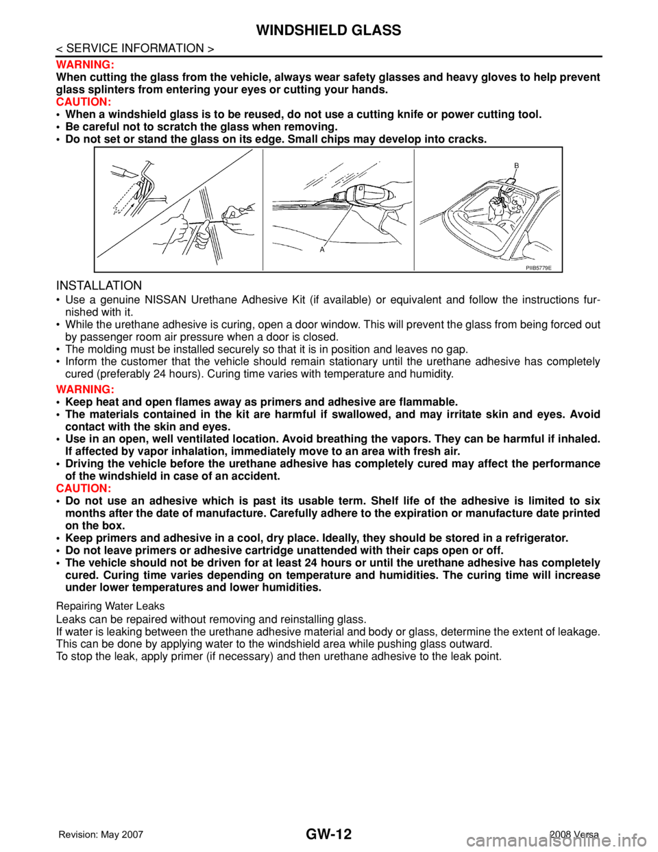
When cutting the glass from the vehicle, always wear safety glasses and heavy gloves to help prevent
glass splinters from entering your eyes or cutting your hands.
CAUTION:
• When a windshield glass is to be reused, do not use a cutting knife or power cutting tool.
• Be careful not to scratch the glass when removing.
• Do not set or stand the glass on its edge. Small chips may develop into cracks.
INSTALLATION
• Use a genuine NISSAN Urethane Adhesive Kit (if available) or equivalent and follow the instructions fur-
nished with it.
• While the urethane adhesive is curing, open a door window. This will prevent the glass from being forced out
by passenger room air pressure when a door is closed.
• The molding must be installed securely so that it is in position and leaves no gap.
• Inform the customer that the vehicle should remain stationary until the urethane adhesive has completely
cured (preferably 24 hours). Curing time varies with temperature and humidity.
WARNING:
• Keep heat and open flames away as primers and adhesive are flammable.
• The materials contained in the kit are harmful if swallowed, and may irritate skin and eyes. Avoid
contact with the skin and eyes.
• Use in an open, well ventilated location. Avoid breathing the vapors. They can be harmful if inhaled.
If affected by vapor inhalation, immediately move to an area with fresh air.
• Driving the vehicle before the urethane adhesive has completely cured may affect the performance
of the windshield in case of an accident.
CAUTION:
• Do not use an adhesive which is past its usable term. Shelf life of the adhesive is limited to six
months after the date of manufacture. Carefully adhere to the expiration or manufacture date printed
on the box.
• Keep primers and adhesive in a cool, dry place. Ideally, they should be stored in a refrigerator.
• Do not leave primers or adhesive cartridge unattended with their caps open or off.
• The vehicle should not be driven for at least 24 hours or until the urethane adhesive has completely
cured. Curing time varies depending on temperature and humidities. The curing time will increase
under lower temperatures and lower humidities.
Repairing Water Leaks
Leaks can be repaired without removing and reinstalling glass.
If water is leaking between the urethane adhesive material and body or glass, determine the extent of leakage.
This can be done by applying water to the windshield area while pushing glass outward.
To stop the leak, apply primer (if necessary) and then urethane adhesive to the leak point.
PIIB5779E
Page 1914 of 2771
OPERA WINDOW GLASS
GW-13
< SERVICE INFORMATION >
C
D
E
F
G
H
J
K
L
MA
B
GW
N
O
P
OPERA WINDOW GLASS
Removal and InstallationINFOID:0000000001704136
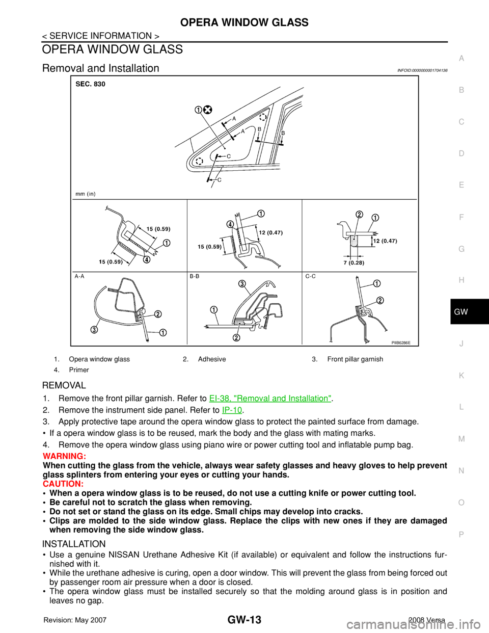
REMOVAL
1. Remove the front pillar garnish. Refer to EI-38, "Removal and Installation".
2. Remove the instrument side panel. Refer to IP-10
.
3. Apply protective tape around the opera window glass to protect the painted surface from damage.
• If a opera window glass is to be reused, mark the body and the glass with mating marks.
4. Remove the opera window glass using piano wire or power cutting tool and inflatable pump bag.
WARNING:
When cutting the glass from the vehicle, always wear safety glasses and heavy gloves to help prevent
glass splinters from entering your eyes or cutting your hands.
CAUTION:
• When a opera window glass is to be reused, do not use a cutting knife or power cutting tool.
• Be careful not to scratch the glass when removing.
• Do not set or stand the glass on its edge. Small chips may develop into cracks.
• Clips are molded to the side window glass. Replace the clips with new ones if they are damaged
when removing the side window glass.
INSTALLATION
• Use a genuine NISSAN Urethane Adhesive Kit (if available) or equivalent and follow the instructions fur-
nished with it.
• While the urethane adhesive is curing, open a door window. This will prevent the glass from being forced out
by passenger room air pressure when a door is closed.
• The opera window glass must be installed securely so that the molding around glass is in position and
leaves no gap.
PIIB6286E
1. Opera window glass 2. Adhesive 3. Front pillar garnish
4. Primer