2008 NISSAN LATIO ECU
[x] Cancel search: ECUPage 2360 of 2771
MTC-22
< SERVICE INFORMATION >
TROUBLE DIAGNOSIS
TROUBLE DIAGNOSIS
CONSULT-III Function (BCM)INFOID:0000000001704294
CONSULT-III can display each diagnostic item using the diagnostic test modes shown following.
DATA MONITOR
Display Item List
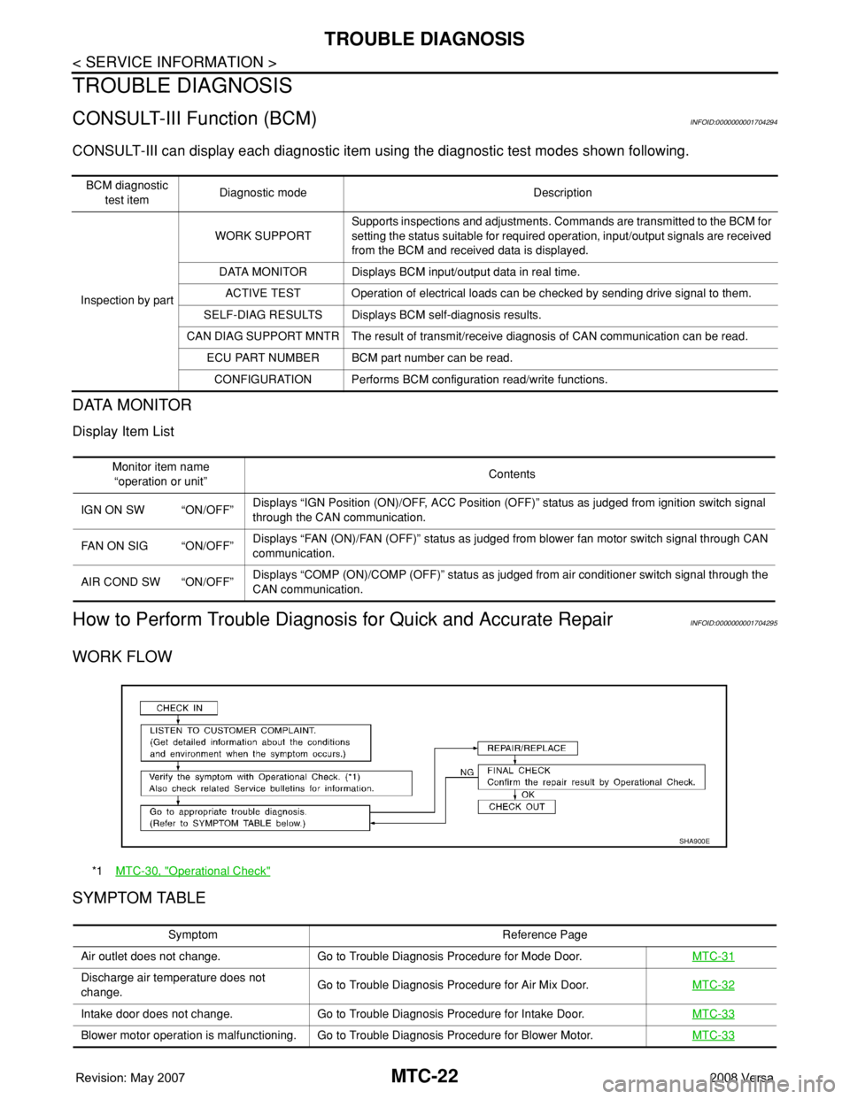
How to Perform Trouble Diagnosis for Quick and Accurate RepairINFOID:0000000001704295
WORK FLOW
SYMPTOM TABLE
BCM diagnostic
test itemDiagnostic mode Description
Inspection by partWORK SUPPORTSupports inspections and adjustments. Commands are transmitted to the BCM for
setting the status suitable for required operation, input/output signals are received
from the BCM and received data is displayed.
DATA MONITOR Displays BCM input/output data in real time.
ACTIVE TEST Operation of electrical loads can be checked by sending drive signal to them.
SELF-DIAG RESULTS Displays BCM self-diagnosis results.
CAN DIAG SUPPORT MNTR The result of transmit/receive diagnosis of CAN communication can be read.
ECU PART NUMBER BCM part number can be read.
CONFIGURATION Performs BCM configuration read/write functions.
Monitor item name
“operation or unit”Contents
IGN ON SW “ON/OFF”Displays “IGN Position (ON)/OFF, ACC Position (OFF)” status as judged from ignition switch signal
through the CAN communication.
FAN ON SIG “ON/OFF”Displays “FAN (ON)/FAN (OFF)” status as judged from blower fan motor switch signal through CAN
communication.
AIR COND SW “ON/OFF”Displays “COMP (ON)/COMP (OFF)” status as judged from air conditioner switch signal through the
CAN communication.
*1MTC-30, "Operational Check"
SHA900E
Symptom Reference Page
Air outlet does not change. Go to Trouble Diagnosis Procedure for Mode Door.MTC-31
Discharge air temperature does not
change.Go to Trouble Diagnosis Procedure for Air Mix Door.MTC-32
Intake door does not change. Go to Trouble Diagnosis Procedure for Intake Door.MTC-33
Blower motor operation is malfunctioning. Go to Trouble Diagnosis Procedure for Blower Motor.MTC-33
Page 2394 of 2771
MTC-56
< SERVICE INFORMATION >
CONTROLLER
Disassembly and Assembly
INFOID:0000000001704310
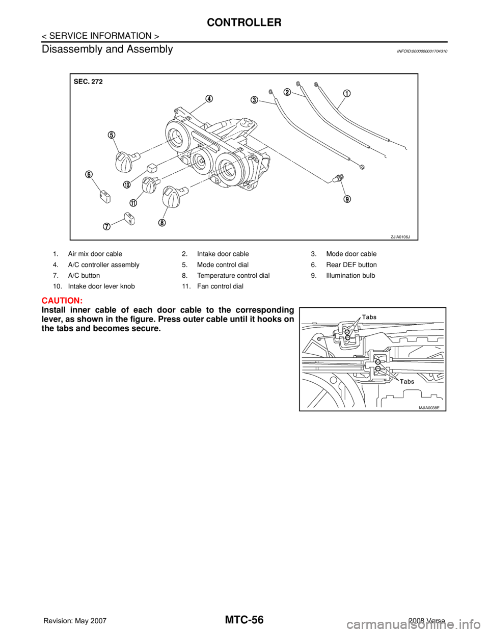
CAUTION:
Install inner cable of each door cable to the corresponding
lever, as shown in the figure. Press outer cable until it hooks on
the tabs and becomes secure.
1. Air mix door cable 2. Intake door cable 3. Mode door cable
4. A/C controller assembly 5. Mode control dial 6. Rear DEF button
7. A/C button 8. Temperature control dial 9. Illumination bulb
10. Intake door lever knob 11. Fan control dial
ZJIA0106J
MJIA0038E
Page 2400 of 2771
MTC-62
< SERVICE INFORMATION >
BLOWER MOTOR
BLOWER MOTOR
Removal and InstallationINFOID:0000000001704314
REMOVAL
1. Remove instrument panel and pad. Refer to IP-10.
2. Remove side ventilator duct (right). Refer to MTC-69, "
Removal and Installation".
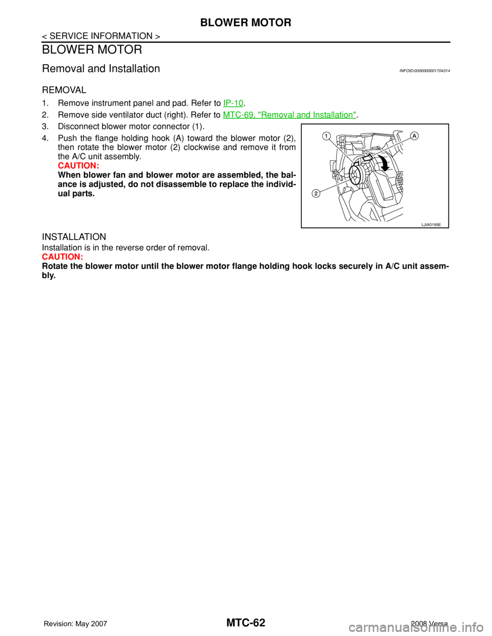
3. Disconnect blower motor connector (1).
4. Push the flange holding hook (A) toward the blower motor (2),
then rotate the blower motor (2) clockwise and remove it from
the A/C unit assembly.
CAUTION:
When blower fan and blower motor are assembled, the bal-
ance is adjusted, do not disassemble to replace the individ-
ual parts.
INSTALLATION
Installation is in the reverse order of removal.
CAUTION:
Rotate the blower motor until the blower motor flange holding hook locks securely in A/C unit assem-
bly.
LJIA0199E
Page 2406 of 2771
MTC-68
< SERVICE INFORMATION >
AIR CONDITIONER FILTER
AIR CONDITIONER FILTER
Removal and InstallationINFOID:0000000001704320
FUNCTION
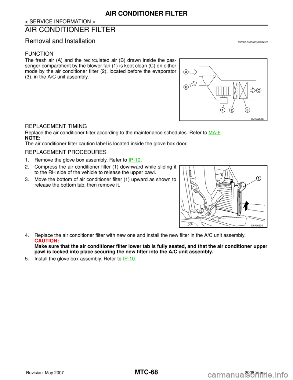
The fresh air (A) and the recirculated air (B) drawn inside the pas-
senger compartment by the blower fan (1) is kept clean (C) on either
mode by the air conditioner filter (2), located before the evaporator
(3), in the A/C unit assembly.
REPLACEMENT TIMING
Replace the air conditioner filter according to the maintenance schedules. Refer to MA-6.
NOTE:
The air conditioner filter caution label is located inside the glove box door.
REPLACEMENT PROCEDURES
1. Remove the glove box assembly. Refer to IP-10.
2. Compress the air conditioner filter (1) downward while sliding it
to the RH side of the vehicle to release the upper pawl.
3. Move the bottom of air conditioner filter (1) upward as shown to
release the bottom tab, then remove it.
4. Replace the air conditioner filter with new one and install the new filter in the A/C unit assembly.
CAUTION:
Make sure that the air conditioner filter lower tab is fully seated, and that the air conditioner upper
pawl is locked into place securing the new filter into the A/C unit assembly.
5. Install the glove box assembly. Refer to IP-10
.
WJIA2253E
SJIA0652E
Page 2421 of 2771
REFRIGERANT LINES
MTC-83
< SERVICE INFORMATION >
C
D
E
F
G
H
I
K
L
MA
B
MTC
N
O
P
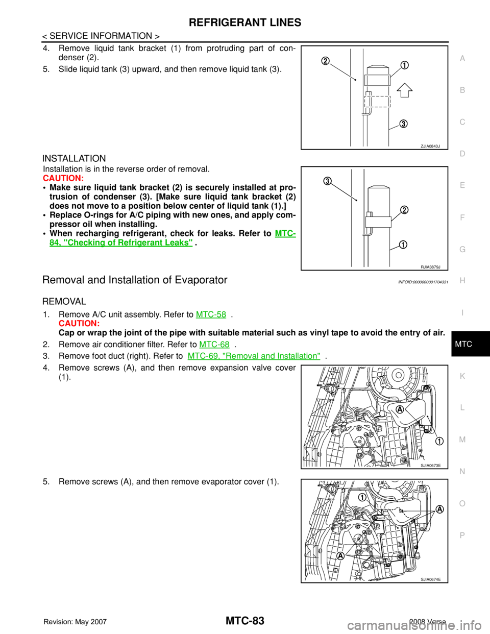
4. Remove liquid tank bracket (1) from protruding part of con-
denser (2).
5. Slide liquid tank (3) upward, and then remove liquid tank (3).
INSTALLATION
Installation is in the reverse order of removal.
CAUTION:
• Make sure liquid tank bracket (2) is securely installed at pro-
trusion of condenser (3). [Make sure liquid tank bracket (2)
does not move to a position below center of liquid tank (1).]
• Replace O-rings for A/C piping with new ones, and apply com-
pressor oil when installing.
• When recharging refrigerant, check for leaks. Refer to MTC-
84, "Checking of Refrigerant Leaks" .
Removal and Installation of EvaporatorINFOID:0000000001704331
REMOVAL
1. Remove A/C unit assembly. Refer to MTC-58 .
CAUTION:
Cap or wrap the joint of the pipe with suitable material such as vinyl tape to avoid the entry of air.
2. Remove air conditioner filter. Refer to MTC-68
.
3. Remove foot duct (right). Refer to MTC-69, "
Removal and Installation" .
4. Remove screws (A), and then remove expansion valve cover
(1).
5. Remove screws (A), and then remove evaporator cover (1).
ZJIA0843J
RJIA3879J
SJIA0673E
SJIA0674E
Page 2425 of 2771
REFRIGERANT LINES
MTC-87
< SERVICE INFORMATION >
C
D
E
F
G
H
I
K
L
MA
B
MTC
N
O
P
Check all around the service valves. Ensure service valve caps are secured on the service valves (to
prevent leaks).
NOTE:
After removing A/C manifold gauge set from service valves, wipe any residue from valves to prevent any
false readings by leak detector.
• Cooling unit (Evaporator)
With engine OFF, turn blower fan on “High” for at least 15 seconds to dissipate any refrigerant trace in
the cooling unit. Wait a minimum of 10 minutes accumulation time (refer to the manufacturer’s recom-
mended procedure for actual wait time) before inserting the leak detector probe into the drain hose.
Keep the probe inserted for at least 10 seconds. Use caution not to contaminate the probe tip with water
or dirt that may be in the drain hose.
5. If a leak detector detects a leak, verify at least once by blowing compressed air into area of suspected
leak, then repeat check as outlined above.
6. Do not stop when one leak is found. Continue to check for additional leaks at all system components.
If no leaks are found, perform steps 7-10.
7. Start engine.
8. Set the heater A/C control as follows;
a. A/C switch: ON
b. Mode control dial position: VENT (Ventilation)
c. Intake door lever position: Recirculation
d. Max. cold temperature
e. Fan speed: High
9. Run engine at 1,500 rpm for at least 2 minutes.
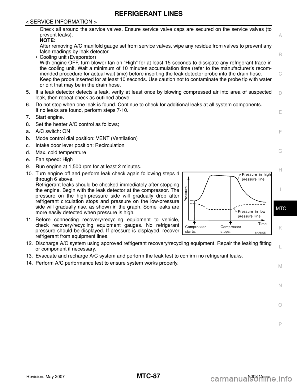
10. Turn engine off and perform leak check again following steps 4
through 6 above.
Refrigerant leaks should be checked immediately after stopping
the engine. Begin with the leak detector at the compressor. The
pressure on the high-pressure side will gradually drop after
refrigerant circulation stops and pressure on the low-pressure
side will gradually rise, as shown in the graph. Some leaks are
more easily detected when pressure is high.
11. Before connecting recovery/recycling equipment to vehicle,
check recovery/recycling equipment gauges. No refrigerant
pressure should be displayed. If pressure is displayed, recover
refrigerant from equipment lines.
12. Discharge A/C system using approved refrigerant recovery/recycling equipment. Repair the leaking fitting
or component if necessary.
13. Evacuate and recharge A/C system and perform the leak test to confirm no refrigerant leaks.
14. Perform A/C performance test to ensure system works properly.
SHA839E
Page 2430 of 2771
PB-4
< SERVICE INFORMATION >
PARKING BRAKE CONTROL
PARKING BRAKE CONTROL
On-Vehicle ServiceINFOID:0000000001703814
INSPECTION
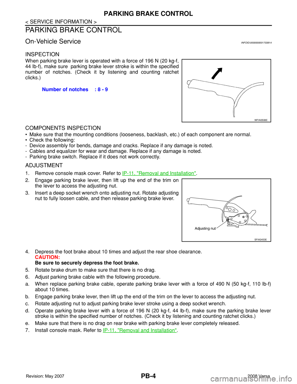
When parking brake lever is operated with a force of 196 N (20 kg-f,
44 lb-f), make sure parking brake lever stroke is within the specified
number of notches. (Check it by listening and counting ratchet
clicks.)
COMPONENTS INSPECTION
• Make sure that the mounting conditions (looseness, backlash, etc.) of each component are normal.
• Check the following:
- Device assembly for bends, damage and cracks. Replace if any damage is noted.
- Cables and equalizer for wear and damage. Replace if any damage is noted.
- Parking brake switch. Replace if it does not work correctly.
ADJUSTMENT
1. Remove console mask cover. Refer to IP-11, "Removal and Installation".
2. Engage parking brake lever, then lift up the end of the trim on
the lever to access the adjusting nut.
3. Insert a deep socket wrench onto adjusting nut. Rotate adjusting
nut to fully loosen cable, and then release parking brake lever.
4. Depress the foot brake about 10 times and adjust the rear shoe clearance.
CAUTION:
Be sure to securely depress the foot brake.
5. Rotate brake drum to make sure that there is no drag.
6. Adjust parking brake cable with the following procedure.
a. When replace parking brake cable, operate parking brake lever with a force of 490 N (50 kg-f, 110 lb-f)
about 10 times.
b. Engage parking brake lever, then lift up the end of the trim on the lever to access the adjusting nut.
c. Rotate adjusting nut to adjust parking brake lever stroke using a deep socket wrench.
d. Operate parking brake lever with a force of 196 N (20 kg-f, 44 lb-f), make sure the parking brake lever
stroke is within the specified number of notches. (Check it by listening and counting ratchet clicks.)
e. Make sure that there is no drag on rear brake with parking brake lever completely released.
7. Install console mask. Refer to IP-11, "
Removal and Installation". Number of notches : 8 - 9
WFIA0508E
SFIA2453E
Page 2493 of 2771

PG-60
< SERVICE INFORMATION >
HARNESS
SEN/PW EC Sensor Power Supply
SESCVT CVT Secondary Pressure Sensor Solenoid Valve
SHIFT AT A/T Shift Lock System
SHIFT CVT CVT Shift Lock System
SROOF RF Sunroof
SRS SRS Supplemental Restraint System
SSV/A AT Shift Solenoid Valve A
SSV/B AT Shift Solenoid Valve B
START SC Starting System
STM CVT Step Motor
STSIG CVT Start Signal Circuit
STOP/L LT Stop Lamp
TCV AT Torque Converter Clutch Solenoid Valve
TCV CVT Torque Converter Clutch Solenoid Valve
T/LID BL Trunk Lid Opener
T/WARN WT Low Tire Pressure Warning System
TAIL/L LT Parking, License and Tail Lamps
TPS1 EC Throttle Position Sensor
TPS2 EC Throttle Position Sensor
TPS3 EC Throttle Position Sensor
TURN LT Turn Signal and Hazard Warning Lamps
VEHSEC BL Vehicle Security (Theft Warning) System
VENT/V EC EVAP Canister Vent Control Valve
VSSA/T AT Vehicle Speed Sensor A/T (Revolution Sensor)
VSSMTR AT Vehicle Speed Sensor MTR
WARN DI Warning Lamps
WINDOW GW Power Window
WIP/R WW Rear Wiper and Washer
WIPER WW Front Wiper and Washer