2008 NISSAN LATIO ECU
[x] Cancel search: ECUPage 2513 of 2771
STEERING WHEEL
PS-7
< SERVICE INFORMATION >
C
D
E
F
H
I
J
K
L
MA
B
PS
N
O
P
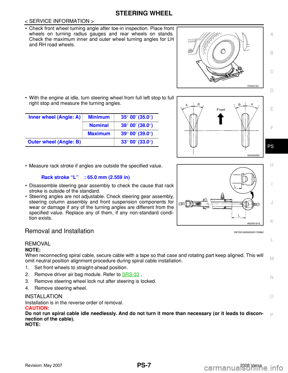
• Check front wheel turning angle after toe-in inspection. Place front
wheels on turning radius gauges and rear wheels on stands.
Check the maximum inner and outer wheel turning angles for LH
and RH road wheels.
• With the engine at idle, turn steering wheel from full left stop to full
right stop and measure the turning angles.
• Measure rack stroke if angles are outside the specified value.
• Disassemble steering gear assembly to check the cause that rack
stroke is outside of the standard.
• Steering angles are not adjustable. Check steering gear assembly,
steering column assembly and front suspension components for
wear or damage if any of the turning angles are different from the
specified value. Replace any of them, if any non-standard condi-
tion exists.
Removal and InstallationINFOID:0000000001703860
REMOVAL
NOTE:
When reconnecting spiral cable, secure cable with a tape so that case and rotating part keep aligned. This will
omit neutral position alignment procedure during spiral cable installation.
1. Set front wheels to straight-ahead position.
2. Remove driver air bag module. Refer to SRS-33
.
3. Remove steering wheel lock nut after steering is locked.
4. Remove steering wheel.
INSTALLATION
Installation is in the reverse order of removal.
CAUTION:
Do not run spiral cable idle needlessly. And do not turn it more than necessary (or it leads to discon-
nection of the cable).
NOTE:
FAA0016D
Inner wheel (Angle: A) Minimum 35° 00′ (35.0°)
Nominal 38° 00′ (38.0°)
Maximum 39° 00′ (39.0°)
Outer wheel (Angle: B) 33° 00′ (33.0°)
SGIA0055E
Rack stroke “L” : 65.0 mm (2.559 in)
WGIA0181E
Page 2516 of 2771
PS-10
< SERVICE INFORMATION >
STEERING COLUMN
8. Remove bolt of intermediate shaft (upper side), and then remove intermediate shaft from steering column
assembly.
9. Remove steering column assembly mounting nuts, and then remove steering column assembly from vehi-
cle.
10. Remove bolt of intermediate shaft (lower side), and then remove intermediate shaft from vehicle.
11. Remove screws of bracket and EPS control unit, and then remove bracket and EPS control unit from
steering column assembly.
INSPECTION AFTER REMOVAL
• Check each part of steering column assembly, EPS control unit and intermediate shaft for damage and .
replace as necessary.
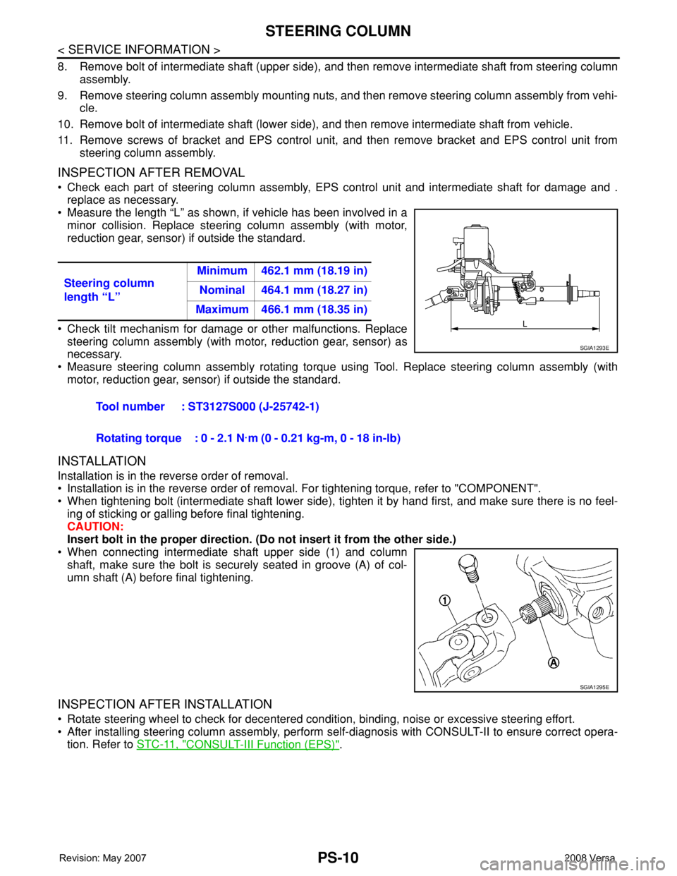
• Measure the length “L” as shown, if vehicle has been involved in a
minor collision. Replace steering column assembly (with motor,
reduction gear, sensor) if outside the standard.
• Check tilt mechanism for damage or other malfunctions. Replace
steering column assembly (with motor, reduction gear, sensor) as
necessary.
• Measure steering column assembly rotating torque using Tool. Replace steering column assembly (with
motor, reduction gear, sensor) if outside the standard.
INSTALLATION
Installation is in the reverse order of removal.
• Installation is in the reverse order of removal. For tightening torque, refer to "COMPONENT".
• When tightening bolt (intermediate shaft lower side), tighten it by hand first, and make sure there is no feel-
ing of sticking or galling before final tightening.
CAUTION:
Insert bolt in the proper direction. (Do not insert it from the other side.)
• When connecting intermediate shaft upper side (1) and column
shaft, make sure the bolt is securely seated in groove (A) of col-
umn shaft (A) before final tightening.
INSPECTION AFTER INSTALLATION
• Rotate steering wheel to check for decentered condition, binding, noise or excessive steering effort.
• After installing steering column assembly, perform self-diagnosis with CONSULT-II to ensure correct opera-
tion. Refer to STC-11, "
CONSULT-III Function (EPS)". Steering column
length “L”Minimum 462.1 mm (18.19 in)
Nominal 464.1 mm (18.27 in)
Maximum 466.1 mm (18.35 in)
Tool number : ST3127S000 (J-25742-1)
Rotating torque : 0 - 2.1 N·m (0 - 0.21 kg-m, 0 - 18 in-lb)
SGIA1293E
SGIA1295E
Page 2518 of 2771
PS-12
< SERVICE INFORMATION >
POWER STEERING GEAR
POWER STEERING GEAR
Removal and InstallationINFOID:0000000001703862
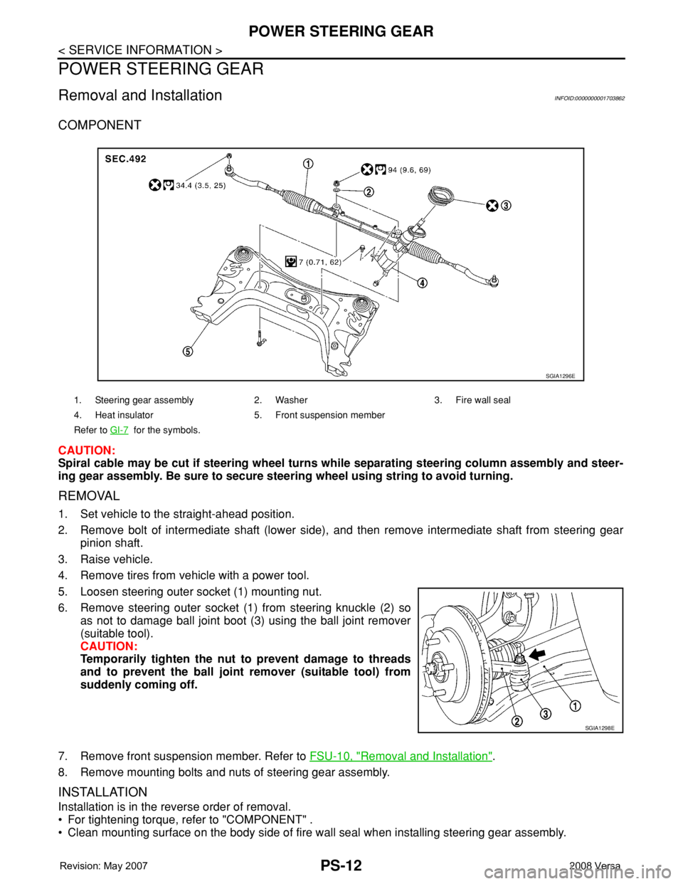
COMPONENT
CAUTION:
Spiral cable may be cut if steering wheel turns while separating steering column assembly and steer-
ing gear assembly. Be sure to secure steering wheel using string to avoid turning.
REMOVAL
1. Set vehicle to the straight-ahead position.
2. Remove bolt of intermediate shaft (lower side), and then remove intermediate shaft from steering gear
pinion shaft.
3. Raise vehicle.
4. Remove tires from vehicle with a power tool.
5. Loosen steering outer socket (1) mounting nut.
6. Remove steering outer socket (1) from steering knuckle (2) so
as not to damage ball joint boot (3) using the ball joint remover
(suitable tool).
CAUTION:
Temporarily tighten the nut to prevent damage to threads
and to prevent the ball joint remover (suitable tool) from
suddenly coming off.
7. Remove front suspension member. Refer to FSU-10, "
Removal and Installation".
8. Remove mounting bolts and nuts of steering gear assembly.
INSTALLATION
Installation is in the reverse order of removal.
• For tightening torque, refer to "COMPONENT" .
• Clean mounting surface on the body side of fire wall seal when installing steering gear assembly.
1. Steering gear assembly 2. Washer 3. Fire wall seal
4. Heat insulator 5. Front suspension member
Refer to GI-7
for the symbols.
SGIA1296E
SGIA1298E
Page 2521 of 2771
POWER STEERING GEAR
PS-15
< SERVICE INFORMATION >
C
D
E
F
H
I
J
K
L
MA
B
PS
N
O
P
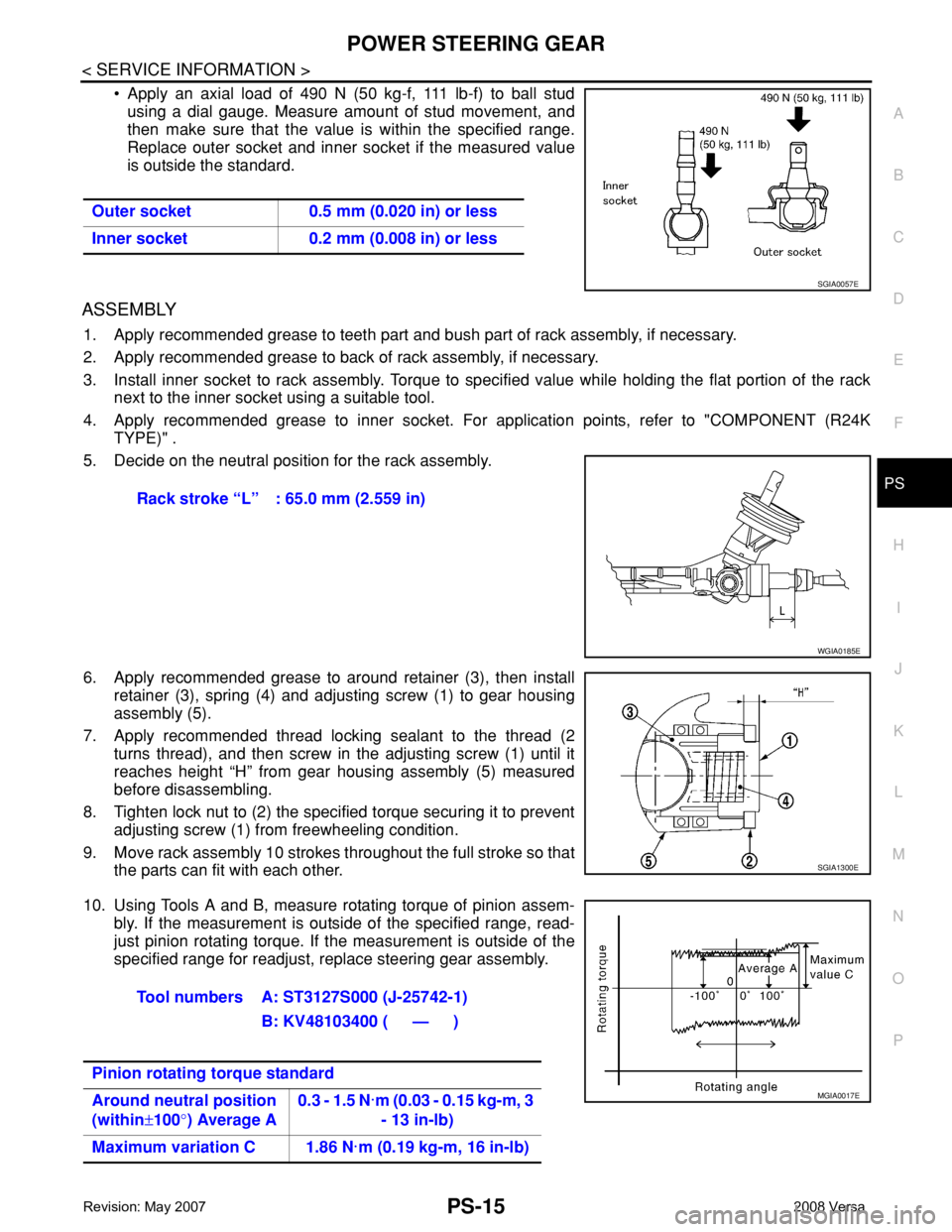
• Apply an axial load of 490 N (50 kg-f, 111 lb-f) to ball stud
using a dial gauge. Measure amount of stud movement, and
then make sure that the value is within the specified range.
Replace outer socket and inner socket if the measured value
is outside the standard.
ASSEMBLY
1. Apply recommended grease to teeth part and bush part of rack assembly, if necessary.
2. Apply recommended grease to back of rack assembly, if necessary.
3. Install inner socket to rack assembly. Torque to specified value while holding the flat portion of the rack
next to the inner socket using a suitable tool.
4. Apply recommended grease to inner socket. For application points, refer to "COMPONENT (R24K
TYPE)" .
5. Decide on the neutral position for the rack assembly.
6. Apply recommended grease to around retainer (3), then install
retainer (3), spring (4) and adjusting screw (1) to gear housing
assembly (5).
7. Apply recommended thread locking sealant to the thread (2
turns thread), and then screw in the adjusting screw (1) until it
reaches height “H” from gear housing assembly (5) measured
before disassembling.
8. Tighten lock nut to (2) the specified torque securing it to prevent
adjusting screw (1) from freewheeling condition.
9. Move rack assembly 10 strokes throughout the full stroke so that
the parts can fit with each other.
10. Using Tools A and B, measure rotating torque of pinion assem-
bly. If the measurement is outside of the specified range, read-
just pinion rotating torque. If the measurement is outside of the
specified range for readjust, replace steering gear assembly. Outer socket 0.5 mm (0.020 in) or less
Inner socket 0.2 mm (0.008 in) or less
SGIA0057E
Rack stroke “L” : 65.0 mm (2.559 in)
WGIA0185E
SGIA1300E
Tool numbers A: ST3127S000 (J-25742-1)
B: KV48103400 ( — )
Pinion rotating torque standard
Around neutral position
(within±100°) Average A0.3 - 1.5 N·m (0.03 - 0.15 kg-m, 3
- 13 in-lb)
Maximum variation C 1.86 N·m (0.19 kg-m, 16 in-lb)
MGIA0017E
Page 2522 of 2771
PS-16
< SERVICE INFORMATION >
POWER STEERING GEAR
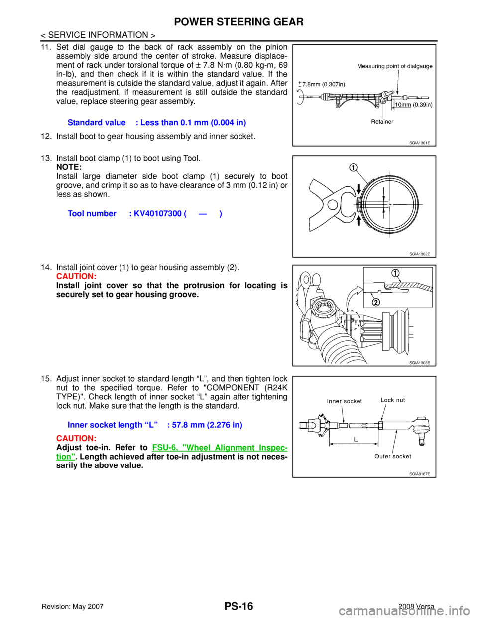
11. Set dial gauge to the back of rack assembly on the pinion
assembly side around the center of stroke. Measure displace-
ment of rack under torsional torque of ± 7.8 N·m (0.80 kg-m, 69
in-lb), and then check if it is within the standard value. If the
measurement is outside the standard value, adjust it again. After
the readjustment, if measurement is still outside the standard
value, replace steering gear assembly.
12. Install boot to gear housing assembly and inner socket.
13. Install boot clamp (1) to boot using Tool.
NOTE:
Install large diameter side boot clamp (1) securely to boot
groove, and crimp it so as to have clearance of 3 mm (0.12 in) or
less as shown.
14. Install joint cover (1) to gear housing assembly (2).
CAUTION:
Install joint cover so that the protrusion for locating is
securely set to gear housing groove.
15. Adjust inner socket to standard length “L”, and then tighten lock
nut to the specified torque. Refer to "COMPONENT (R24K
TYPE)". Check length of inner socket “L” again after tightening
lock nut. Make sure that the length is the standard.
CAUTION:
Adjust toe-in. Refer to FSU-6, "
Wheel Alignment Inspec-
tion". Length achieved after toe-in adjustment is not neces-
sarily the above value.Standard value : Less than 0.1 mm (0.004 in)
SGIA1301E
Tool number : KV40107300 ( — )
SGIA1302E
SGIA1303E
Inner socket length “L” : 57.8 mm (2.276 in)
SGIA0167E
Page 2535 of 2771
SQUEAK AND RATTLE TROUBLE DIAGNOSES
RF-5
< SYMPTOM DIAGNOSIS >
C
D
E
F
G
H
J
K
L
MA
B
RF
N
O
P
If possible, drive the vehicle with the customer until the noise is duplicated. Note any additional information on
the Diagnostic Worksheet regarding the conditions or location of the noise. This information can be used to
duplicate the same conditions when you confirm the repair.
If the noise can be duplicated easily during the test drive, to help identify the source of the noise, try to dupli-
cate the noise with the vehicle stopped by doing one or all of the following:
1) Close a door.
2) Tap or push/pull around the area where the noise appears to be coming from.
3) Rev the engine.
4) Use a floor jack to recreate vehicle “twist”.
5) At idle, apply engine load (electrical load, half-clutch on M/T model, drive position on A/T model).
6) Raise the vehicle on a hoist and hit a tire with a rubber hammer.
• Drive the vehicle and attempt to duplicate the conditions the customer states exist when the noise occurs.
• If it is difficult to duplicate the noise, drive the vehicle slowly on an undulating or rough road to stress the
vehicle body.
CHECK RELATED SERVICE BULLETINS
After verifying the customer concern or symptom, check ASIST for Technical Service Bulletins (TSBs) related
to that concern or symptom.
If a TSB relates to the symptom, follow the procedure to repair the noise.
LOCATE THE NOISE AND IDENTIFY THE ROOT CAUSE
1. Narrow down the noise to a general area. To help pinpoint the source of the noise, use a listening tool
(Engine Ear or mechanics stethoscope).
2. Narrow down the noise to a more specific area and identify the cause of the noise by:
• removing the components in the area that you suspect the noise is coming from.
Do not use too much force when removing clips and fasteners, otherwise clips and fastener can be broken
or lost during the repair, resulting in the creation of new noise.
• tapping or pushing/pulling the component that you suspect is causing the noise.
Do not tap or push/pull the component with excessive force, otherwise the noise will be eliminated only tem-
porarily.
• feeling for a vibration with your hand by touching the component(s) that you suspect is (are) causing the
noise.
• placing a piece of paper between components that you suspect are causing the noise.
• looking for loose components and contact marks.
Refer to RF-6, "
Generic Squeak and Rattle Troubleshooting".
REPAIR THE CAUSE
• If the cause is a loose component, tighten the component securely.
• If the cause is insufficient clearance between components:
- separate components by repositioning or loosening and retightening the component, if possible.
- insulate components with a suitable insulator such as urethane pads, foam blocks, felt cloth tape or urethane
tape are available through your authorized Nissan Parts Department.
CAUTION:
Do not use excessive force as many components are constructed of plastic and may be damaged.
NOTE:
Always check with the Parts Department for the latest parts information.
Each item can be ordered separately as needed.
URETHANE PADS [1.5 mm (0.059 in) thick]
Insulates connectors, harness, etc.
76268-9E005: 100 × 135 mm (3.94 × 5.31 in)/76884-71L01: 60 × 85 mm (2.36 × 3.35 in)/76884-71L02: 15 ×
25 mm (0.59 × 0.98 in)
INSULATOR (Foam blocks)
Insulates components from contact. Can be used to fill space behind a panel.
73982-9E000: 45 mm (1.77 in) thick, 50 × 50 mm (1.97 × 1.97 in)/73982-50Y00: 10 mm (0.39 in) thick, 50
× 50 mm (1.97 × 1.97 in)
INSULATOR (Light foam block)
80845-71L00: 30 mm (1.18 in) thick, 30 × 50 mm (1.18 × 1.97 in)
FELT CLOTH TAPE
Used to insulate where movement does not occur. Ideal for instrument panel applications.
68370-4B000: 15 × 25 mm (0.59 × 0.98 in) pad/68239-13E00: 5 mm (0.20 in) wide tape roll
Page 2537 of 2771

SQUEAK AND RATTLE TROUBLE DIAGNOSES
RF-7
< SYMPTOM DIAGNOSIS >
C
D
E
F
G
H
J
K
L
MA
B
RF
N
O
P
2. Trunk lid striker out of adjustment
3. The trunk lid torsion bars knocking together
4. A loose license plate or bracket
Most of these incidents can be repaired by adjusting, securing or insulating the item(s) or component(s) caus-
ing the noise.
SUNROOF/HEADLINING
Noises in the sunroof/headlining area can often be traced to one of the following:
1. Sunroof lid, rail, linkage or seals making a rattle or light knocking noise
2. Sun visor shaft shaking in the holder
3. Front or rear windshield touching headliner and squeaking
Again, pressing on the components to stop the noise while duplicating the conditions can isolate most of these
incidents. Repairs usually consist of insulating with felt cloth tape.
OVERHEAD CONSOLE (FRONT AND REAR)
Overhead console noises are often caused by the console panel clips not being engaged correctly. Most of
these incidents are repaired by pushing up on the console at the clip locations until the clips engage.
In addition look for:
1. Loose harness or harness connectors.
2. Front console map/reading lamp lens loose.
3. Loose screws at console attachment points.
SEATS
When isolating seat noise it's important to note the position the seat is in and the load placed on the seat when
the noise is present. These conditions should be duplicated when verifying and isolating the cause of the
noise.
Cause of seat noise include:
1. Headrest rods and holder
2. A squeak between the seat pad cushion and frame
3. The rear seatback lock and bracket
These noises can be isolated by moving or pressing on the suspected components while duplicating the con-
ditions under which the noise occurs. Most of these incidents can be repaired by repositioning the component
or applying urethane tape to the contact area.
UNDERHOOD
Some interior noise may be caused by components under the hood or on the engine wall. The noise is then
transmitted into the passenger compartment.
Causes of transmitted underhood noise include:
1. Any component installed on the engine wall
2. Components that pass through the engine wall
3. Engine wall mounts and connectors
4. Loose radiator pins
5. Hood bumpers out of adjustment
6. Hood striker out of adjustment
These noises can be difficult to isolate since they cannot be reached from the interior of the vehicle. The best
method is to secure, move or insulate one component at a time and test drive the vehicle. Also, engine RPM
or load can be changed to isolate the noise. Repairs can usually be made by moving, adjusting, securing, or
insulating the component causing the noise.
Page 2545 of 2771
TROUBLE DIAGNOSIS
RF-15
< FUNCTION DIAGNOSIS >
C
D
E
F
G
H
J
K
L
MA
B
RF
N
O
P
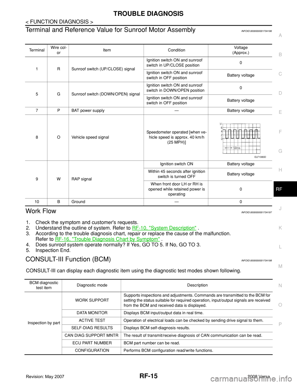
Terminal and Reference Value for Sunroof Motor AssemblyINFOID:0000000001704196
Work FlowINFOID:0000000001704197
1. Check the symptom and customer's requests.
2. Understand the outline of system. Refer to RF-10, "
System Description" .
3. According to the trouble diagnosis chart, repair or replace the cause of the malfunction.
Refer to RF-16, "
Trouble Diagnosis Chart by Symptom" .
4. Does sunroof system operate normally? If Yes, GO TO 5. If No, GO TO 3.
5. Inspection End.
CONSULT-III Function (BCM)INFOID:0000000001704198
CONSULT-III can display each diagnostic item using the diagnostic test modes shown following.
Te r m i n a lWire col-
orItem ConditionVoltag e
(Approx.)
1 R Sunroof switch (UP/CLOSE) signalIgnition switch ON and sunroof
switch in UP/CLOSE position0
Ignition switch ON and sunroof
switch in OFF positionBattery voltage
5 G Sunroof switch (DOWN/OPEN) signalIgnition switch ON and sunroof
switch in DOWN/OPEN position0
Ignition switch ON and sunroof
switch in OFF positionBattery voltage
7PBAT power supply — Battery voltage
8 O Vehicle speed signalSpeedometer operated [when ve-
hicle speed is approx. 40 km/h
(25 MPH)]
9 W RAP signalIgnition switch ON Battery voltage
Within 45 seconds after ignition
switch is turned OFFBattery voltage
When front door LH or RH is
opened while retained power is
operating0
10 B Ground — 0
ELF1080D
BCM diagnostic
test itemDiagnostic mode Description
Inspection by partWORK SUPPORTSupports inspections and adjustments. Commands are transmitted to the BCM for
setting the status suitable for required operation, input/output signals are received
from the BCM and received data is displayed.
DATA MONITOR Displays BCM input/output data in real time.
ACTIVE TEST Operation of electrical loads can be checked by sending drive signal to them.
SELF-DIAG RESULTS Displays BCM self-diagnosis results.
CAN DIAG SUPPORT MNTR The result of transmit/receive diagnosis of CAN communication can be read.
ECU PART NUMBER BCM part number can be read.
CONFIGURATION Performs BCM configuration read/write functions.