Page 2359 of 2771
AIR CONDITIONER CONTROL
MTC-21
< SERVICE INFORMATION >
C
D
E
F
G
H
I
K
L
MA
B
MTC
N
O
P
CAN Communication System DescriptionINFOID:0000000001704293
Refer to LAN-6.
WJIA2234E
Page 2360 of 2771

MTC-22
< SERVICE INFORMATION >
TROUBLE DIAGNOSIS
TROUBLE DIAGNOSIS
CONSULT-III Function (BCM)INFOID:0000000001704294
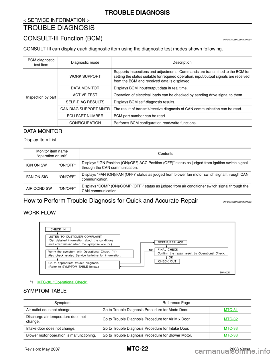
CONSULT-III can display each diagnostic item using the diagnostic test modes shown following.
DATA MONITOR
Display Item List
How to Perform Trouble Diagnosis for Quick and Accurate RepairINFOID:0000000001704295
WORK FLOW
SYMPTOM TABLE
BCM diagnostic
test itemDiagnostic mode Description
Inspection by partWORK SUPPORTSupports inspections and adjustments. Commands are transmitted to the BCM for
setting the status suitable for required operation, input/output signals are received
from the BCM and received data is displayed.
DATA MONITOR Displays BCM input/output data in real time.
ACTIVE TEST Operation of electrical loads can be checked by sending drive signal to them.
SELF-DIAG RESULTS Displays BCM self-diagnosis results.
CAN DIAG SUPPORT MNTR The result of transmit/receive diagnosis of CAN communication can be read.
ECU PART NUMBER BCM part number can be read.
CONFIGURATION Performs BCM configuration read/write functions.
Monitor item name
“operation or unit”Contents
IGN ON SW “ON/OFF”Displays “IGN Position (ON)/OFF, ACC Position (OFF)” status as judged from ignition switch signal
through the CAN communication.
FAN ON SIG “ON/OFF”Displays “FAN (ON)/FAN (OFF)” status as judged from blower fan motor switch signal through CAN
communication.
AIR COND SW “ON/OFF”Displays “COMP (ON)/COMP (OFF)” status as judged from air conditioner switch signal through the
CAN communication.
*1MTC-30, "Operational Check"
SHA900E
Symptom Reference Page
Air outlet does not change. Go to Trouble Diagnosis Procedure for Mode Door.MTC-31
Discharge air temperature does not
change.Go to Trouble Diagnosis Procedure for Air Mix Door.MTC-32
Intake door does not change. Go to Trouble Diagnosis Procedure for Intake Door.MTC-33
Blower motor operation is malfunctioning. Go to Trouble Diagnosis Procedure for Blower Motor.MTC-33
Page 2361 of 2771
TROUBLE DIAGNOSIS
MTC-23
< SERVICE INFORMATION >
C
D
E
F
G
H
I
K
L
MA
B
MTC
N
O
P
Component Parts and Harness Connector LocationINFOID:0000000001704296
ENGINE COMPARTMENT
PASSENGER COMPARTMENT
Magnet clutch does not engage in A/C, de-
frost/foot, or defrost mode.Go to Trouble Diagnosis Procedure for Magnet Clutch.MTC-37
Insufficient cooling Go to Trouble Diagnosis Procedure for Insufficient Cooling.MTC-45
Insufficient heating Go to Trouble Diagnosis Procedure for Insufficient Heating.MTC-52
Noise Go to Trouble Diagnosis Procedure for Noise.MTC-53
Symptom Reference Page
1. Refrigerant pressure sensor E17 2. A/C compressor F3
WJIA2235E
Page 2362 of 2771
MTC-24
< SERVICE INFORMATION >
TROUBLE DIAGNOSIS
1. Front air control M33 2. Front blower motor resistor M151 3. Thermo control amp. jumper connec-
tor (with CVT)
4. Thermo control amp. M42 (without CVT) 5. Front blower motor M62 6. Defrost A/C switch M41 (located on
back side of front air control)
WJIA2302E
Page 2363 of 2771
TROUBLE DIAGNOSIS
MTC-25
< SERVICE INFORMATION >
C
D
E
F
G
H
I
K
L
MA
B
MTC
N
O
P
SchematicINFOID:0000000001704297
WJWA0487E
Page 2364 of 2771
MTC-26
< SERVICE INFORMATION >
TROUBLE DIAGNOSIS
Wiring Diagram - Heater -
INFOID:0000000001704298
WITHOUT A/C
WJWA0485E
Page 2365 of 2771
TROUBLE DIAGNOSIS
MTC-27
< SERVICE INFORMATION >
C
D
E
F
G
H
I
K
L
MA
B
MTC
N
O
P
Wiring Diagram - A/C,M -INFOID:0000000001704299
WJWA0484E
Page 2366 of 2771
MTC-28
< SERVICE INFORMATION >
TROUBLE DIAGNOSIS
WJWA0486E