Page 200 of 2771
AT-188
< SERVICE INFORMATION >
TROUBLE DIAGNOSIS FOR SYMPTOMS
2. Check the following items:
- Shift valve B
- Shift solenoid valve B
- Pilot valve
- Pilot filter
OK or NG
OK >> GO TO 8.
NG >> Repair or replace damaged parts.
8.CHECK SYMPTOM
Check again. Refer to AT-55, "
Cruise Test - Part 1" and AT-58, "Cruise Test - Part 2" .
OK or NG
OK >>INSPECTION END
NG >> GO TO 9.
9.CHECK TCM
1. Check TCM input/output signal. Refer to AT-71, "
TCM Terminal and Reference Value" .
2. If NG, recheck TCM pin terminals for damage or loose connection with harness connector.
OK or NG
OK >>INSPECTION END
NG >> Repair or replace damaged parts.
A/T Does Not Shift: D3→ D4INFOID:0000000001703345
SYMPTOM:
•A/T does not shift from D3 to D4 at the specified speed on “Cruise Test — Part 1” and “Cruise Test
— Part 2”.
•A/T must be warm before D
3 to D4 shift will occur.
DIAGNOSTIC PROCEDURE
1.CHECK SYMPTOM
Check symptom. Refer to AT-53, "
Check at Idle" and AT-55, "Cruise Test - Part 1" .
Are
“Vehicle Does Not Creep Forward in “D”, “2” or “1” Position” and “Vehicle Cannot Be Started from D1 ”
OK?
YES >> GO TO 2.
NO >> Go to AT-182, "
Vehicle Does Not Creep Forward in "D", "2" or "1" Position" and AT-183, "Vehicle
Cannot Be Started from D1" .
2.CHECK SELF-DIAGNOSTIC RESULTS
Perform self-diagnosis. Refer to AT-73, "
CONSULT-III Function (A/T)" or AT-78, "Diagnosis Procedure without
CONSULT-III" .
Is any malfunction detected by self-diagnostic results?
YES >> Check the malfunctioning system. Refer to AT-73, "CONSULT-III Function (A/T)" or AT-78, "Diag-
nosis Procedure without CONSULT-III" .
NO >> GO TO 3.
3.CHECK ACCELERATOR PEDAL POSITION SENSOR
Check accelerator pedal position sensor. Refer to EC-493
.
OK or NG
OK >> GO TO 4.
NG >> Repair or replace accelerator pedal position sensor.
4.CHECK A/T FLUID CONDITION
1. Remove oil pan. Refer to AT-230, "
Component" .
2. Check A/T fluid condition. Refer to AT-48, "
Inspections Before Trouble Diagnosis" .
OK or NG
OK >> GO TO 6.
Page 201 of 2771
TROUBLE DIAGNOSIS FOR SYMPTOMS
AT-189
< SERVICE INFORMATION >
D
E
F
G
H
I
J
K
L
MA
B
AT
N
O
P
NG >> GO TO 5.
5.DETECT MALFUNCTIONING ITEM
1. Remove control valve assembly. Refer to AT-216, "
Control Valve Assembly and Accumulators" .
2. Check the following items:
- Shift valve A
- Overrun clutch control valve
- Shift solenoid valve A
- Overrun clutch solenoid valve
- Pilot valve
- Pilot filter
3. Disassemble A/T. Refer to AT-240, "
Disassembly" .
4. Check the following items:
- Servo piston assembly
- Brake band
- Torque converter. Refer to AT-240, "
Disassembly" .
- Oil pump assembly. Refer to AT-260, "
Oil Pump" .
OK or NG
OK >> GO TO 7.
NG >> Repair or replace damaged parts.
6.DETECT MALFUNCTIONING ITEM
1. Remove control valve assembly. Refer to AT-216, "
Control Valve Assembly and Accumulators" .
2. Check the following items:
- Shift valve A
- Overrun clutch control valve
- Shift solenoid valve A
- Pilot valve
- Pilot filter
OK or NG
OK >> GO TO 7.
NG >> Repair or replace damaged parts.
7.CHECK SYMPTOM
Check again. Refer to AT-55, "
Cruise Test - Part 1" and AT-58, "Cruise Test - Part 2" .
OK or NG
OK >>INSPECTION END
NG >> GO TO 8.
8.CHECK TCM
1. Check TCM input/output signals. Refer to AT-71, "
TCM Terminal and Reference Value" .
2. If NG, recheck TCM pin terminals for damage or loose connection with harness connector.
OK or NG
OK >>INSPECTION END
NG >> Repair or replace damaged parts.
A/T Does Not Perform Lock-upINFOID:0000000001703346
SYMPTOM:
A/T does not perform lock-up at the specified speed on “Cruise Test — Part 1”.
DIAGNOSTIC PROCEDURE
1.CHECK SELF-DIAGNOSTIC RESULTS
Perform self-diagnosis. Refer to AT-73, "
CONSULT-III Function (A/T)" or AT-78, "Diagnosis Procedure without
CONSULT-III" .
Is any malfunction detected by self-diagnostic results?
YES >> Check the malfunctioning system. Refer to AT-73, "CONSULT-III Function (A/T)" or AT-78, "Diag-
nosis Procedure without CONSULT-III" .
Page 202 of 2771
AT-190
< SERVICE INFORMATION >
TROUBLE DIAGNOSIS FOR SYMPTOMS
NO >> GO TO 2.
2.CHECK ACCELERATOR PEDAL POSITION SENSOR
Check accelerator pedal position sensor. Refer to EC-493
.
OK or NG
OK >> GO TO 3.
NG >> Repair or replace accelerator pedal position sensor.
3.DETECT MALFUNCTIONING ITEM
1. Remove control valve. Refer to AT-216, "
Control Valve Assembly and Accumulators" .
2. Check following items:
- Torque converter clutch control valve
- Torque converter clutch solenoid valve
- Torque converter relief valve
- Pilot valve
- Pilot filter
3. Disassemble A/T. Refer to AT-240, "
Disassembly" .
4. Check the following items:
- Torque converter. Refer to AT-240, "
Disassembly" .
OK or NG
OK >> GO TO 4.
NG >> Repair or replace damaged parts.
4.CHECK SYMPTOM
Check again. Refer to AT-55, "
Cruise Test - Part 1" .
OK or NG
OK >>INSPECTION END
NG >> GO TO 5.
5.CHECK TCM
1. Check TCM input/output signals. Refer to AT-71, "
TCM Terminal and Reference Value" .
2. If NG, recheck TCM pin terminals for damage or loose connection with harness connector.
OK or NG
OK >>INSPECTION END
NG >> Repair or replace damaged parts.
A/T Does Not Hold Lock-up ConditionINFOID:0000000001703347
SYMPTOM:
A/T does not hold lock-up condition for more than 30 seconds on “Cruise Test — Part 1”.
DIAGNOSTIC PROCEDURE
1.CHECK SELF-DIAGNOSTIC RESULTS
Perform self-diagnosis. Refer to AT-73, "
CONSULT-III Function (A/T)" or AT-78, "Diagnosis Procedure without
CONSULT-III" .
Is any malfunction detected by self-diagnostic results?
YES >> Check the malfunctioning system. Refer to AT-73, "CONSULT-III Function (A/T)" or AT-78, "Diag-
nosis Procedure without CONSULT-III" .
NO >> GO TO 2.
2.CHECK A/T FLUID CONDITION
1. Remove oil pan. Refer to AT-230, "
Component" .
2. Check A/T fluid condition. Refer to AT-48, "
Inspections Before Trouble Diagnosis" .
OK or NG
OK >> GO TO 4.
NG >> GO TO 3.
Page 203 of 2771
TROUBLE DIAGNOSIS FOR SYMPTOMS
AT-191
< SERVICE INFORMATION >
D
E
F
G
H
I
J
K
L
MA
B
AT
N
O
P
3.DETECT MALFUNCTIONING ITEM
1. Remove control valve assembly. Refer to AT-216, "
Control Valve Assembly and Accumulators" .
2. Check the following items:
- Torque converter clutch control valve
- Torque converter clutch solenoid valve
- Pilot valve
- Pilot filter
3. Disassemble A/T. Refer to AT-240, "
Disassembly" .
4. Check the following items:
- Torque converter. Refer to AT-240, "
Disassembly" .
- Oil pump assembly. Refer to AT-260, "
Oil Pump" .
OK or NG
OK >> GO TO 5.
NG >> Repair or replace damaged parts.
4.DETECT MALFUNCTIONING ITEM
1. Remove control valve assembly. Refer to AT-216, "
Control Valve Assembly and Accumulators" .
2. Check the following items:
- Torque converter clutch control valve
- Torque converter clutch solenoid valve
- Pilot valve
- Pilot filter
OK or NG
OK >> GO TO 5.
NG >> Repair or replace damaged parts.
5.CHECK SYMPTOM
Check again. Refer to AT-55, "
Cruise Test - Part 1" .
OK or NG
OK >>INSPECTION END
NG >> GO TO 6.
6.CHECK TCM
1. Check TCM input/output signals. Refer to AT-71, "
TCM Terminal and Reference Value" .
2. If NG, recheck TCM pin terminals for damage or loose connection with harness connector.
OK or NG
OK >>INSPECTION END
NG >> Repair or replace damaged parts.
Lock-up Is Not ReleasedINFOID:0000000001703348
SYMPTOM:
Lock-up is not released when accelerator pedal is released on “Cruise Test — Part 1”.
DIAGNOSTIC PROCEDURE
1. CHECK SELF-DIAGNOSTIC RESULTS
Perform self-diagnosis. Refer to AT-73, "
CONSULT-III Function (A/T)" or AT-78, "Diagnosis Procedure without
CONSULT-III" .
Is any malfunction detected by self-diagnostic results?
YES >> Check the malfunctioning system. Refer to AT-73, "CONSULT-III Function (A/T)" or AT-78, "Diag-
nosis Procedure without CONSULT-III" .
NO >> GO TO 2.
2.CHECK SYMPTOM
Check again. Refer to AT-55, "
Cruise Test - Part 1" .
OK or NG
Page 276 of 2771
AT-264
< SERVICE INFORMATION >
REPAIR FOR COMPONENT PARTS
DISASSEMBLY
1. Pilot filter 2. Control valve upper body 3. Steel ball
4. Separating plate 5. Control valve inter body 6. Steel ball
7. Support plate 8. Separating plate 9. Control valve lower body
10. Line pressure relief valve spring 11. Check ball 12. Torque converter pressure holding
spring
13. Solenoid valve assembly 14. Terminal body 15. O-ring
16. O-ring 17. O-ring 18. Oil strainer
Refer to GI section to make sure icons (symbol marks) in the figure. Refer to GI-8, "
Component".
SCIA5967J
Page 279 of 2771
REPAIR FOR COMPONENT PARTS
AT-267
< SERVICE INFORMATION >
D
E
F
G
H
I
J
K
L
MA
B
AT
N
O
P
9. Remove control valve inter body from control valve upper body.
10. Remove pilot filter (1) from control valve upper body (2).
11. Remove separating plate from control valve upper body (2).
12. Check to see that steel balls are properly positioned in control
valve inter body and then remove them.
CAUTION:
Be careful not to lose steel balls.
13. Check to see that steel balls are properly positioned in control
valve upper body and then remove them.
CAUTION:
Be careful not to lose steel balls.
INSPECTION
Control Valve Lower and Upper Bodies
CAUTION:
Be careful not to lose these parts.
SCIA4977E
SCIA7011E
SAT870J
SAT871J
Page 282 of 2771
AT-270
< SERVICE INFORMATION >
REPAIR FOR COMPONENT PARTS
c. Install pilot filter (1) on control valve upper body (2).
d. Place control valve inter body as shown in figure (side of control
valve lower body face up). Install steel balls in their proper posi-
tions.
e. Install control valve inter body (1) on control valve upper body
(2) using reamer bolts (F) as guides.
CAUTION:
Be careful not to dislocate or drop steel balls.
f. Install check balls (1), line pressure relief valve springs (2) and
torque converter pressure holding spring (3) in their proper posi-
tions in control valve lower body (4).
g. Install bolts (E) from bottom of control valve lower body (1).
Using bolts (E) as guides, install separating plate (2) as a set.
h. Install support plates (3) on control valve lower body (1).
SCIA7011E
SAT870J
SCIA7012E
SCIA6491J
SCIA7013E
Page 745 of 2771
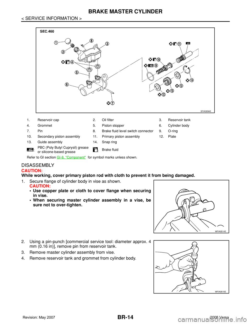
BR-14
< SERVICE INFORMATION >
BRAKE MASTER CYLINDER
DISASSEMBLY
CAUTION:
While working, cover primary piston rod with cloth to prevent it from being damaged.
1. Secure flange of cylinder body in vise as shown.
CAUTION:
• Use copper plate or cloth to cover flange when securing
in vise.
• When securing master cylinder assembly in a vise, be
sure not to over-tighten.
2. Using a pin-punch [commercial service tool: diameter approx. 4
mm (0.16 in)], remove pin from reservoir tank.
3. Remove master cylinder assembly from vise.
4. Remove reservoir tank and grommet from cylinder body.
1. Reservoir cap 2. Oil filter 3. Reservoir tank
4. Grommet 5. Piston stopper 6. Cylinder body
7. Pin 8. Brake fluid level switch connector 9. O-ring
10. Secondary piston assembly 11. Primary piston assembly 12. Plate
13. Guide assembly 14. Snap ring
:PBC (Poly Butyl Cuprysil) grease
or silicone-based grease:Brake fluid
Refer to GI section GI-8, "
Component" for symbol marks unless shown.
SFIA3094E
WFIA0514E
WFIA0515E