Page 1827 of 2771

FUEL LEVEL SENSOR UNIT, FUEL FILTER AND FUEL PUMP ASSEMBLY
FL-7
< SERVICE INFORMATION >
C
D
E
F
G
H
I
J
K
L
MA
FL
N
P O
Make sure that the fuel level sensor unit, fuel filter and fuel pump is free from defects and foreign materials.
INSTALLATION
Installation is in the reverse order of removal.
Fuel Level Sensor Unit, Fuel Filter and Fuel Pump Assembly
1. Install O-ring to fuel tank without twisting.
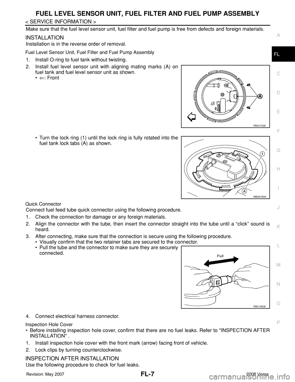
2. Install fuel level sensor unit with aligning mating marks (A) on
fuel tank and fuel level sensor unit as shown.
•⇐: Front
• Turn the lock ring (1) until the lock ring is fully rotated into the
fuel tank lock tabs (A) as shown.
Quick Connector
Connect fuel feed tube quick connector using the following procedure.
1. Check the connection for damage or any foreign materials.
2. Align the connector with the tube, then insert the connector straight into the tube until a “click” sound is
heard.
3. After connecting, make sure that the connection is secure using the following procedure.
• Visually confirm that the two retainer tabs are secured to the connector.
• Pull the tube and the connector to make sure they are securely
connected.
4. Connect electrical harness connector.
Inspection Hole Cover
• Before installing inspection hole cover, confirm that there are no fuel leaks. Refer to "INSPECTION AFTER
INSTALLATION" .
1. Install inspection hole cover with the front mark (arrow) facing front of vehicle.
2. Lock clips by turning counterclockwise.
INSPECTION AFTER INSTALLATION
Use the following procedure to check for fuel leaks.
PBIC4732E
WBIA0783E
PBIC1653E
Page 1828 of 2771
FL-8
< SERVICE INFORMATION >
FUEL LEVEL SENSOR UNIT, FUEL FILTER AND FUEL PUMP ASSEMBLY
1. Turn ignition switch “ON” (without starting the engine), to check the connections for fuel leaks with the
electric fuel pump applying pressure to the fuel piping.
2. Start the engine and let it idle to check that there are no fuel leaks at the fuel system connections.
Page 1998 of 2771
CAN COMMUNICATION SYSTEM
LAN-7
< FUNCTION DIAGNOSIS >[CAN FUNDAMENTAL]
C
D
E
F
G
H
I
J
L
MA
B
LAN
N
O
P
CAN Communication Control CircuitINFOID:0000000001711202
*: These are the only control units wired with both ends of CAN communication system.
SKIB8713E
Component System description
CAN controller It controls CAN communication signal transmission and reception, error detection, etc.
Transceiver ICIt converts digital signal into CAN communication signal, and CAN communication signal into digital
signal.
Noise filter It eliminates noise of CAN communication signal.
Termination circuit
*
(Resistance of approx. 120 Ω)It produces potential difference.
Page 2251 of 2771

LU-1
ENGINE
C
D
E
F
G
H
I
J
K
L
M
SECTION LU
A
LU
N
O
P
CONTENTS
ENGINE LUBRICATION SYSTEM
SERVICE INFORMATION ............................2
PRECAUTIONS ...................................................2
Precaution for Supplemental Restraint System
(SRS) "AIR BAG" and "SEAT BELT PRE-TEN-
SIONER" ...................................................................
2
Precaution for Liquid Gasket .....................................2
PREPARATION ...................................................3
Special Service Tool .................................................3
Commercial Service Tool ..........................................3
LUBRICATION SYSTEM ....................................5
Lubrication Circuit .....................................................5
ENGINE OIL .......................................................6
Inspection .................................................................6
Changing Engine Oil .................................................7
OIL FILTER ........................................................9
Removal and Installation ..........................................9
SERVICE DATA AND SPECIFICATIONS
(SDS) .................................................................
10
Standard and Limit ..................................................10
Page 2253 of 2771
PREPARATION
LU-3
< SERVICE INFORMATION >
C
D
E
F
G
H
I
J
K
L
MA
LU
N
P O
PREPARATION
Special Service ToolINFOID:0000000001702515
The actual shapes of Kent-Moore tools may differ from those of special service tools illustrated here.
Commercial Service ToolINFOID:0000000001702516
Tool number
(Kent-Moore No.)
Tool nameDescription
ST25051001
(J-25695-1)
Oil pressure gaugeMeasuring oil pressure
Maximum measuring range: 2,452 kPa (25
kg/cm
2, 356 psi)
ST25052000
(J-25695-2)
HoseAdapting oil pressure gauge to oil pan (upper)
KV10115801
(J-38956)
Oil filter wrenchRemoving oil filter
a: 64.3 mm (2.531 in)
WS39930000
(—)
Tube presserPressing the tube of liquid gasket
NT050
S-NT559
S-NT375
NT052
Page 2256 of 2771

LU-6
< SERVICE INFORMATION >
ENGINE OIL
ENGINE OIL
InspectionINFOID:0000000001702518
ENGINE OIL LEVEL
NOTE:
Before starting engine, park vehicle on a level surface and check the engine oil level. If engine is already
started, stop it and allow 10 minutes before checking.
1. Pull out oil level gauge and wipe it clean.
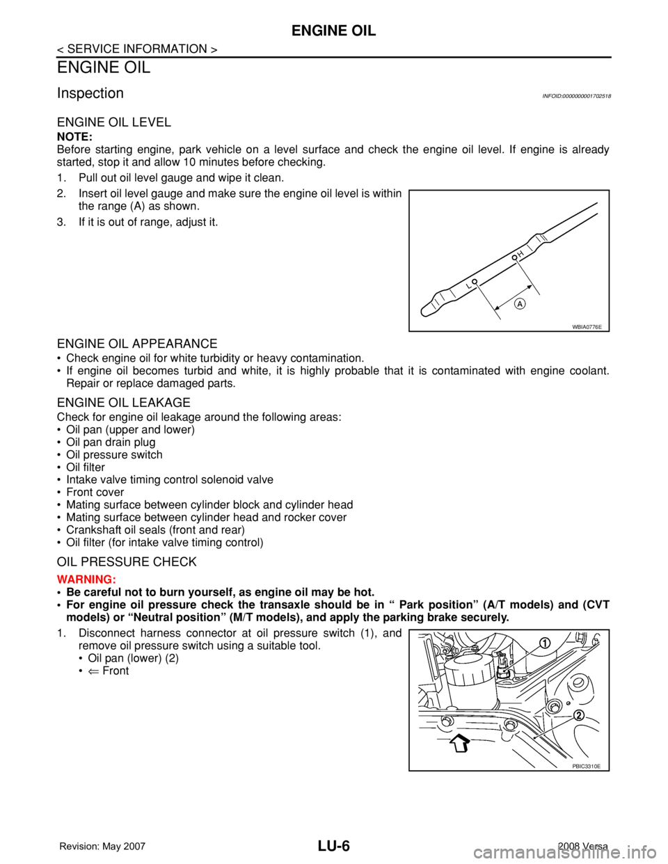
2. Insert oil level gauge and make sure the engine oil level is within
the range (A) as shown.
3. If it is out of range, adjust it.
ENGINE OIL APPEARANCE
• Check engine oil for white turbidity or heavy contamination.
• If engine oil becomes turbid and white, it is highly probable that it is contaminated with engine coolant.
Repair or replace damaged parts.
ENGINE OIL LEAKAGE
Check for engine oil leakage around the following areas:
• Oil pan (upper and lower)
• Oil pan drain plug
• Oil pressure switch
• Oil filter
• Intake valve timing control solenoid valve
• Front cover
• Mating surface between cylinder block and cylinder head
• Mating surface between cylinder head and rocker cover
• Crankshaft oil seals (front and rear)
• Oil filter (for intake valve timing control)
OIL PRESSURE CHECK
WARNING:
• Be careful not to burn yourself, as engine oil may be hot.
• For engine oil pressure check the transaxle should be in “ Park position” (A/T models) and (CVT
models) or “Neutral position” (M/T models), and apply the parking brake securely.
1. Disconnect harness connector at oil pressure switch (1), and
remove oil pressure switch using a suitable tool.
• Oil pan (lower) (2)
•⇐ Front
WBIA0776E
PBIC3310E
Page 2258 of 2771
LU-8
< SERVICE INFORMATION >
ENGINE OIL
3. Loosen oil filler cap (1) and then remove drain plug (2).
• Oil filter (3)
•⇐ Engine front
4. Drain engine oil.
5. Install drain plug (2) with new washer. Refer to EM-24, "
Compo-
nent".
CAUTION:
Be sure to clean drain plug (2) and install with new washer.
6. Refill with new engine oil.
Refer to MA-10
.
CAUTION:
• The refill capacity depends on the engine oil temperature
and drain time. Use these specifications for reference
only.
• Always use oil level gauge to determine the proper
amount of engine oil in the engine.
7. Warm up engine and check area around drain plug (2) and oil fil-
ter (3) for engine oil leakage.
8. Stop engine and wait for 10 minutes.
9. Check the engine oil level. Refer to LU-6, "
Inspection".
PBIC3915E
Page 2259 of 2771

OIL FILTER
LU-9
< SERVICE INFORMATION >
C
D
E
F
G
H
I
J
K
L
MA
LU
N
P O
OIL FILTER
Removal and InstallationINFOID:0000000001702520
REMOVAL
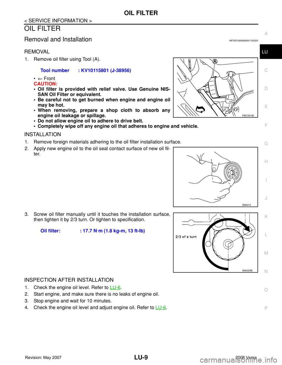
1. Remove oil filter using Tool (A).
•⇐ Front
CAUTION:
• Oil filter is provided with relief valve. Use Genuine NIS-
SAN Oil Filter or equivalent.
• Be careful not to get burned when engine and engine oil
may be hot.
• When removing, prepare a shop cloth to absorb any
engine oil leakage or spillage.
• Do not allow engine oil to adhere to drive belt.
• Completely wipe off any engine oil that adheres to engine and vehicle.
INSTALLATION
1. Remove foreign materials adhering to the oil filter installation surface.
2. Apply new engine oil to the oil seal contact surface of new oil fil-
ter.
3. Screw oil filter manually until it touches the installation surface,
then tighten it by 2/3 turn. Or tighten to specification.
INSPECTION AFTER INSTALLATION
1. Check the engine oil level. Refer to LU-6.
2. Start engine, and make sure there is no leaks of engine oil.
3. Stop engine and wait for 10 minutes.
4. Check the engine oil level and adjust engine oil. Refer to LU-6
. Tool number : KV10115801 (J-38956)
PBIC3818E
SMA010
Oil filter: : 17.7 N·m (1.8 kg-m, 13 ft-lb)
SMA229B