2008 NISSAN LATIO Filter
[x] Cancel search: FilterPage 1732 of 2771
CAMSHAFT
EM-55
< SERVICE INFORMATION >
C
D
E
F
G
H
I
J
K
L
MA
EM
N
P O
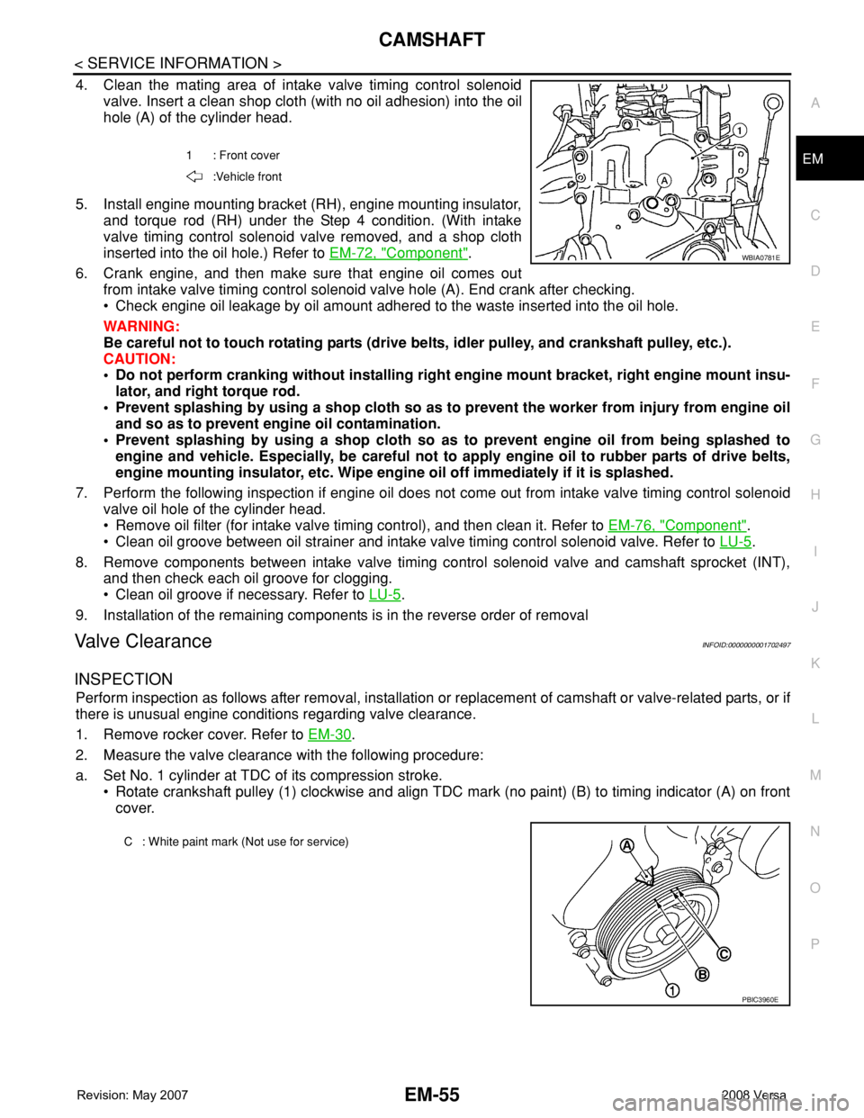
4. Clean the mating area of intake valve timing control solenoid
valve. Insert a clean shop cloth (with no oil adhesion) into the oil
hole (A) of the cylinder head.
5. Install engine mounting bracket (RH), engine mounting insulator,
and torque rod (RH) under the Step 4 condition. (With intake
valve timing control solenoid valve removed, and a shop cloth
inserted into the oil hole.) Refer to EM-72, "
Component".
6. Crank engine, and then make sure that engine oil comes out
from intake valve timing control solenoid valve hole (A). End crank after checking.
• Check engine oil leakage by oil amount adhered to the waste inserted into the oil hole.
WARNING:
Be careful not to touch rotating parts (drive belts, idler pulley, and crankshaft pulley, etc.).
CAUTION:
• Do not perform cranking without installing right engine mount bracket, right engine mount insu-
lator, and right torque rod.
• Prevent splashing by using a shop cloth so as to prevent the worker from injury from engine oil
and so as to prevent engine oil contamination.
• Prevent splashing by using a shop cloth so as to prevent engine oil from being splashed to
engine and vehicle. Especially, be careful not to apply engine oil to rubber parts of drive belts,
engine mounting insulator, etc. Wipe engine oil off immediately if it is splashed.
7. Perform the following inspection if engine oil does not come out from intake valve timing control solenoid
valve oil hole of the cylinder head.
• Remove oil filter (for intake valve timing control), and then clean it. Refer to EM-76, "
Component".
• Clean oil groove between oil strainer and intake valve timing control solenoid valve. Refer to LU-5
.
8. Remove components between intake valve timing control solenoid valve and camshaft sprocket (INT),
and then check each oil groove for clogging.
• Clean oil groove if necessary. Refer to LU-5
.
9. Installation of the remaining components is in the reverse order of removal
Valve ClearanceINFOID:0000000001702497
INSPECTION
Perform inspection as follows after removal, installation or replacement of camshaft or valve-related parts, or if
there is unusual engine conditions regarding valve clearance.
1. Remove rocker cover. Refer to EM-30
.
2. Measure the valve clearance with the following procedure:
a. Set No. 1 cylinder at TDC of its compression stroke.
• Rotate crankshaft pulley (1) clockwise and align TDC mark (no paint) (B) to timing indicator (A) on front
cover.
1 : Front cover
:Vehicle front
WBIA0781E
C : White paint mark (Not use for service)
PBIC3960E
Page 1753 of 2771
EM-76
< SERVICE INFORMATION >
CYLINDER BLOCK
CYLINDER BLOCK
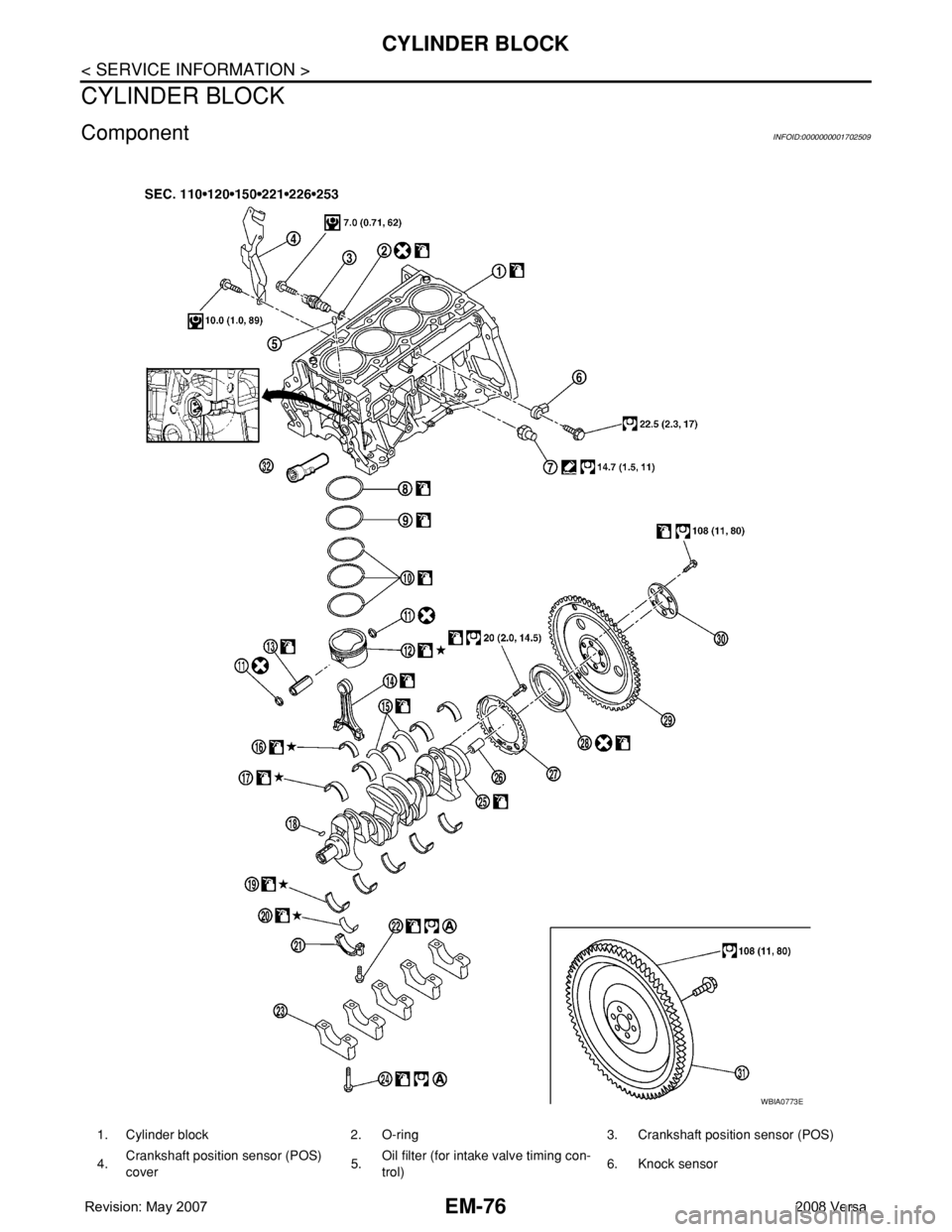
ComponentINFOID:0000000001702509
1. Cylinder block 2. O-ring 3. Crankshaft position sensor (POS)
4.Crankshaft position sensor (POS)
cover5.Oil filter (for intake valve timing con-
trol)6. Knock sensor
WBIA0773E
Page 1755 of 2771
EM-78
< SERVICE INFORMATION >
CYLINDER BLOCK
CAUTION:
• Avoid impacts such as a dropping.
• Never disassemble.
• Keep it away from metal particles.
• Never place sensor in a location where it is exposed to magnetism.
8. Remove oil filter (for intake valve timing control).
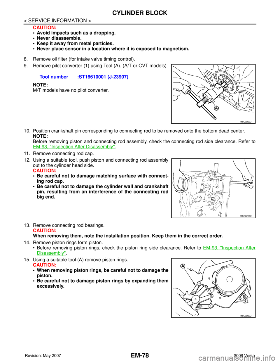
9. Remove pilot converter (1) using Tool (A). (A/T or CVT models)
NOTE:
M/T models have no pilot converter.
10. Position crankshaft pin corresponding to connecting rod to be removed onto the bottom dead center.
NOTE:
Before removing piston and connecting rod assembly, check the connecting rod side clearance. Refer to
EM-93, "
Inspection After Disassembly".
11. Remove connecting rod cap.
12. Using a suitable tool, push piston and connecting rod assembly
out to the cylinder head side.
CAUTION:
• Be careful not to damage matching surface with connect-
ing rod cap.
• Be careful not to damage the cylinder wall and crankshaft
pin, resulting from an interference of the connecting rod
big end.
13. Remove connecting rod bearings.
CAUTION:
When removing them, note the installation position. Keep them in the correct order.
14. Remove piston rings form piston.
• Before removing piston rings, check the piston ring side clearance. Refer to EM-93, "
Inspection After
Disassembly".
15. Using a suitable tool (A) remove piston rings.
CAUTION:
• When removing piston rings, be careful not to damage the
piston.
• Be careful not to damage piston rings by expanding them
excessively.Tool number :ST16610001 (J-23907)
PBIC3229J
PBIC0259E
PBIC3233J
Page 1762 of 2771
CYLINDER BLOCK
EM-85
< SERVICE INFORMATION >
C
D
E
F
G
H
I
J
K
L
MA
EM
N
P O
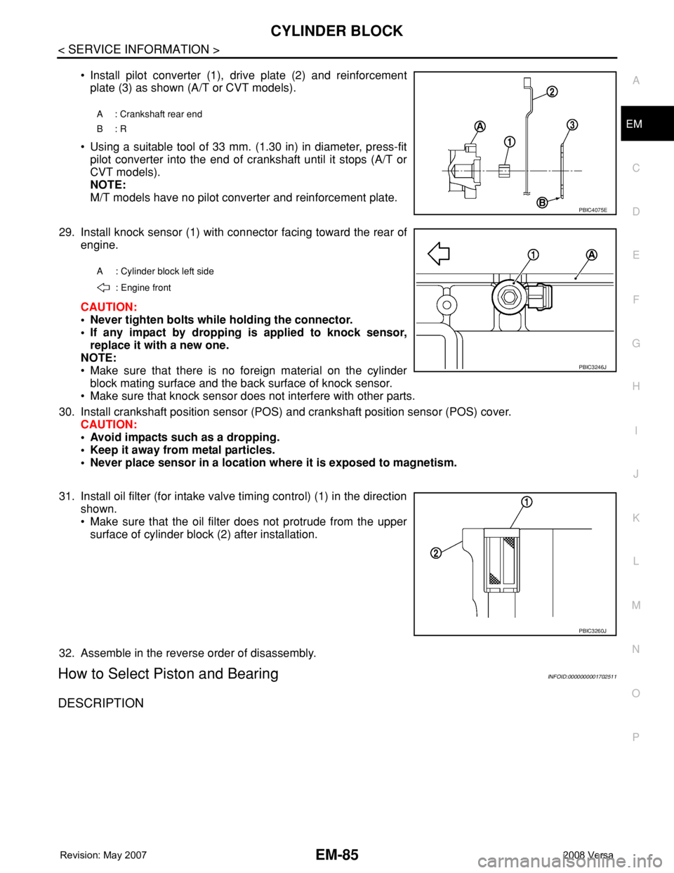
• Install pilot converter (1), drive plate (2) and reinforcement
plate (3) as shown (A/T or CVT models).
• Using a suitable tool of 33 mm. (1.30 in) in diameter, press-fit
pilot converter into the end of crankshaft until it stops (A/T or
CVT models).
NOTE:
M/T models have no pilot converter and reinforcement plate.
29. Install knock sensor (1) with connector facing toward the rear of
engine.
CAUTION:
• Never tighten bolts while holding the connector.
• If any impact by dropping is applied to knock sensor,
replace it with a new one.
NOTE:
• Make sure that there is no foreign material on the cylinder
block mating surface and the back surface of knock sensor.
• Make sure that knock sensor does not interfere with other parts.
30. Install crankshaft position sensor (POS) and crankshaft position sensor (POS) cover.
CAUTION:
• Avoid impacts such as a dropping.
• Keep it away from metal particles.
• Never place sensor in a location where it is exposed to magnetism.
31. Install oil filter (for intake valve timing control) (1) in the direction
shown.
• Make sure that the oil filter does not protrude from the upper
surface of cylinder block (2) after installation.
32. Assemble in the reverse order of disassembly.
How to Select Piston and BearingINFOID:0000000001702511
DESCRIPTION
A : Crankshaft rear end
B: R
PBIC4075E
A : Cylinder block left side
: Engine front
PBIC3246J
PBIC3260J
Page 1779 of 2771
EM-102
< SERVICE INFORMATION >
CYLINDER BLOCK
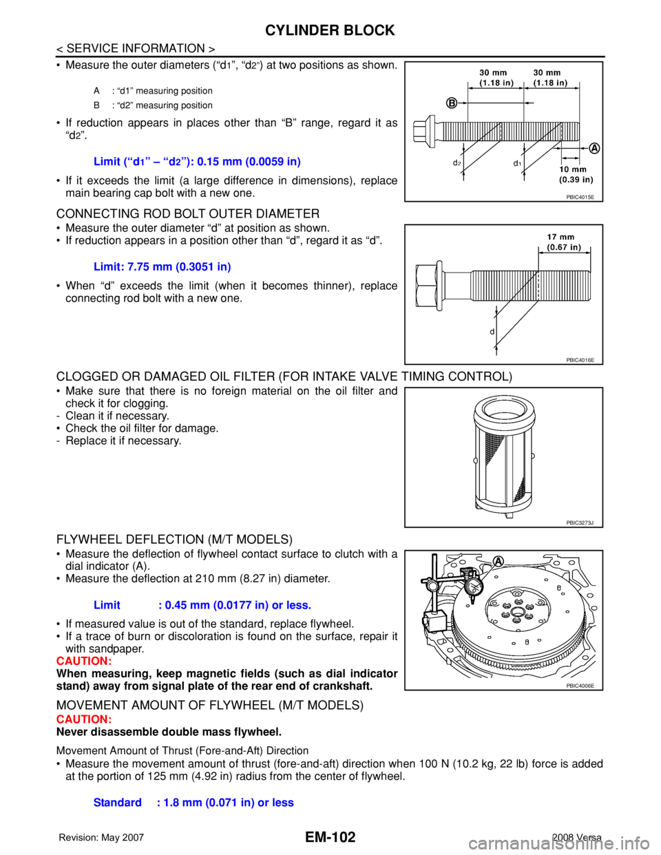
• Measure the outer diameters (“d1”, “d2”) at two positions as shown.
• If reduction appears in places other than “B” range, regard it as
“d
2”.
• If it exceeds the limit (a large difference in dimensions), replace
main bearing cap bolt with a new one.
CONNECTING ROD BOLT OUTER DIAMETER
• Measure the outer diameter “d” at position as shown.
• If reduction appears in a position other than “d”, regard it as “d”.
• When “d” exceeds the limit (when it becomes thinner), replace
connecting rod bolt with a new one.
CLOGGED OR DAMAGED OIL FILTER (FOR INTAKE VALVE TIMING CONTROL)
• Make sure that there is no foreign material on the oil filter and
check it for clogging.
- Clean it if necessary.
• Check the oil filter for damage.
- Replace it if necessary.
FLYWHEEL DEFLECTION (M/T MODELS)
• Measure the deflection of flywheel contact surface to clutch with a
dial indicator (A).
• Measure the deflection at 210 mm (8.27 in) diameter.
• If measured value is out of the standard, replace flywheel.
• If a trace of burn or discoloration is found on the surface, repair it
with sandpaper.
CAUTION:
When measuring, keep magnetic fields (such as dial indicator
stand) away from signal plate of the rear end of crankshaft.
MOVEMENT AMOUNT OF FLYWHEEL (M/T MODELS)
CAUTION:
Never disassemble double mass flywheel.
Movement Amount of Thrust (Fore-and-Aft) Direction
• Measure the movement amount of thrust (fore-and-aft) direction when 100 N (10.2 kg, 22 lb) force is added
at the portion of 125 mm (4.92 in) radius from the center of flywheel.
A : “d1” measuring position
B : “d2” measuring position
Limit (“d1” – “d2”): 0.15 mm (0.0059 in)
PBIC4015E
Limit: 7.75 mm (0.3051 in)
PBIC4016E
PBIC3273J
Limit : 0.45 mm (0.0177 in) or less.
PBIC4006E
Standard : 1.8 mm (0.071 in) or less
Page 1821 of 2771
FL-1
ENGINE
C
D
E
F
G
H
I
J
K
L
M
SECTION FL
A
FL
N
O
P
CONTENTS
FUEL SYSTEM
SERVICE INFORMATION ............................2
PRECAUTIONS ...................................................2
Precaution for Supplemental Restraint System
(SRS) "AIR BAG" and "SEAT BELT PRE-TEN-
SIONER" ...................................................................
2
PREPARATION ...................................................3
Special Service Tool .................................................3
Commercial Service Tool ..........................................3
FUEL SYSTEM ....................................................4
Checking Fuel Line ...................................................4
General Precaution ...................................................4
FUEL LEVEL SENSOR UNIT, FUEL FILTER
AND FUEL PUMP ASSEMBLY .........................
5
Component ...............................................................5
Removal and Installation ..........................................5
FUEL TANK .......................................................9
Component ...............................................................9
Removal and Installation ..........................................9
SERVICE DATA AND SPECIFICATIONS
(SDS) .................................................................
14
Standard and Limit ..................................................14
Page 1825 of 2771
FUEL LEVEL SENSOR UNIT, FUEL FILTER AND FUEL PUMP ASSEMBLY
FL-5
< SERVICE INFORMATION >
C
D
E
F
G
H
I
J
K
L
MA
FL
N
P O
FUEL LEVEL SENSOR UNIT, FUEL FILTER AND FUEL PUMP ASSEMBLY
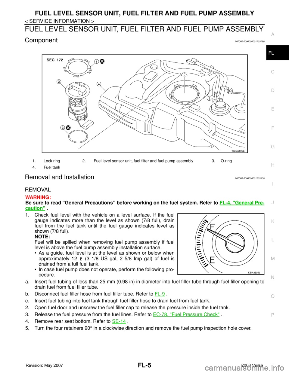
ComponentINFOID:0000000001703099
Removal and InstallationINFOID:0000000001703100
REMOVAL
WARNING:
Be sure to read “General Precautions” before working on the fuel system. Refer to FL-4, "
General Pre-
caution" .
1. Check fuel level with the vehicle on a level surface. If the fuel
gauge indicates more than the level as shown (7/8 full), drain
fuel from the fuel tank until the fuel gauge indicates level as
shown (7/8 full).
NOTE:
Fuel will be spilled when removing fuel pump assembly if fuel
level is above the fuel pump assembly installation surface.
• As a guide, fuel level is at the level as shown or below when
approximately 12 (3 1/8 US gal, 2 5/8 Imp gal) of fuel is
drained from a full fuel tank.
• In case fuel pump does not operate, perform the following pro-
cedure.
a. Insert fuel tubing of less than 25 mm (0.98 in) in diameter into fuel filler tube through fuel filler opening to
drain fuel from fuel filler tube.
b. Disconnect fuel filler hose from fuel filler tube. Refer to FL-9
.
c. Insert fuel tubing into fuel tank through fuel filler hose to drain fuel from fuel tank.
2. Open fuel door and unscrew the fuel filler cap to release the pressure inside the fuel tank.
3. Release the fuel pressure from the fuel lines. Refer to EC-78, "
Fuel Pressure Check" .
4. Remove rear seat bottom. Refer to SE-14
.
5. Turn the four retainers 90° in a clockwise direction and remove the fuel pump inspection hole cover.
1. Lock ring 2. Fuel level sensor unit, fuel filter and fuel pump assembly 3. O-ring
4. Fuel tank
WCIA0590E
KBIA3505J
Page 1826 of 2771
FL-6
< SERVICE INFORMATION >
FUEL LEVEL SENSOR UNIT, FUEL FILTER AND FUEL PUMP ASSEMBLY
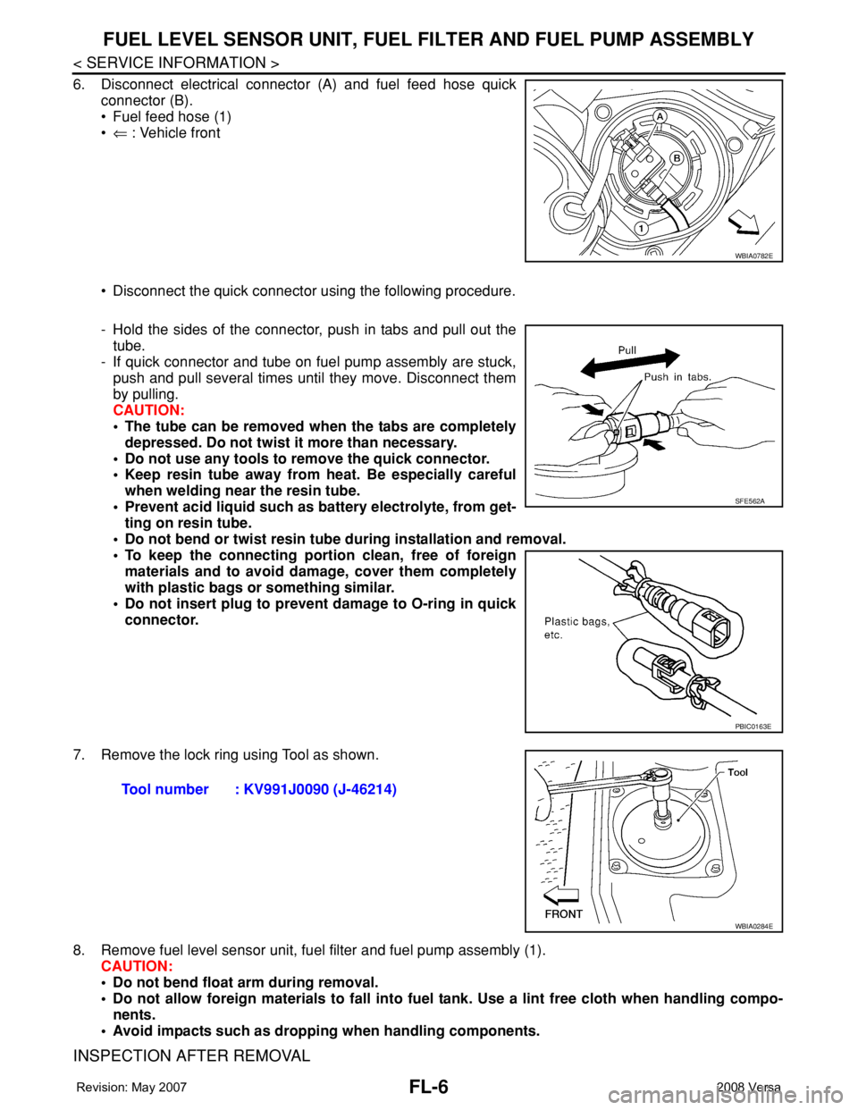
6. Disconnect electrical connector (A) and fuel feed hose quick
connector (B).
• Fuel feed hose (1)
•⇐ : Vehicle front
• Disconnect the quick connector using the following procedure.
- Hold the sides of the connector, push in tabs and pull out the
tube.
- If quick connector and tube on fuel pump assembly are stuck,
push and pull several times until they move. Disconnect them
by pulling.
CAUTION:
• The tube can be removed when the tabs are completely
depressed. Do not twist it more than necessary.
• Do not use any tools to remove the quick connector.
• Keep resin tube away from heat. Be especially careful
when welding near the resin tube.
• Prevent acid liquid such as battery electrolyte, from get-
ting on resin tube.
• Do not bend or twist resin tube during installation and removal.
• To keep the connecting portion clean, free of foreign
materials and to avoid damage, cover them completely
with plastic bags or something similar.
• Do not insert plug to prevent damage to O-ring in quick
connector.
7. Remove the lock ring using Tool as shown.
8. Remove fuel level sensor unit, fuel filter and fuel pump assembly (1).
CAUTION:
• Do not bend float arm during removal.
• Do not allow foreign materials to fall into fuel tank. Use a lint free cloth when handling compo-
nents.
• Avoid impacts such as dropping when handling components.
INSPECTION AFTER REMOVAL
WBIA0782E
SFE562A
PBIC0163E
Tool number : KV991J0090 (J-46214)
WBIA0284E