2008 NISSAN LATIO sensor
[x] Cancel search: sensorPage 799 of 2771
![NISSAN LATIO 2008 Service Repair Manual BRC-34
< SERVICE INFORMATION >[ABS]
SENSOR ROTOR
SENSOR ROTOR
Removal and InstallationINFOID:0000000001703851
Sensor rotor cannot be disassembled. To replace sensor rotor, replace hub bearing assembly NISSAN LATIO 2008 Service Repair Manual BRC-34
< SERVICE INFORMATION >[ABS]
SENSOR ROTOR
SENSOR ROTOR
Removal and InstallationINFOID:0000000001703851
Sensor rotor cannot be disassembled. To replace sensor rotor, replace hub bearing assembly](/manual-img/5/57360/w960_57360-798.png)
BRC-34
< SERVICE INFORMATION >[ABS]
SENSOR ROTOR
SENSOR ROTOR
Removal and InstallationINFOID:0000000001703851
Sensor rotor cannot be disassembled. To replace sensor rotor, replace hub bearing assembly. Refer to FAX-5
in “FAX” section, refer to RAX-4 in “RAX” section.
Page 836 of 2771

WATER OUTLET AND WATER CONTROL VALVE
CO-19
< SERVICE INFORMATION >
C
D
E
F
G
H
I
J
K
L
MA
CO
N
P O
WATER OUTLET AND WATER CONTROL VALVE
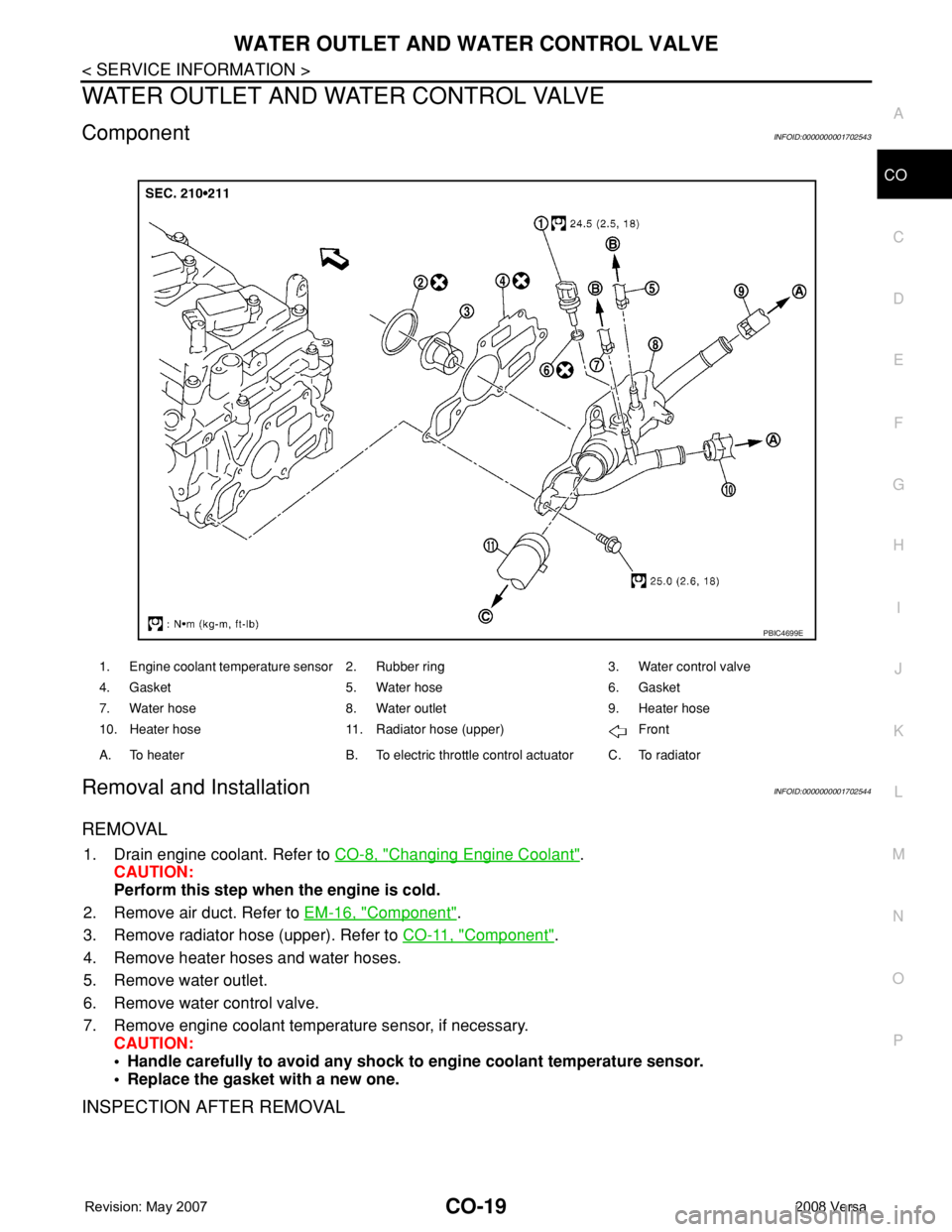
ComponentINFOID:0000000001702543
Removal and InstallationINFOID:0000000001702544
REMOVAL
1. Drain engine coolant. Refer to CO-8, "Changing Engine Coolant".
CAUTION:
Perform this step when the engine is cold.
2. Remove air duct. Refer to EM-16, "
Component".
3. Remove radiator hose (upper). Refer to CO-11, "
Component".
4. Remove heater hoses and water hoses.
5. Remove water outlet.
6. Remove water control valve.
7. Remove engine coolant temperature sensor, if necessary.
CAUTION:
• Handle carefully to avoid any shock to engine coolant temperature sensor.
• Replace the gasket with a new one.
INSPECTION AFTER REMOVAL
1. Engine coolant temperature sensor 2. Rubber ring 3. Water control valve
4. Gasket 5. Water hose 6. Gasket
7. Water hose 8. Water outlet 9. Heater hose
10. Heater hose 11. Radiator hose (upper) Front
A. To heater B. To electric throttle control actuator C. To radiator
PBIC4699E
Page 841 of 2771

CVT-2
Description ..............................................................60
CONSULT-III Reference Value in Data Monitor
Mode .......................................................................
60
On Board Diagnosis Logic ......................................60
Possible Cause .......................................................60
DTC Confirmation Procedure .................................60
Wiring Diagram - CVT - STSIG ...............................61
Diagnosis Procedure ..............................................62
DTC P0703 STOP LAMP SWITCH CIRCUIT ....63
Description ..............................................................63
CONSULT-III Reference Value in Data Monitor
Mode .......................................................................
63
On Board Diagnosis Logic ......................................63
Possible Cause .......................................................63
DTC Confirmation Procedure .................................63
Diagnosis Procedure ..............................................63
DTC P0705 PARK/NEUTRAL POSITION
SWITCH .............................................................
65
Description ..............................................................65
CONSULT-III Reference Value in Data Monitor
Mode .......................................................................
65
On Board Diagnosis Logic ......................................65
Possible Cause .......................................................65
DTC Confirmation Procedure .................................65
Wiring Diagram - CVT - PNP/SW ...........................67
Diagnosis Procedure ..............................................68
Component Inspection ............................................70
DTC P0710 CVT FLUID TEMPERATURE
SENSOR CIRCUIT .............................................
71
Description ..............................................................71
CONSULT-III Reference Value in Data Monitor
Mode .......................................................................
71
On Board Diagnosis Logic ......................................71
Possible Cause .......................................................71
DTC Confirmation Procedure .................................71
Wiring Diagram - CVT - FTS ...................................72
Diagnosis Procedure ..............................................73
Component Inspection ............................................74
DTC P0715 INPUT SPEED SENSOR CIR-
CUIT (PRI SPEED SENSOR) ............................
76
Description ..............................................................76
CONSULT-III Reference Value in Data Monitor
Mode .......................................................................
76
On Board Diagnosis Logic ......................................76
Possible Cause .......................................................76
DTC Confirmation Procedure .................................76
Wiring Diagram - CVT - PRSCVT ...........................77
Diagnosis Procedure ..............................................78
DTC P0720 VEHICLE SPEED SENSOR CVT
(SECONDARY SPEED SENSOR) .....................
80
Description ..............................................................80
CONSULT-III Reference Value in Data Monitor
Mode .......................................................................
80
On Board Diagnosis Logic ......................................80
Possible Cause .......................................................80
DTC Confirmation Procedure ..................................80
Wiring Diagram - CVT - SESCVT ...........................81
Diagnosis Procedure ...............................................82
DTC P0725 ENGINE SPEED SIGNAL ..............85
Description ..............................................................85
CONSULT-III Reference Value in Data Monitor
Mode .......................................................................
85
On Board Diagnosis Logic ......................................85
Possible Cause .......................................................85
DTC Confirmation Procedure ..................................85
Diagnosis Procedure ...............................................85
DTC P0730 BELT DAMAGE .............................87
Description ..............................................................87
CONSULT-III Reference Value in Data Monitor
Mode .......................................................................
87
On Board Diagnosis Logic ......................................87
Possible Cause .......................................................87
DTC Confirmation Procedure ..................................87
Diagnosis Procedure ...............................................87
DTC P0740 TORQUE CONVERTER CLUTCH
SOLENOID VALVE ...........................................
88
Description ..............................................................88
CONSULT-III Reference Value in Data Monitor
Mode .......................................................................
88
On Board Diagnosis Logic ......................................88
Possible Cause .......................................................88
DTC Confirmation Procedure ..................................88
Wiring Diagram - CVT - TCV ..................................89
Diagnosis Procedure ...............................................90
Component Inspection ............................................91
DTC P0744 A/T TCC S/V FUNCTION (LOCK-
UP) .....................................................................
93
Description ..............................................................93
CONSULT-III Reference Value in Data Monitor
Mode .......................................................................
93
On Board Diagnosis Logic ......................................93
Possible Cause .......................................................93
DTC Confirmation Procedure ..................................93
Diagnosis Procedure ...............................................93
DTC P0745 LINE PRESSURE SOLENOID
VALVE ...............................................................
95
Description ..............................................................95
CONSULT-III Reference Value in Data Monitor
Mode .......................................................................
95
On Board Diagnosis Logic ......................................95
Possible Cause .......................................................95
DTC Confirmation Procedure ..................................95
Wiring Diagram - CVT - LPSV ................................96
Diagnosis Procedure ...............................................97
Component Inspection ............................................98
DTC P0746 PRESSURE CONTROL SOLE-
NOID A PERFORMANCE (LINE PRESSURE
SOLENOID VALVE) .........................................
100
Description ............................................................100
Page 842 of 2771

CVT-3
D
E
F
G
H
I
J
K
L
MA
B
CVT
N
O
P N CONSULT-III Reference Value in Data Monitor
Mode .....................................................................
100
On Board Diagnosis Logic ....................................100
Possible Cause .....................................................100
DTC Confirmation Procedure ................................100
Diagnosis Procedure .............................................100
DTC P0776 PRESSURE CONTROL SOLE-
NOID B PERFORMANCE (SEC PRESSURE
SOLENOID VALVE) .........................................
102
Description ............................................................102
CONSULT-III Reference Value in Data Monitor
Mode .....................................................................
102
On Board Diagnosis Logic ....................................102
Possible Cause .....................................................102
DTC Confirmation Procedure ................................102
Diagnosis Procedure .............................................102
DTC P0778 PRESSURE CONTROL SOLE-
NOID B ELECTRICAL (SEC PRESSURE SO-
LENOID VALVE) ..............................................
104
Description ............................................................104
CONSULT-III Reference Value in Data Monitor
Mode .....................................................................
104
On Board Diagnosis Logic ....................................104
Possible Cause .....................................................104
DTC Confirmation Procedure ................................104
Wiring Diagram - CVT - SECPSV .........................105
Diagnosis Procedure .............................................106
Component Inspection ..........................................107
DTC P0840 TRANSMISSION FLUID PRES-
SURE SENSOR A CIRCUIT (SEC PRES-
SURE SENSOR) ...............................................
109
Description ............................................................109
CONSULT-III Reference Value in Data Monitor
Mode .....................................................................
109
On Board Diagnosis Logic ....................................109
Possible Cause .....................................................109
DTC Confirmation Procedure ................................109
Wiring Diagram - CVT - SECPS ............................110
Diagnosis Procedure .............................................111
DTC P0841 PRESSURE SENSOR FUNC-
TION .................................................................
113
Description ............................................................113
CONSULT-III Reference Value in Data Monitor
Mode .....................................................................
113
On Board Diagnosis Logic ....................................113
Possible Cause .....................................................113
DTC Confirmation Procedure ................................113
Diagnosis Procedure .............................................113
DTC P0845 TRANSMISSION FLUID PRES-
SURE SENSOR B CIRCUIT (PRI PRESSURE
SENSOR) ..........................................................
115
Description ............................................................115
CONSULT-III Reference Value in Data Monitor
Mode .....................................................................
115
On Board Diagnosis Logic .....................................115
Possible Cause ......................................................115
DTC Confirmation Procedure ................................115
Wiring Diagram - CVT - PRIPS .............................116
Diagnosis Procedure .............................................117
DTC P0868 SECONDARY PRESSURE
DOWN .............................................................
119
Description .............................................................119
CONSULT-III Reference Value in Data Monitor
Mode ......................................................................
119
On Board Diagnosis Logic .....................................119
Possible Cause ......................................................119
DTC Confirmation Procedure ................................119
Diagnosis Procedure .............................................119
DTC P1701 TRANSMISSION CONTROL
MODULE (POWER SUPPLY) .........................
121
Description .............................................................121
On Board Diagnosis Logic .....................................121
Possible Cause ......................................................121
DTC Confirmation Procedure ................................121
Wiring Diagram - CVT - POWER ...........................122
Diagnosis Procedure .............................................123
DTC P1705 THROTTLE POSITION SENSOR .125
Description .............................................................125
CONSULT-III Reference Value in Data Monitor
Mode ......................................................................
125
On Board Diagnosis Logic .....................................125
Possible Cause ......................................................125
DTC Confirmation Procedure ................................125
Diagnosis Procedure .............................................125
DTC P1722 ESTM VEHICLE SPEED SIGNAL .127
Description .............................................................127
CONSULT-III Reference Value in Data Monitor
Mode ......................................................................
127
On Board Diagnosis Logic .....................................127
Possible Cause ......................................................127
DTC Confirmation Procedure ................................127
Diagnosis Procedure .............................................127
DTC P1723 CVT SPEED SENSOR FUNC-
TION ................................................................
129
Description .............................................................129
On Board Diagnosis Logic .....................................129
Possible Cause ......................................................129
DTC Confirmation Procedure ................................129
Diagnosis Procedure .............................................129
DTC P1726 ELECTRIC THROTTLE CON-
TROL SYSTEM ...............................................
131
Description .............................................................131
On Board Diagnosis Logic .....................................131
Possible Cause ......................................................131
DTC Confirmation Procedure ................................131
Diagnosis Procedure .............................................131
Page 843 of 2771

CVT-4
DTC P1740 LOCK-UP SELECT SOLENOID
VALVE CIRCUIT ..............................................
132
Description .............................................................132
CONSULT-III Reference Value in Data Monitor
Mode ......................................................................
132
On Board Diagnosis Logic .....................................132
Possible Cause ......................................................132
DTC Confirmation Procedure ................................132
Wiring Diagram - CVT - L/USSV ............................133
Diagnosis Procedure .............................................134
Component Inspection ...........................................135
DTC P1745 LINE PRESSURE CONTROL ......136
Description .............................................................136
On Board Diagnosis Logic .....................................136
Possible Cause ......................................................136
DTC Confirmation Procedure ................................136
Diagnosis Procedure .............................................136
DTC P1777 STEP MOTOR - CIRCUIT ............137
Description .............................................................137
CONSULT-III Reference Value in Data Monitor
Mode ......................................................................
137
On Board Diagnosis Logic .....................................137
Possible Cause ......................................................137
DTC Confirmation Procedure ................................137
Wiring Diagram - CVT - STM .................................138
Diagnosis Procedure .............................................139
Component Inspection ...........................................140
DTC P1778 STEP MOTOR - FUNCTION ........141
Description .............................................................141
CONSULT-III Reference Value in Data Monitor
Mode ......................................................................
141
On Board Diagnosis Logic .....................................141
Possible Cause ......................................................141
DTC Confirmation Procedure ................................141
Diagnosis Procedure .............................................142
OVERDRIVE CONTROL SWITCH ..................143
Description .............................................................143
CONSULT-III Reference Value in Data Monitor
Mode ......................................................................
143
Wiring Diagram - CVT - ODSW .............................144
Diagnosis Procedure .............................................144
Component Inspection ...........................................146
SHIFT POSITION INDICATOR CIRCUIT ........148
Description .............................................................148
CONSULT-III Reference Value in Data Monitor
Mode ......................................................................
148
Diagnosis Procedure .............................................148
TROUBLE DIAGNOSIS FOR SYMPTOMS .....149
Wiring Diagram - CVT - NONDTC .........................149
O/D OFF Indicator Lamp Does Not Come On ......151
Engine Cannot Be Started in "P" and "N" Position .153
In "P" Position, Vehicle Moves Forward or Back-
ward When Pushed ...............................................
153
In "N" Position, Vehicle Moves ..............................154
Large Shock "N" → "R" Position ...........................154
Vehicle Does Not Creep Backward in "R" Position .155
Vehicle Does Not Creep Forward in "D" or "L" Po-
sition ......................................................................
156
Vehicle Speed Does Not Change in "L" Position ..157
Vehicle Speed Does Not Change in overdrive-off
mode .....................................................................
158
Vehicle Speed Does Not Change in "D" Position .159
Vehicle Does Not Decelerate by Engine Brake ....159
TRANSMISSION CONTROL MODULE ...........161
Removal and Installation .......................................161
CVT SHIFT LOCK SYSTEM .............................162
Description ............................................................162
Shift Lock System Electrical Parts Location ..........162
Wiring Diagram - CVT - SHIFT .............................163
Diagnosis Procedure .............................................163
SHIFT CONTROL SYSTEM .............................167
Removal and Installation .......................................167
Control Device Disassembly and Assembly .........170
Selector Lever Knob Removal and Installation .....170
Adjustment of CVT Position ..................................171
Checking of CVT Position .....................................171
KEY INTERLOCK CABLE ...............................173
Removal and Installation .......................................173
AIR BREATHER HOSE ....................................176
Removal and Installation .......................................176
DIFFERENTIAL SIDE OIL SEAL .....................177
Removal and Installation .......................................177
TRANSAXLE ASSEMBLY ...............................178
Removal and Installation .......................................178
SERVICE DATA AND SPECIFICATIONS
(SDS) ................................................................
181
General Specification ............................................181
Vehicle Speed When Shifting Gears .....................181
Stall Speed ............................................................181
Line Pressure ........................................................181
Solenoid Valves ....................................................182
CVT Fluid Temperature Sensor ............................182
Primary Speed Sensor ..........................................182
Secondary Speed Sensor .....................................182
Removal and Installation .......................................182
Page 847 of 2771

CVT-8
< SERVICE INFORMATION >
PRECAUTIONS
• Be sure to turn the ignition switch OFF and disconnect the battery cable from the negative terminal
before any repair or inspection work. The open/short circuit of related switches, sensors, solenoid
valves, etc. will cause the MIL to light up.
• Be sure to connect and lock the connectors securely after work. A loose (unlocked) connector will
cause the MIL to light up due to an open circuit. (Be sure the connector is free from water, grease,
dirt, bent terminals, etc.)
• Be sure to route and secure the harnesses properly after work. Interference of the harness with a
bracket, etc. may cause the MIL to light up due to a short circuit.
• Be sure to connect rubber tubes properly after work. A misconnected or disconnected rubber tube
may cause the MIL to light up due to a malfunction of the EVAP system or fuel injection system, etc.
• Be sure to erase the unnecessary malfunction information (repairs completed) from the TCM and
ECM before returning the vehicle to the customer.
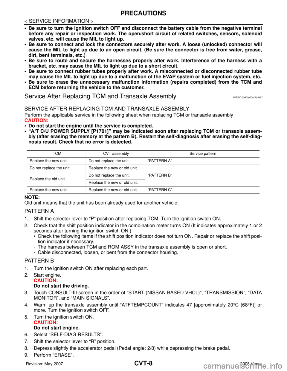
Service After Replacing TCM and Transaxle AssemblyINFOID:0000000001703427
SERVICE AFTER REPLACING TCM AND TRANSAXLE ASSEMBLY
Perform the applicable service in the following sheet when replacing TCM or transaxle assembly
CAUTION:
• Do not start the engine until the service is completed.
• “A/T C/U POWER SUPPLY [P1701]” may be indicated soon after replacing TCM or transaxle assem-
bly (after erasing the memory at the pattern B). Restart the self-diagnosis after erasing the self-diag-
nosis result. Check that no error is detected.
NOTE:
Old unit means that the unit has been already used for another vehicle.
PATTERN A
1. Shift the selector lever to “P” position after replacing TCM. Turn the ignition switch ON.
2. Check that the shift position indicator in the combination meter turns ON (It indicates approximately 1 or 2
seconds after turning the ignition switch ON.)
• Check the following items if the shift position indicator does not turn ON. Repair or replace the shift posi-
tion indicator if necessary.
- The harness between TCM and ROM ASSY in the transaxle assembly is open or short.
- Cable disconnected, loosen, or bent from the connector housing.
PATTERN B
1. Turn the ignition switch ON after replacing each part.
2. Start engine.
CAUTION:
Do not start the driving.
3. Touch CONSULT-III screen in the order of “START (NISSAN BASED VHCL)”, “TRANSMISSION”, “DATA
MONITOR”, and “MAIN SIGNALS”.
4. Warm up the transaxle assembly until “ATFTEMPCOUNT” indicates 47 [approximately 20°C (68°F)] or
more. Turn the ignition switch OFF.
5. Turn the ignition switch ON.
CAUTION:
Do not start engine.
6. Select “SELF-DIAG RESULTS”.
7. Shift the selector lever to “R” position.
8. Depress slightly the accelerator pedal (Pedal angle: 2/8) while depressing the brake pedal.
9. Perform “ERASE”.
TCM CVT assemblyService pattern
Replace the new unit. Do not replace the unit. "PATTERN A"
Do not replace the unit. Replace the new or old unit.
"PATTERN B"
Replace the old unit.Do not replace the unit.
Replace the new or old unit.
Replace the new unit. Replace the new or old unit. "PATTERN C"
Page 859 of 2771

CVT-20
< SERVICE INFORMATION >
CVT SYSTEM
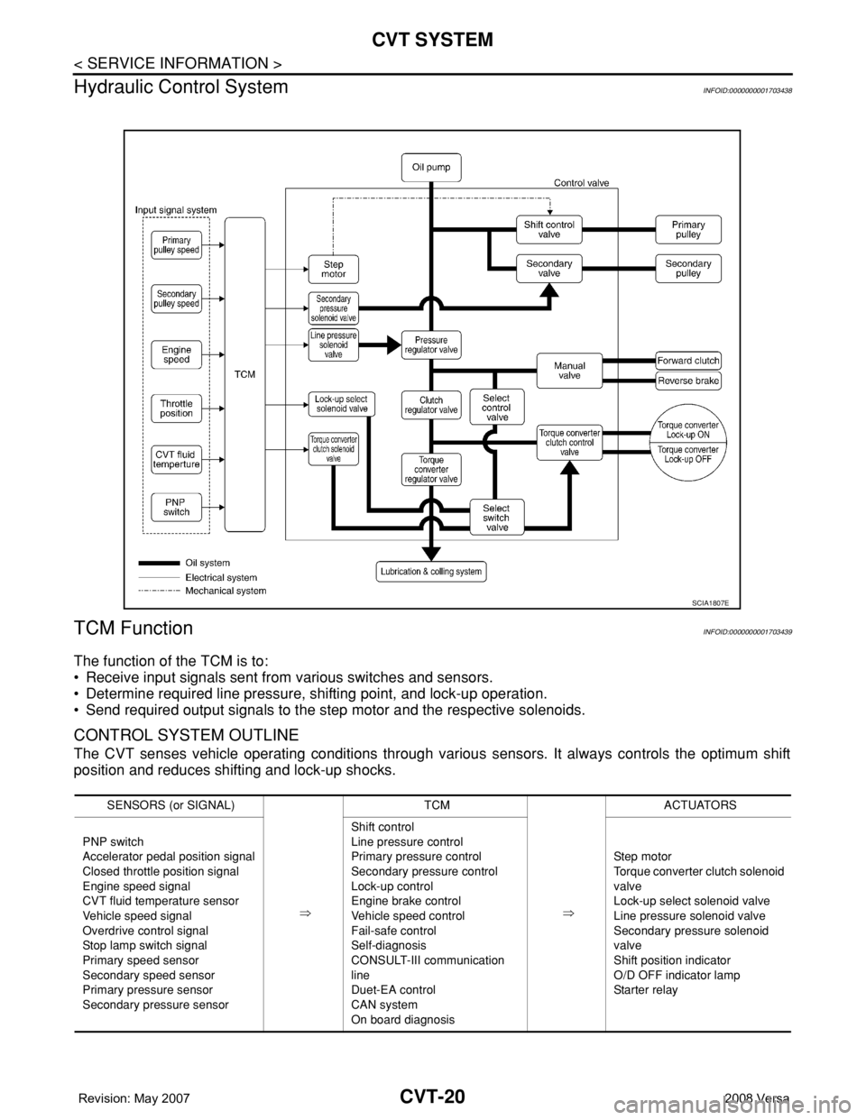
Hydraulic Control System
INFOID:0000000001703438
TCM FunctionINFOID:0000000001703439
The function of the TCM is to:
• Receive input signals sent from various switches and sensors.
• Determine required line pressure, shifting point, and lock-up operation.
• Send required output signals to the step motor and the respective solenoids.
CONTROL SYSTEM OUTLINE
The CVT senses vehicle operating conditions through various sensors. It always controls the optimum shift
position and reduces shifting and lock-up shocks.
SCIA1807E
SENSORS (or SIGNAL)
⇒TCM
⇒ACTUATORS
PNP switch
Accelerator pedal position signal
Closed throttle position signal
Engine speed signal
CVT fluid temperature sensor
Vehicle speed signal
Overdrive control signal
Stop lamp switch signal
Primary speed sensor
Secondary speed sensor
Primary pressure sensor
Secondary pressure sensorShift control
Line pressure control
Primary pressure control
Secondary pressure control
Lock-up control
Engine brake control
Vehicle speed control
Fail-safe control
Self-diagnosis
CONSULT-III communication
line
Duet-EA control
CAN system
On board diagnosisSte p m ot or
Torque converter clutch solenoid
valve
Lock-up select solenoid valve
Line pressure solenoid valve
Secondary pressure solenoid
valve
Shift position indicator
O/D OFF indicator lamp
Starter relay
Page 861 of 2771

CVT-22
< SERVICE INFORMATION >
CVT SYSTEM
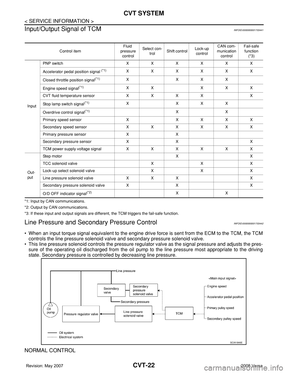
Input/Output Signal of TCM
INFOID:0000000001703441
*1: Input by CAN communications.
*2: Output by CAN communications.
*3: If these input and output signals are different, the TCM triggers the fail-safe function.
Line Pressure and Secondary Pressure ControlINFOID:0000000001703442
• When an input torque signal equivalent to the engine drive force is sent from the ECM to the TCM, the TCM
controls the line pressure solenoid valve and secondary pressure solenoid valve.
• This line pressure solenoid controls the pressure regulator valve as the signal pressure and adjusts the pres-
sure of the operating oil discharged from the oil pump to the line pressure most appropriate to the driving
state. Secondary pressure is controlled by decreasing line pressure.
NORMAL CONTROL
Control itemFluid
pressure
controlSelect con-
trolShift controlLock-up
controlCAN com-
munication
controlFail-safe
function
(*3)
InputPNP switch XXXXXX
Accelerator pedal position signal
(*1)XXXXXX
Closed throttle position signal
(*1)X XXX
Engine speed signal
(*1)XX XXX
CVT fluid temperature sensor X X X X X
Stop lamp switch signal
(*1)X XXX
Overdrive control signal
(*1)XX
Primary speed sensor X X X X X
Secondary speed sensor X X X X X X
Primary pressure sensor X X
Secondary pressure sensor X X X
TCM power supply voltage signal X X X X X X
Out-
putStep motor X X
TCC solenoid valve X X X
Lock-up select solenoid valve X X X
Line pressure solenoid valve X X X X
Secondary pressure solenoid valve X X X
O/D OFF indicator signal
(*2)XX
SCIA1846E