2008 NISSAN LATIO ECO mode
[x] Cancel search: ECO modePage 1158 of 2771
EC-84
< SERVICE INFORMATION >
TROUBLE DIAGNOSIS
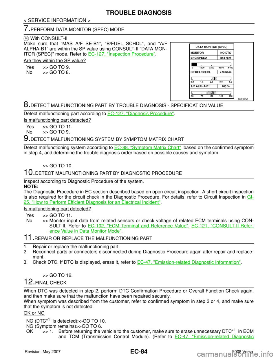
7.PERFORM DATA MONITOR (SPEC) MODE
With CONSULT-II
Make sure that “MAS A/F SE-B1”, “B/FUEL SCHDL”, and “A/F
ALPHA-B1” are within the SP value using CONSULT-II “DATA MON-
ITOR (SPEC)” mode. Refer to EC-127, "
Inspection Procedure".
Are they within the SP value?
Ye s > > G O T O 9 .
No >> GO TO 8.
8.DETECT MALFUNCTIONING PART BY TROUBLE DIAGNOSIS - SPECIFICATION VALUE
Detect malfunctioning part according to EC-127, "
Diagnosis Procedure".
Is malfunctioning part detected?
Ye s > > G O T O 11 .
No >> GO TO 9.
9.DETECT MALFUNCTIONING SYSTEM BY SYMPTOM MATRIX CHART
Detect malfunctioning system according to EC-88, "
Symptom Matrix Chart" based on the confirmed symptom
in step 4, and determine the trouble diagnosis order based on possible causes and symptom.
>> GO TO 10.
10.DETECT MALFUNCTIONING PART BY DIAGNOSTIC PROCEDURE
Inspect according to Diagnostic Procedure of the system.
NOTE:
The Diagnostic Procedure in EC section described based on open circuit inspection. A short circuit inspection
is also required for the circuit check in the Diagnostic Procedure. For details, refer to Circuit Inspection in GI-
25, "How to Perform Efficient Diagnosis for an Electrical Incident".
Is malfunctioning part detected?
Ye s > > G O T O 11 .
No >> Monitor input data from related sensors or check voltage of related ECM terminals using CON-
SULT-II. Refer to EC-102, "
ECM Terminal and Reference Value", EC-121, "CONSULT-II Refer-
ence Value in Data Monitor Mode".
11 .REPAIR OR REPLACE THE MALFUNCTIONING PART
1. Repair or replace the malfunctioning part.
2. Reconnect parts or connectors disconnected during Diagnostic Procedure again after repair and replace-
ment.
3. Check DTC. If DTC is displayed, erase it, refer to EC-47, "
Emission-related Diagnostic Information".
>> GO TO 12.
12.FINAL CHECK
When DTC was detected in step 2, perform DTC Confirmation Procedure or Overall Function Check again,
and then make sure that the malfunction have been repaired securely.
When symptom was described from the customer, refer to confirmed symptom in step 3 or 4, and make sure
that the symptom is not detected.
OK or NG
NG (DTC*1 is detected)>>GO TO 10.
NG (Symptom remains)>>GO TO 6.
OK >> 1. Before returning the vehicle to the customer, make sure to erase unnecessary DTC*
1 in ECM
and TCM (Transmission Control Module). (Refer to EC-47, "
Emission-related Diagnostic
SEF601Z
Page 1187 of 2771

TROUBLE DIAGNOSIS
EC-113
< SERVICE INFORMATION >
C
D
E
F
G
H
I
J
K
L
MA
EC
N
P O
*: The items are the same as those of 1st trip freeze frame data.
DATA MONITOR MODE
Monitored Item
×: Applicable
INT/A TEMP SE
[°C] or [°F]• The intake air temperature at the moment a malfunction is detected is displayed.
FUEL SYS-B2
• Always a certain value is displayed.
• These items can not efficiently for C11 models. L-FUEL TRM-B2 [%]
S-FUEL TRM-B2 [%]
INT MANI PRES [kPa]
FTFMCH1Freeze frame data
item*Description
Monitored item [Unit]ECM IN-
PUT SIG-
NALSMAIN
SIG-
NALSDescription Remarks
ENG SPEED [rpm]×ו Indicates the engine speed computed from the
signals of the crankshaft position sensor (POS)
and camshaft position sensor (PHASE).• Accuracy becomes poor if engine
speed drops below the idle rpm.
• If the signal is interrupted while
the engine is running, an abnor-
mal value may be indicated.
MAS A/F SE-B1 [V]×ו The signal voltage of the mass air flow sensor
is displayed.• When the engine is stopped, a
certain value is indicated.
B/FUEL SCHDL
[msec]ו “Base fuel schedule” indicates the fuel injection
pulse width programmed into ECM, prior to any
learned on board correction.
A/F ALPHA-B1 [%]ו The mean value of the air-fuel ratio feedback
correction factor per cycle is indicated.• When the engine is stopped, a
certain value is indicated.
• This data also includes the data
for the air/fuel ratio learning con-
trol.
COOLAN TEMP/S
[°C] or [°F]×ו The engine coolant temperature (determined
by the signal voltage of the engine coolant tem-
perature sensor) is displayed.• When the engine coolant temper-
ature sensor is open or short-cir-
cuited, ECM enters fail-safe
mode. The engine coolant tem-
perature determined by the ECM
is displayed.
A/F SEN1 (B1) [V]×ו The A/F signal computed from the input signal
of the A/F sensor 1 is displayed.
HO2S2 (B1) [V]ו The signal voltage of the heated oxygen sensor
2 is displayed.
HO2S2 MNTR (B1)
[RICH/LEAN]ו Display of heated oxygen sensor 2 signal:
RICH: means the amount of oxygen after three
way catalyst is relatively small.
LEAN: means the amount of oxygen after three
way catalyst is relatively large.• When the engine is stopped, a
certain value is indicated.
VHCL SPEED SE
[km/h] or [mph]×ו The vehicle speed computed from the vehicle
speed signal is displayed.
BATTERY VOLT [V]×ו The power supply voltage of ECM is displayed.
ACCEL SEN 1 [V]××
• The accelerator pedal position sensor signal
voltage is displayed.• ACCEL SEN 2 signal is converted
by ECM internally. Thus, it differs
from ECM terminal voltage signal. ACCEL SEN 2 [V]×
THRTL SEN 1 [V]××
• The throttle position sensor signal voltage is
displayed.• THRTL SEN 2 signal is converted
by ECM internally. Thus, it differs
from ECM terminal voltage signal. THRTL SEN 2 [V]×
Page 1192 of 2771
EC-118
< SERVICE INFORMATION >
TROUBLE DIAGNOSIS
*: Leaving cooling fan OFF with CONSULT-II while engine is running may cause the engine to overheat.
DTC & SRT CONFIRMATION MODE
SRT STATUS Mode
For details, refer to EC-47, "Emission-related Diagnostic Information".
SRT WORK SUPPORT Mode
This mode enables a technician to drive a vehicle to set the SRT while monitoring the SRT status.
DTC WORK SUPPORT Mode
*: DTC P1442 and P1456 does not apply to C11 models but appears in DTC Work Support Mode screens.
REAL TIME DIAGNOSIS IN DATA MONITOR MODE (RECORDING VEHICLE DATA)
Description
CONSULT-II has two kinds of triggers and they can be selected by touching “SETTING” in “DATA MONITOR”
mode.
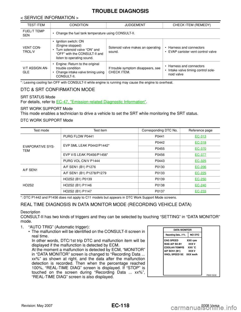
1. “AUTO TRIG” (Automatic trigger):
• The malfunction will be identified on the CONSULT-II screen in
real time.
In other words, DTC/1st trip DTC and malfunction item will be
displayed if the malfunction is detected by ECM.
At the moment a malfunction is detected by ECM, “MONITOR”
in “DATA MONITOR” screen is changed to “Recording Data ...
xx%” as shown at right, and the data after the malfunction
detection is recorded. Then when the percentage reached
100%, “REAL-TIME DIAG” screen is displayed. If “STOP” is
touched on the screen during “Recording Data ... xx%”,
“REAL-TIME DIAG” screen is also displayed.
FUEL/T TEMP
SEN• Change the fuel tank temperature using CONSULT-II.
VENT CON-
TROL/V•Ignition switch: ON
(Engine stopped)
• Turn solenoid valve “ON” and
“OFF” with the CONSULT-II and
listen to operating sound.Solenoid valve makes an operating
sound.• Harness and connectors
• EVAP canister vent control valve
V/T ASSIGN AN-
GLE• Engine: Return to the original
trouble condition
• Change intake valve timing using
CONSULT-II.If trouble symptom disappears, see
CHECK ITEM.• Harness and connectors
• Intake valve timing control sole-
noid valve TEST ITEM CONDITION JUDGEMENT CHECK ITEM (REMEDY)
Test mode Test item Corresponding DTC No. Reference page
EVAPORATIVE SYS-
TEMPURG FLOW P0441 P0441EC-313
EVP SML LEAK P0442/P1442*P0442EC-318P0455EC-370
EVP V/S LEAK P0456/P1456* P0456EC-377
PURG VOL CN/V P1444 P0443EC-325
A/F SEN1A/F SEN1 (B1) P1276 P0130EC-206A/F SEN1 (B1) P1278/P1279 P0133EC-225
HO2S2HO2S2 (B1) P0139 P0139EC-250HO2S2 (B1) P1146 P0138EC-240
HO2S2 (B1) P1147 P0137EC-233
PBIB1593E
Page 1193 of 2771
TROUBLE DIAGNOSIS
EC-119
< SERVICE INFORMATION >
C
D
E
F
G
H
I
J
K
L
MA
EC
N
P O
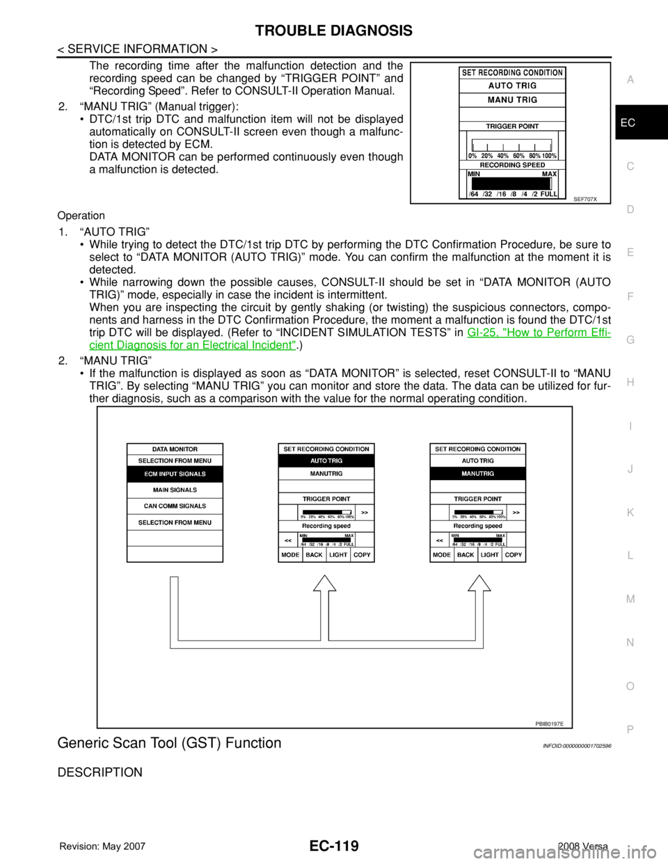
The recording time after the malfunction detection and the
recording speed can be changed by “TRIGGER POINT” and
“Recording Speed”. Refer to CONSULT-II Operation Manual.
2. “MANU TRIG” (Manual trigger):
• DTC/1st trip DTC and malfunction item will not be displayed
automatically on CONSULT-II screen even though a malfunc-
tion is detected by ECM.
DATA MONITOR can be performed continuously even though
a malfunction is detected.
Operation
1. “AUTO TRIG”
• While trying to detect the DTC/1st trip DTC by performing the DTC Confirmation Procedure, be sure to
select to “DATA MONITOR (AUTO TRIG)” mode. You can confirm the malfunction at the moment it is
detected.
• While narrowing down the possible causes, CONSULT-II should be set in “DATA MONITOR (AUTO
TRIG)” mode, especially in case the incident is intermittent.
When you are inspecting the circuit by gently shaking (or twisting) the suspicious connectors, compo-
nents and harness in the DTC Confirmation Procedure, the moment a malfunction is found the DTC/1st
trip DTC will be displayed. (Refer to “INCIDENT SIMULATION TESTS” in GI-25, "
How to Perform Effi-
cient Diagnosis for an Electrical Incident".)
2. “MANU TRIG”
• If the malfunction is displayed as soon as “DATA MONITOR” is selected, reset CONSULT-II to “MANU
TRIG”. By selecting “MANU TRIG” you can monitor and store the data. The data can be utilized for fur-
ther diagnosis, such as a comparison with the value for the normal operating condition.
Generic Scan Tool (GST) FunctionINFOID:0000000001702596
DESCRIPTION
SEF707X
PBIB0197E
Page 1206 of 2771
EC-132
< SERVICE INFORMATION >
TROUBLE DIAGNOSIS - SPECIFICATION VALUE
12.CHECK A/F SENSOR 1 FUNCTION
Perform all DTC Confirmation Procedure related with A/F sensor 1.
• For DTC P0130, refer to EC-206, "
DTC Confirmation Procedure".
• For DTC P0131, refer to EC-213, "
DTC Confirmation Procedure".
• For DTC P0132, refer to EC-219, "
DTC Confirmation Procedure".
• For DTC P0133, refer to EC-225, "
DTC Confirmation Procedure".
• For DTC P2A00, refer to EC-500, "
DTC Confirmation Procedure".
OK or NG
OK >> GO TO 15.
NG >> GO TO 13.
13.CHECK A/F SENSOR 1 CIRCUIT
Perform Diagnostic Procedure according to corresponding DTC.
>> GO TO 14.
14.CHECK “A/F ALPHA-B1”
1. Start engine.
2. Select “A/F ALPHA-B1” in “DATA MONITOR (SPEC)” mode, and make sure that the indication is within
the SP value.
OK or NG
OK >>INSPECTION END
NG >> GO TO 15.
15.DISCONNECT AND RECONNECT ECM HARNESS CONNECTOR
1. Stop the engine.
2. Disconnect ECM harness connector. Check pin terminal and connector for damage, and then reconnect it.
>> GO TO 16.
16.CHECK “A/F ALPHA-B1”
1. Start engine.
2. Select “A/F ALPHA-B1” in “DATA MONITOR (SPEC)” mode, and make sure that the indication is within
the SP value.
OK or NG
OK >>INSPECTION END
NG >> Detect malfunctioning part according to EC-88, "
Symptom Matrix Chart".
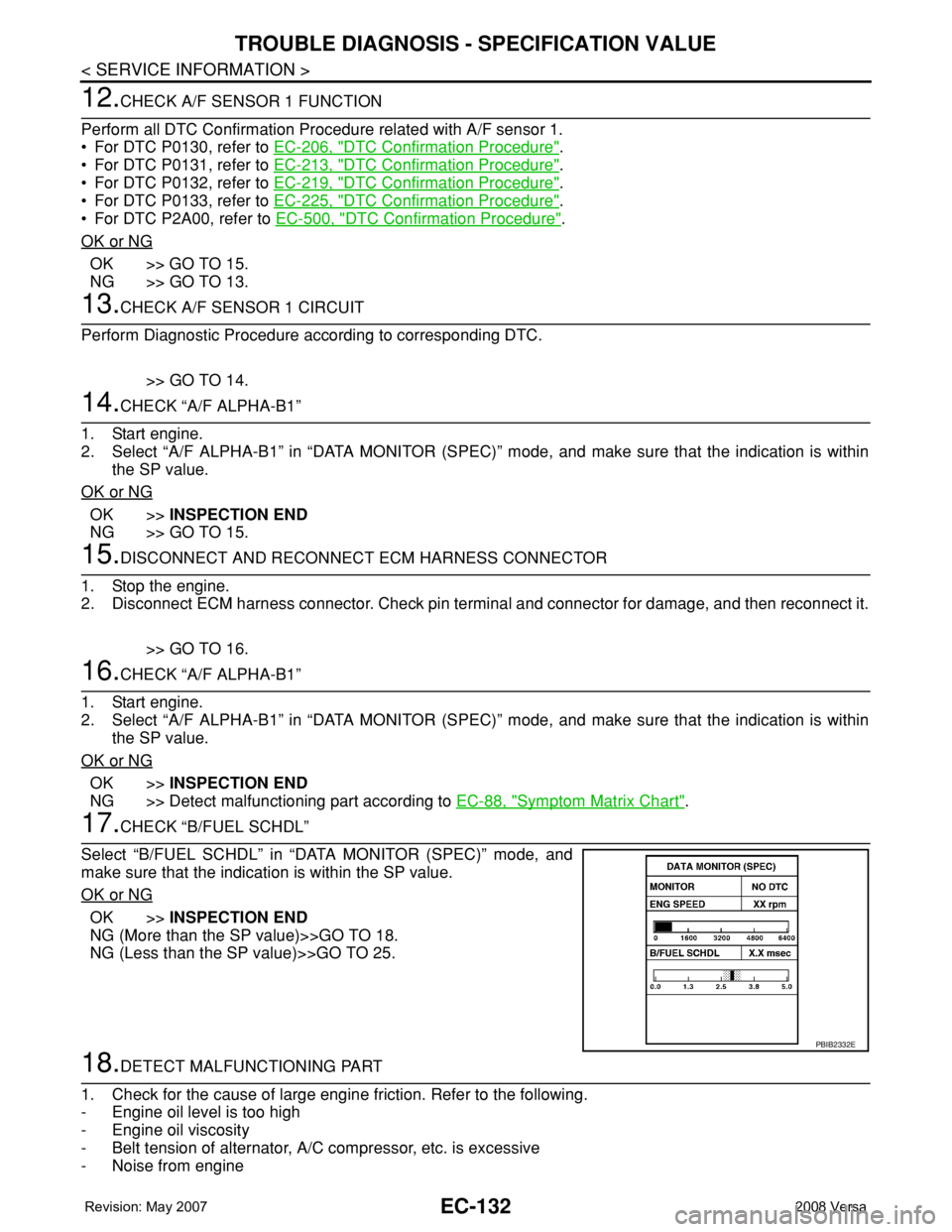
17.CHECK “B/FUEL SCHDL”
Select “B/FUEL SCHDL” in “DATA MONITOR (SPEC)” mode, and
make sure that the indication is within the SP value.
OK or NG
OK >>INSPECTION END
NG (More than the SP value)>>GO TO 18.
NG (Less than the SP value)>>GO TO 25.
18.DETECT MALFUNCTIONING PART
1. Check for the cause of large engine friction. Refer to the following.
- Engine oil level is too high
- Engine oil viscosity
- Belt tension of alternator, A/C compressor, etc. is excessive
- Noise from engine
PBIB2332E
Page 1207 of 2771
TROUBLE DIAGNOSIS - SPECIFICATION VALUE
EC-133
< SERVICE INFORMATION >
C
D
E
F
G
H
I
J
K
L
MA
EC
N
P O
- Noise from transmission, etc.
2. Check for the cause of insufficient combustion. Refer to the following.
- Valve clearance malfunction
- Intake valve timing control function malfunction
- Camshaft sprocket installation malfunction, etc.
>> Repair or replace malfunctioning part, and then GO TO 30.
19.CHECK INTAKE SYSTEM
Check for the cause of uneven air flow through mass air flow sensor. Refer to the following.
• Crushed air ducts
• Malfunctioning seal of air cleaner element
• Uneven dirt of air cleaner element
• Improper specification of intake air system
OK or NG
OK >> GO TO 21.
NG >> Repair or replace malfunctioning part, and then GO TO 20.
20.CHECK “A/F ALPHA-B1” AND “B/FUEL SCHDL”
Select “A/F ALPHA-B1” and “B/FUEL SCHDL” in “DATA MONITOR (SPEC)” mode, and make sure that the
each indication is within the SP value.
OK or NG
OK >>INSPECTION END
NG (“B/FUEL SCHDL” is more, “A/F ALPHA-B1” is less than the SP value)>>GO TO 21.
21.DISCONNECT AND RECONNECT MASS AIR FLOW SENSOR HARNESS CONNECTOR
1. Stop the engine.
2. Disconnect mass air flow sensor harness connector. Check pin terminal and connector for damage and
then reconnect it again.
>> GO TO 22.
22.CHECK “A/F ALPHA-B1”
1. Start engine.
2. Select “A/F ALPHA-B1” in “DATA MONITOR (SPEC)” mode, and make sure that the indication is within
the SP value.
OK or NG
OK >> 1. Detect malfunctioning part of mass air flow sensor circuit and repair it. Refer to EC-167.
2. GO TO 29.
NG >> GO TO 23.
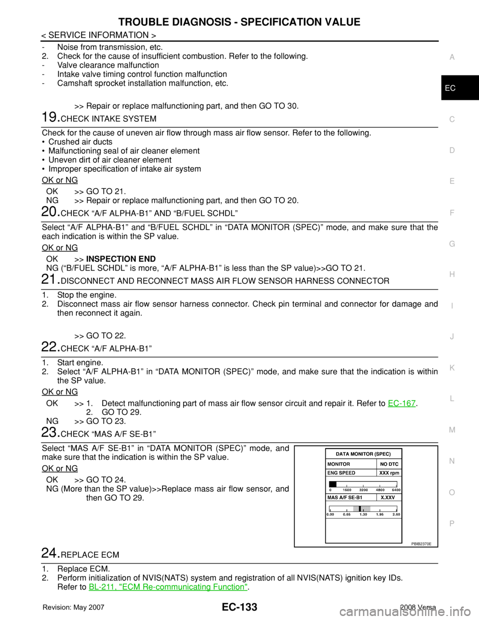
23.CHECK “MAS A/F SE-B1”
Select “MAS A/F SE-B1” in “DATA MONITOR (SPEC)” mode, and
make sure that the indication is within the SP value.
OK or NG
OK >> GO TO 24.
NG (More than the SP value)>>Replace mass air flow sensor, and
then GO TO 29.
24.REPLACE ECM
1. Replace ECM.
2. Perform initialization of NVIS(NATS) system and registration of all NVIS(NATS) ignition key IDs.
Refer to BL-211, "
ECM Re-communicating Function".
PBIB2370E
Page 1217 of 2771

DTC U1000, U1001 CAN COMMUNICATION LINE
EC-143
< SERVICE INFORMATION >
C
D
E
F
G
H
I
J
K
L
MA
EC
N
P O
DTC U1000, U1001 CAN COMMUNICATION LINE
DescriptionINFOID:0000000001702608
CAN (Controller Area Network) is a serial communication line for real time application. It is an on-vehicle mul-
tiplex communication line with high data communication speed and excellent error detection ability. Many elec-
tronic control units are equipped onto a vehicle, and each control unit shares information and links with other
control units during operation (not independent). In CAN communication, control units are connected with 2
communication lines (CAN H line, CAN L line) allowing a high rate of information transmission with less wiring.
Each control unit transmits/receives data but selectively reads required data only.
On Board Diagnosis LogicINFOID:0000000001702609
*1: This self-diagnosis has the one trip detection logic (A/T, CVT).
The MIL will not light up for this self-diagnosis (M/T).
*2: The MIL will not light up for this self-diagnosis.
DTC Confirmation ProcedureINFOID:0000000001702610
1. Turn ignition switch ON and wait at least 3 seconds.
2. Select “DATA MONITOR” mode with CONSULT-II.
3. If 1st trip DTC is detected, go to EC-144, "
Diagnosis Procedure".
DTC No.Trouble diagnosis
nameDTC detecting condition Possible cause
U1000*
1
1000*1CAN communication
lineWhen ECM is not transmitting or receiving CAN
communication signal of OBD (emission related
diagnosis) for 2 seconds or more.• Harness or connectors
(CAN communication line is open or
shorted.)
U1001*
2
1001*2
When ECM is not transmitting or receiving CAN
communication signal other than OBD (emission-
related diagnosis) for 2 seconds or more.
Page 1222 of 2771
EC-148
< SERVICE INFORMATION >
DTC P0011 IVT CONTROL
On Board Diagnosis Logic
INFOID:0000000001702619
FAIL-SAFE MODE
ECM enters in fail-safe mode when the malfunction is detected.
DTC Confirmation ProcedureINFOID:0000000001702620
CAUTION:
Always drive at a safe speed.
NOTE:
•If DTC P0011 is displayed with DTC P0075, first perform trouble diagnosis for DTC P0075.
See EC-162
.
• If DTC Confirmation Procedure has been previously conducted, always turn ignition switch OFF and wait at
least 10 seconds before conducting the next test.
TESTING CONDITION:
Before performing the following procedure, confirm that battery voltage is between 10V and 16V at
idle.
WITH CONSULT-II
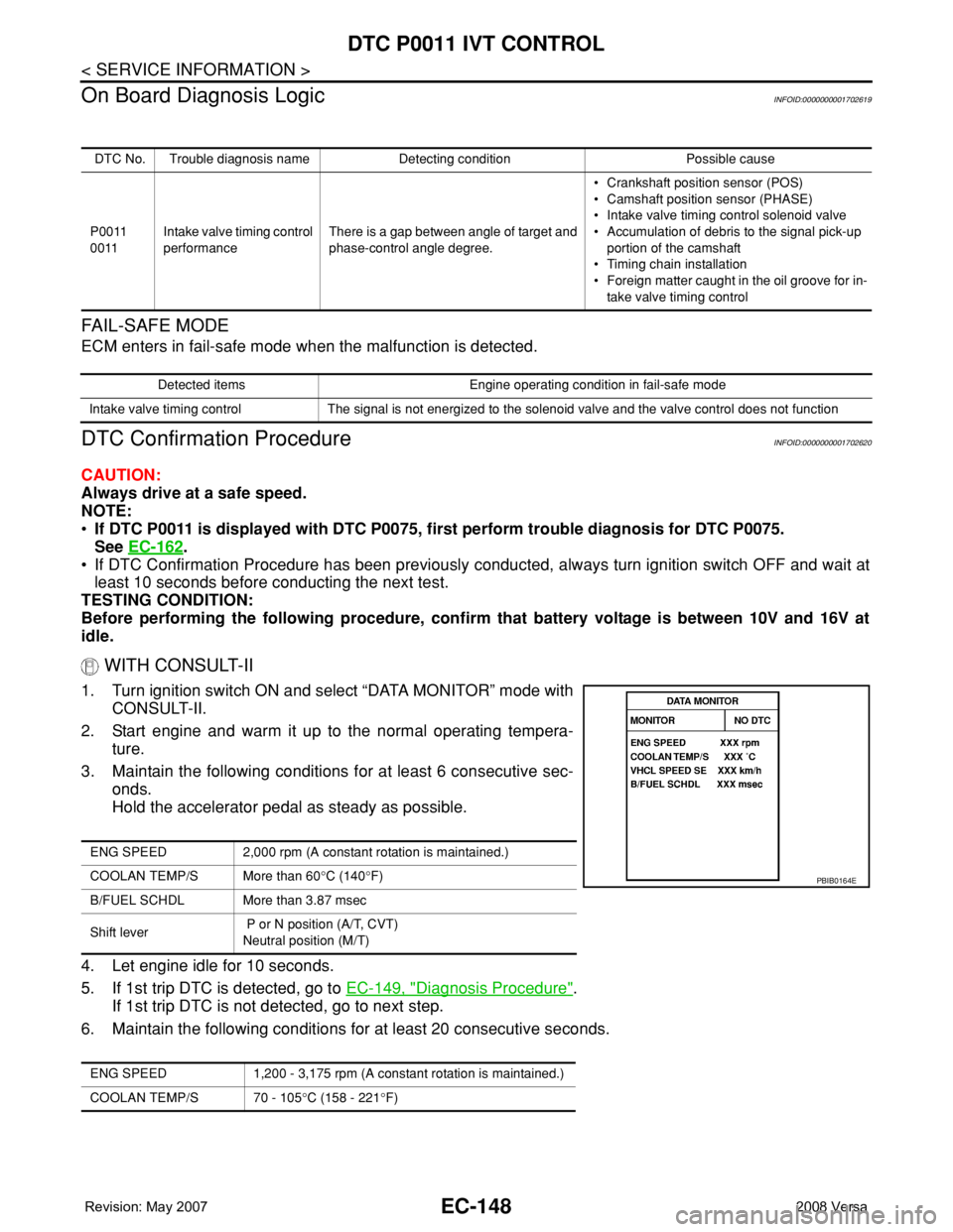
1. Turn ignition switch ON and select “DATA MONITOR” mode with
CONSULT-II.
2. Start engine and warm it up to the normal operating tempera-
ture.
3. Maintain the following conditions for at least 6 consecutive sec-
onds.
Hold the accelerator pedal as steady as possible.
4. Let engine idle for 10 seconds.
5. If 1st trip DTC is detected, go to EC-149, "
Diagnosis Procedure".
If 1st trip DTC is not detected, go to next step.
6. Maintain the following conditions for at least 20 consecutive seconds.
DTC No. Trouble diagnosis name Detecting condition Possible cause
P0011
0011Intake valve timing control
performanceThere is a gap between angle of target and
phase-control angle degree.• Crankshaft position sensor (POS)
• Camshaft position sensor (PHASE)
• Intake valve timing control solenoid valve
• Accumulation of debris to the signal pick-up
portion of the camshaft
• Timing chain installation
• Foreign matter caught in the oil groove for in-
take valve timing control
Detected items Engine operating condition in fail-safe mode
Intake valve timing control The signal is not energized to the solenoid valve and the valve control does not function
ENG SPEED 2,000 rpm (A constant rotation is maintained.)
COOLAN TEMP/S More than 60°C (140°F)
B/FUEL SCHDL More than 3.87 msec
Shift lever P or N position (A/T, CVT)
Neutral position (M/T)
ENG SPEED 1,200 - 3,175 rpm (A constant rotation is maintained.)
COOLAN TEMP/S 70 - 105°C (158 - 221°F)
PBIB0164E