2008 NISSAN LATIO ECO mode
[x] Cancel search: ECO modePage 975 of 2771
CVT-136
< SERVICE INFORMATION >
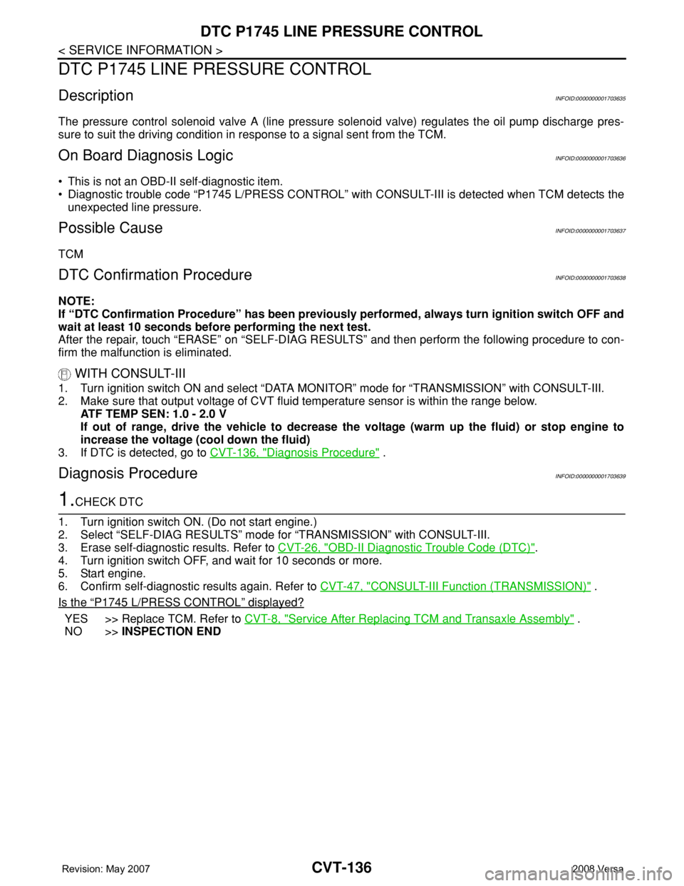
DTC P1745 LINE PRESSURE CONTROL
DTC P1745 LINE PRESSURE CONTROL
DescriptionINFOID:0000000001703635
The pressure control solenoid valve A (line pressure solenoid valve) regulates the oil pump discharge pres-
sure to suit the driving condition in response to a signal sent from the TCM.
On Board Diagnosis LogicINFOID:0000000001703636
• This is not an OBD-II self-diagnostic item.
• Diagnostic trouble code “P1745 L/PRESS CONTROL” with CONSULT-III is detected when TCM detects the
unexpected line pressure.
Possible CauseINFOID:0000000001703637
TCM
DTC Confirmation ProcedureINFOID:0000000001703638
NOTE:
If “DTC Confirmation Procedure” has been previously performed, always turn ignition switch OFF and
wait at least 10 seconds before performing the next test.
After the repair, touch “ERASE” on “SELF-DIAG RESULTS” and then perform the following procedure to con-
firm the malfunction is eliminated.
WITH CONSULT-III
1. Turn ignition switch ON and select “DATA MONITOR” mode for “TRANSMISSION” with CONSULT-III.
2. Make sure that output voltage of CVT fluid temperature sensor is within the range below.
ATF TEMP SEN: 1.0 - 2.0 V
If out of range, drive the vehicle to decrease the voltage (warm up the fluid) or stop engine to
increase the voltage (cool down the fluid)
3. If DTC is detected, go to CVT-136, "
Diagnosis Procedure" .
Diagnosis ProcedureINFOID:0000000001703639
1.CHECK DTC
1. Turn ignition switch ON. (Do not start engine.)
2. Select “SELF-DIAG RESULTS” mode for “TRANSMISSION” with CONSULT-III.
3. Erase self-diagnostic results. Refer to CVT-26, "
OBD-II Diagnostic Trouble Code (DTC)".
4. Turn ignition switch OFF, and wait for 10 seconds or more.
5. Start engine.
6. Confirm self-diagnostic results again. Refer to CVT-47, "
CONSULT-III Function (TRANSMISSION)" .
Is the
“P1745 L/PRESS CONTROL” displayed?
YES >> Replace TCM. Refer to CVT-8, "Service After Replacing TCM and Transaxle Assembly" .
NO >>INSPECTION END
Page 976 of 2771
DTC P1777 STEP MOTOR - CIRCUIT
CVT-137
< SERVICE INFORMATION >
D
E
F
G
H
I
J
K
L
MA
B
CVT
N
O
P
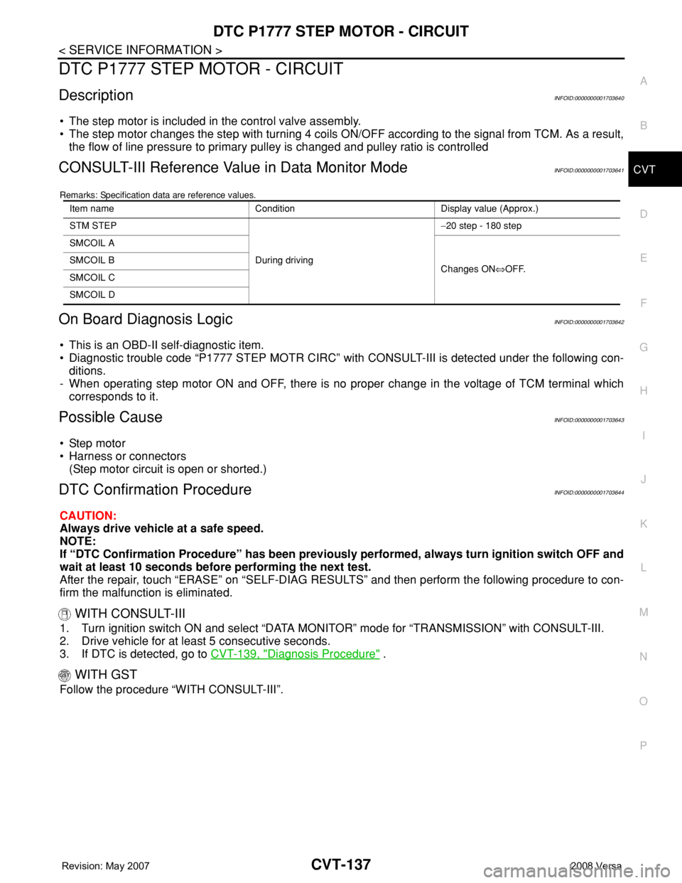
DTC P1777 STEP MOTOR - CIRCUIT
DescriptionINFOID:0000000001703640
• The step motor is included in the control valve assembly.
• The step motor changes the step with turning 4 coils ON/OFF according to the signal from TCM. As a result,
the flow of line pressure to primary pulley is changed and pulley ratio is controlled
CONSULT-III Reference Value in Data Monitor ModeINFOID:0000000001703641
Remarks: Specification data are reference values.
On Board Diagnosis LogicINFOID:0000000001703642
• This is an OBD-II self-diagnostic item.
• Diagnostic trouble code “P1777 STEP MOTR CIRC” with CONSULT-III is detected under the following con-
ditions.
- When operating step motor ON and OFF, there is no proper change in the voltage of TCM terminal which
corresponds to it.
Possible CauseINFOID:0000000001703643
• Step motor
• Harness or connectors
(Step motor circuit is open or shorted.)
DTC Confirmation ProcedureINFOID:0000000001703644
CAUTION:
Always drive vehicle at a safe speed.
NOTE:
If “DTC Confirmation Procedure” has been previously performed, always turn ignition switch OFF and
wait at least 10 seconds before performing the next test.
After the repair, touch “ERASE” on “SELF-DIAG RESULTS” and then perform the following procedure to con-
firm the malfunction is eliminated.
WITH CONSULT-III
1. Turn ignition switch ON and select “DATA MONITOR” mode for “TRANSMISSION” with CONSULT-III.
2. Drive vehicle for at least 5 consecutive seconds.
3. If DTC is detected, go to CVT-139, "
Diagnosis Procedure" .
WITH GST
Follow the procedure “WITH CONSULT-III”.
Item name Condition Display value (Approx.)
STM STEP
During driving−20 step - 180 step
SMCOIL A
Changes ON⇔OFF. SMCOIL B
SMCOIL C
SMCOIL D
Page 980 of 2771
DTC P1778 STEP MOTOR - FUNCTION
CVT-141
< SERVICE INFORMATION >
D
E
F
G
H
I
J
K
L
MA
B
CVT
N
O
P
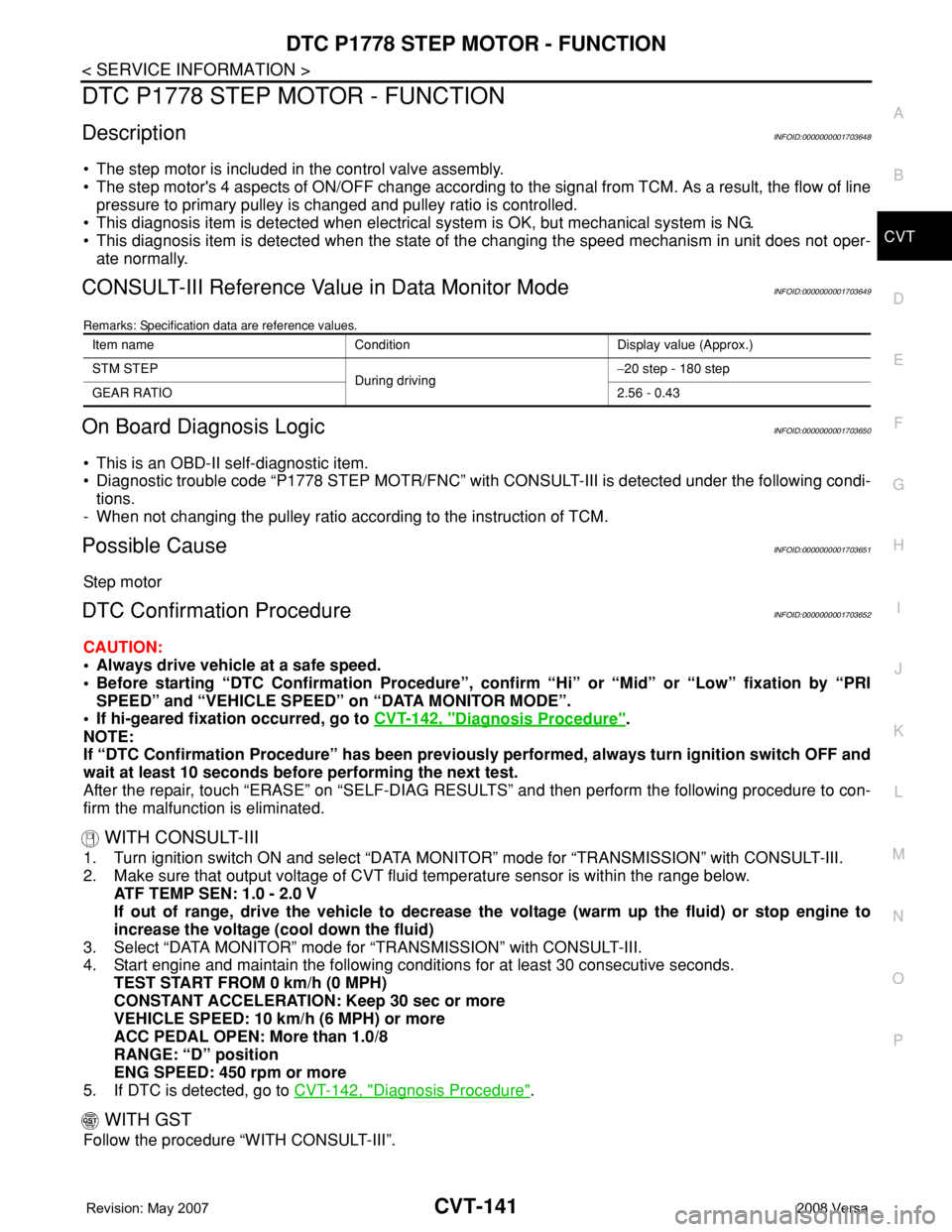
DTC P1778 STEP MOTOR - FUNCTION
DescriptionINFOID:0000000001703648
• The step motor is included in the control valve assembly.
• The step motor's 4 aspects of ON/OFF change according to the signal from TCM. As a result, the flow of line
pressure to primary pulley is changed and pulley ratio is controlled.
• This diagnosis item is detected when electrical system is OK, but mechanical system is NG.
• This diagnosis item is detected when the state of the changing the speed mechanism in unit does not oper-
ate normally.
CONSULT-III Reference Value in Data Monitor ModeINFOID:0000000001703649
Remarks: Specification data are reference values.
On Board Diagnosis LogicINFOID:0000000001703650
• This is an OBD-II self-diagnostic item.
• Diagnostic trouble code “P1778 STEP MOTR/FNC” with CONSULT-III is detected under the following condi-
tions.
- When not changing the pulley ratio according to the instruction of TCM.
Possible CauseINFOID:0000000001703651
Step motor
DTC Confirmation ProcedureINFOID:0000000001703652
CAUTION:
• Always drive vehicle at a safe speed.
• Before starting “DTC Confirmation Procedure”, confirm “Hi” or “Mid” or “Low” fixation by “PRI
SPEED” and “VEHICLE SPEED” on “DATA MONITOR MODE”.
• If hi-geared fixation occurred, go to CVT-142, "
Diagnosis Procedure".
NOTE:
If “DTC Confirmation Procedure” has been previously performed, always turn ignition switch OFF and
wait at least 10 seconds before performing the next test.
After the repair, touch “ERASE” on “SELF-DIAG RESULTS” and then perform the following procedure to con-
firm the malfunction is eliminated.
WITH CONSULT-III
1. Turn ignition switch ON and select “DATA MONITOR” mode for “TRANSMISSION” with CONSULT-III.
2. Make sure that output voltage of CVT fluid temperature sensor is within the range below.
ATF TEMP SEN: 1.0 - 2.0 V
If out of range, drive the vehicle to decrease the voltage (warm up the fluid) or stop engine to
increase the voltage (cool down the fluid)
3. Select “DATA MONITOR” mode for “TRANSMISSION” with CONSULT-III.
4. Start engine and maintain the following conditions for at least 30 consecutive seconds.
TEST START FROM 0 km/h (0 MPH)
CONSTANT ACCELERATION: Keep 30 sec or more
VEHICLE SPEED: 10 km/h (6 MPH) or more
ACC PEDAL OPEN: More than 1.0/8
RANGE: “D” position
ENG SPEED: 450 rpm or more
5. If DTC is detected, go to CVT-142, "
Diagnosis Procedure".
WITH GST
Follow the procedure “WITH CONSULT-III”.
Item name Condition Display value (Approx.)
STM STEP
During driving−20 step - 180 step
GEAR RATIO2.56 - 0.43
Page 1020 of 2771
SERVICE DATA AND SPECIFICATIONS (SDS)
CVT-181
< SERVICE INFORMATION >
D
E
F
G
H
I
J
K
L
MA
B
CVT
N
O
P
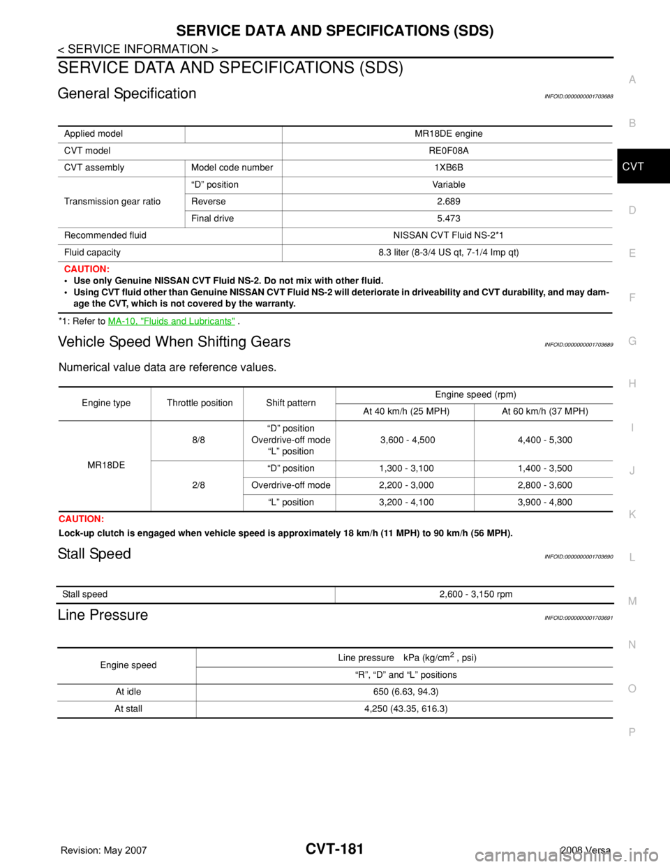
SERVICE DATA AND SPECIFICATIONS (SDS)
General SpecificationINFOID:0000000001703688
*1: Refer to MA-10, "Fluids and Lubricants" .
Vehicle Speed When Shifting GearsINFOID:0000000001703689
Numerical value data are reference values.
CAUTION:
Lock-up clutch is engaged when vehicle speed is approximately 18 km/h (11 MPH) to 90 km/h (56 MPH).
Stall SpeedINFOID:0000000001703690
Line PressureINFOID:0000000001703691
Applied model MR18DE engine
CVT modelRE0F08A
CVT assembly Model code number 1XB6B
Transmission gear ratio“D” position Variable
Reverse 2.689
Final drive 5.473
Recommended fluid NISSAN CVT Fluid NS-2*1
Fluid capacity 8.3 liter (8-3/4 US qt, 7-1/4 Imp qt)
CAUTION:
• Use only Genuine NISSAN CVT Fluid NS-2. Do not mix with other fluid.
• Using CVT fluid other than Genuine NISSAN CVT Fluid NS-2 will deteriorate in driveability and CVT durability, and may dam-
age the CVT, which is not covered by the warranty.
Engine type Throttle position Shift patternEngine speed (rpm)
At 40 km/h (25 MPH) At 60 km/h (37 MPH)
MR18DE8/8“D” position
Overdrive-off mode
“L” position 3,600 - 4,500 4,400 - 5,300
2/8“D” position 1,300 - 3,100 1,400 - 3,500
Overdrive-off mode 2,200 - 3,000 2,800 - 3,600
“L” position 3,200 - 4,100 3,900 - 4,800
Stall speed 2,600 - 3,150 rpm
Engine speed Line pressure kPa (kg/cm
2 , psi)
“R”, “D” and “L” positions
At idle 650 (6.63, 94.3)
At stall 4,250 (43.35, 616.3)
Page 1034 of 2771
COMBINATION METERS
DI-13
< SERVICE INFORMATION >
C
D
E
F
G
H
I
J
L
MA
B
DI
N
O
P
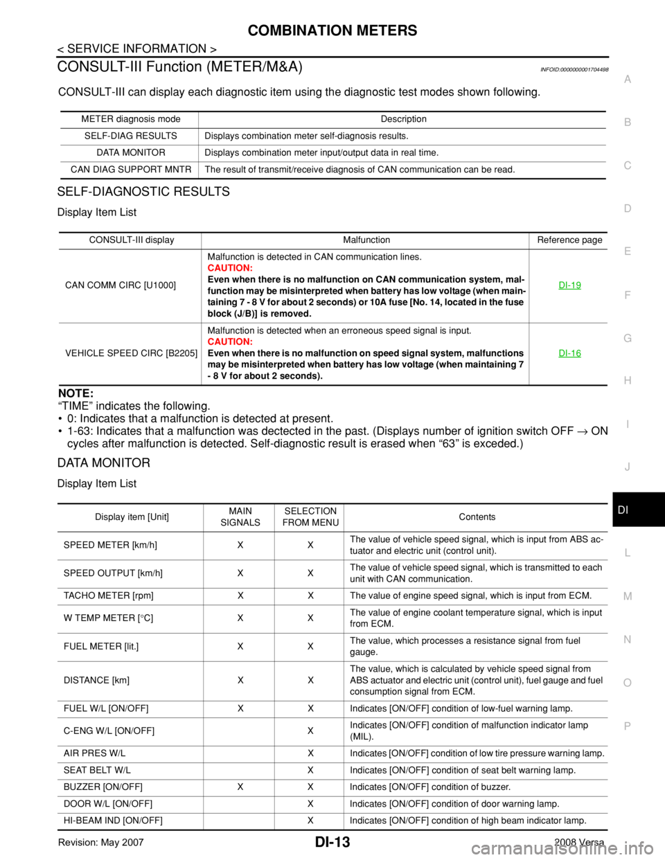
CONSULT-III Function (METER/M&A)INFOID:0000000001704498
CONSULT-III can display each diagnostic item using the diagnostic test modes shown following.
SELF-DIAGNOSTIC RESULTS
Display Item List
NOTE:
“TIME” indicates the following.
• 0: Indicates that a malfunction is detected at present.
• 1-63: Indicates that a malfunction was dectected in the past. (Displays number of ignition switch OFF → ON
cycles after malfunction is detected. Self-diagnostic result is erased when “63” is exceded.)
DATA MONITOR
Display Item List
METER diagnosis mode Description
SELF-DIAG RESULTS Displays combination meter self-diagnosis results.
DATA MONITOR Displays combination meter input/output data in real time.
CAN DIAG SUPPORT MNTR The result of transmit/receive diagnosis of CAN communication can be read.
CONSULT-III display Malfunction Reference page
CAN COMM CIRC [U1000]Malfunction is detected in CAN communication lines.
CAUTION:
Even when there is no malfunction on CAN communication system, mal-
function may be misinterpreted when battery has low voltage (when main-
taining 7 - 8 V for about 2 seconds) or 10A fuse [No. 14, located in the fuse
block (J/B)] is removed.DI-19
VEHICLE SPEED CIRC [B2205]Malfunction is detected when an erroneous speed signal is input.
CAUTION:
Even when there is no malfunction on speed signal system, malfunctions
may be misinterpreted when battery has low voltage (when maintaining 7
- 8 V for about 2 seconds).DI-16
Display item [Unit]MAIN
SIGNALSSELECTION
FROM MENUContents
SPEED METER [km/h] X XThe value of vehicle speed signal, which is input from ABS ac-
tuator and electric unit (control unit).
SPEED OUTPUT [km/h] X XThe value of vehicle speed signal, which is transmitted to each
unit with CAN communication.
TACHO METER [rpm] X X The value of engine speed signal, which is input from ECM.
W TEMP METER [°C] X XThe value of engine coolant temperature signal, which is input
from ECM.
FUEL METER [lit.] X XThe value, which processes a resistance signal from fuel
gauge.
DISTANCE [km] X XThe value, which is calculated by vehicle speed signal from
ABS actuator and electric unit (control unit), fuel gauge and fuel
consumption signal from ECM.
FUEL W/L [ON/OFF] X X Indicates [ON/OFF] condition of low-fuel warning lamp.
C-ENG W/L [ON/OFF] XIndicates [ON/OFF] condition of malfunction indicator lamp
(MIL).
AIR PRES W/L X Indicates [ON/OFF] condition of low tire pressure warning lamp.
SEAT BELT W/L X Indicates [ON/OFF] condition of seat belt warning lamp.
BUZZER [ON/OFF] X X Indicates [ON/OFF] condition of buzzer.
DOOR W/L [ON/OFF] X Indicates [ON/OFF] condition of door warning lamp.
HI-BEAM IND [ON/OFF] X Indicates [ON/OFF] condition of high beam indicator lamp.
Page 1115 of 2771
ON BOARD REFUELING VAPOR RECOVERY (ORVR)
EC-41
< SERVICE INFORMATION >
C
D
E
F
G
H
I
J
K
L
MA
EC
N
P O
1. Remove fuel tank. Refer to FL-9.
2. Drain fuel from the tank as follows:
a. Remove fuel feed hose located on the fuel gauge retainer.
b. Connect a spare fuel hose, one side to fuel gauge retainer where the hose was removed and the other
side to a fuel container.
c. Drain fuel using “FUEL PUMP RELAY” in “ACTIVE TEST” mode with CONSULT-II.
3. Check refueling EVAP vapor cut valve for being stuck to close as follows.
Blow air into the refueling EVAP vapor cut valve (from the end of EVAP/ORVR line hose), and check that
the air flows freely into the tank.
4. Check refueling EVAP vapor cut valve for being stuck to open as follows.
a. Connect vacuum pump to hose end.
b. Remove fuel gauge retainer with fuel gauge unit.
Always replace O-ring with new one.
c. Put fuel tank upside down.
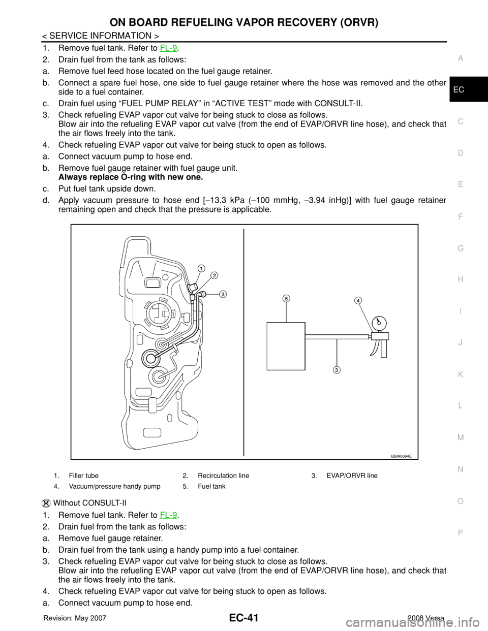
d. Apply vacuum pressure to hose end [−13.3 kPa (−100 mmHg, −3.94 inHg)] with fuel gauge retainer
remaining open and check that the pressure is applicable.
Without CONSULT-II
1. Remove fuel tank. Refer to FL-9.
2. Drain fuel from the tank as follows:
a. Remove fuel gauge retainer.
b. Drain fuel from the tank using a handy pump into a fuel container.
3. Check refueling EVAP vapor cut valve for being stuck to close as follows.
Blow air into the refueling EVAP vapor cut valve (from the end of EVAP/ORVR line hose), and check that
the air flows freely into the tank.
4. Check refueling EVAP vapor cut valve for being stuck to open as follows.
a. Connect vacuum pump to hose end.
1. Filler tube 2. Recirculation line 3. EVAP/ORVR line
4. Vacuum/pressure handy pump 5. Fuel tank
BBIA0694E
Page 1120 of 2771

EC-46
< SERVICE INFORMATION >
ON BOARD DIAGNOSTIC (OBD) SYSTEM
ON BOARD DIAGNOSTIC (OBD) SYSTEM
IntroductionINFOID:0000000001702573
The ECM has an on board diagnostic system, which detects malfunctions related to engine sensors or actua-
tors. The ECM also records various emission-related diagnostic information including:
The above information can be checked using procedures listed in the table below.
×: Applicable —: Not applicable
*: When DTC and 1st trip DTC simultaneously appear on the display, they cannot be clearly distinguished from each other.
The malfunction indicator lamp (MIL) on the instrument panel lights up when the same malfunction is detected
in two consecutive trips (Two trip detection logic), or when the ECM enters fail-safe mode.
(Refer to EC-87, "
Fail-Safe Chart".)
Two Trip Detection LogicINFOID:0000000001702574
When a malfunction is detected for the first time, 1st trip DTC and 1st trip Freeze Frame data are stored in the
ECM memory. The MIL will not light up at this stage. <1st trip>
If the same malfunction is detected again during the next drive, the DTC and Freeze Frame data are stored in
the ECM memory, and the MIL lights up. The MIL lights up at the same time when the DTC is stored. <2nd
trip> The “trip” in the “Two Trip Detection Logic” means a driving mode in which self-diagnosis is performed
during vehicle operation. Specific on board diagnostic items will cause the ECM to light up or blink the MIL,
and store DTC and Freeze Frame data, even in the 1st trip, as shown below.
×: Applicable —: Not applicable
When there is an open circuit on MIL circuit, the ECM cannot warn the driver by MIL lighting up when there is
malfunction on engine control system.
Emission-related diagnostic information Diagnostic service
Diagnostic Trouble Code (DTC) Service $03 of SAE J1979
Freeze Frame data Service $02 of SAE J1979
System Readiness Test (SRT) code Service $01 of SAE J1979
1st Trip Diagnostic Trouble Code (1st Trip DTC) Service $07 of SAE J1979
1st Trip Freeze Frame data
Test values and Test limits Service $06 of SAE J1979
Calibration ID Service $09 of SAE J1979
DTC 1st trip DTCFreeze Frame
data1st trip Freeze
Frame dataSRT code SRT status Test value
CONSULT-II××××××—
GST×× ×—×××
ECM××*———×—
ItemsMIL DTC 1st trip DTC
1st trip 2nd trip
1st trip
displaying2nd trip
displaying1st trip
displaying2nd trip
display-
ing BlinkingLighting
upBlinkingLighting
up
Misfire (Possible three way catalyst
damage) — DTC: P0300 - P0304 is
being detected×———— —×—
Misfire (Possible three way catalyst
damage) — DTC: P0300 - P0304 is
being detected——×——×——
One trip detection diagnoses
(Refer to EC-47, "
Emission-related
Diagnostic Information".)—×——×———
Except above — — —×—××—
Page 1124 of 2771
EC-50
< SERVICE INFORMATION >
ON BOARD DIAGNOSTIC (OBD) SYSTEM
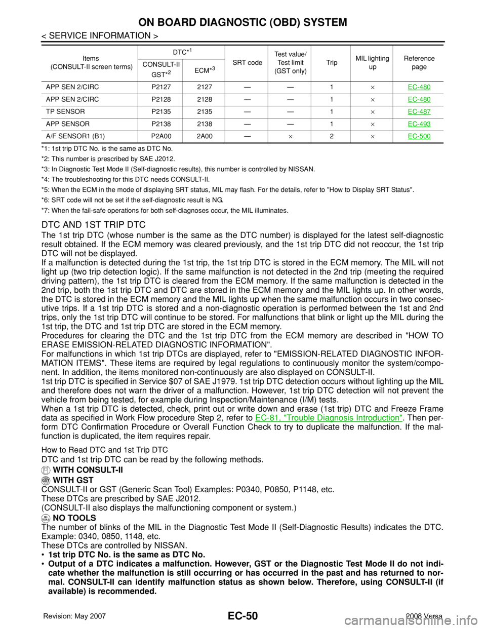
*1: 1st trip DTC No. is the same as DTC No.
*2: This number is prescribed by SAE J2012.
*3: In Diagnostic Test Mode II (Self-diagnostic results), this number is controlled by NISSAN.
*4: The troubleshooting for this DTC needs CONSULT-II.
*5: When the ECM in the mode of displaying SRT status, MIL may flash. For the details, refer to "How to Display SRT Status".
*6: SRT code will not be set if the self-diagnostic result is NG.
*7: When the fail-safe operations for both self-diagnoses occur, the MIL illuminates.
DTC AND 1ST TRIP DTC
The 1st trip DTC (whose number is the same as the DTC number) is displayed for the latest self-diagnostic
result obtained. If the ECM memory was cleared previously, and the 1st trip DTC did not reoccur, the 1st trip
DTC will not be displayed.
If a malfunction is detected during the 1st trip, the 1st trip DTC is stored in the ECM memory. The MIL will not
light up (two trip detection logic). If the same malfunction is not detected in the 2nd trip (meeting the required
driving pattern), the 1st trip DTC is cleared from the ECM memory. If the same malfunction is detected in the
2nd trip, both the 1st trip DTC and DTC are stored in the ECM memory and the MIL lights up. In other words,
the DTC is stored in the ECM memory and the MIL lights up when the same malfunction occurs in two consec-
utive trips. If a 1st trip DTC is stored and a non-diagnostic operation is performed between the 1st and 2nd
trips, only the 1st trip DTC will continue to be stored. For malfunctions that blink or light up the MIL during the
1st trip, the DTC and 1st trip DTC are stored in the ECM memory.
Procedures for clearing the DTC and the 1st trip DTC from the ECM memory are described in "HOW TO
ERASE EMISSION-RELATED DIAGNOSTIC INFORMATION".
For malfunctions in which 1st trip DTCs are displayed, refer to "EMISSION-RELATED DIAGNOSTIC INFOR-
MATION ITEMS". These items are required by legal regulations to continuously monitor the system/compo-
nent. In addition, the items monitored non-continuously are also displayed on CONSULT-II.
1st trip DTC is specified in Service $07 of SAE J1979. 1st trip DTC detection occurs without lighting up the MIL
and therefore does not warn the driver of a malfunction. However, 1st trip DTC detection will not prevent the
vehicle from being tested, for example during Inspection/Maintenance (I/M) tests.
When a 1st trip DTC is detected, check, print out or write down and erase (1st trip) DTC and Freeze Frame
data as specified in Work Flow procedure Step 2, refer to EC-81, "
Trouble Diagnosis Introduction". Then per-
form DTC Confirmation Procedure or Overall Function Check to try to duplicate the malfunction. If the mal-
function is duplicated, the item requires repair.
How to Read DTC and 1st Trip DTC
DTC and 1st trip DTC can be read by the following methods.
WITH CONSULT-II
WITH GST
CONSULT-II or GST (Generic Scan Tool) Examples: P0340, P0850, P1148, etc.
These DTCs are prescribed by SAE J2012.
(CONSULT-II also displays the malfunctioning component or system.)
NO TOOLS
The number of blinks of the MIL in the Diagnostic Test Mode II (Self-Diagnostic Results) indicates the DTC.
Example: 0340, 0850, 1148, etc.
These DTCs are controlled by NISSAN.
•1st trip DTC No. is the same as DTC No.
•Output of a DTC indicates a malfunction. However, GST or the Diagnostic Test Mode II do not indi-
cate whether the malfunction is still occurring or has occurred in the past and has returned to nor-
mal. CONSULT-II can identify malfunction status as shown below. Therefore, using CONSULT-II (if
available) is recommended.
APP SEN 2/CIRC P2127 2127 — — 1×EC-480
APP SEN 2/CIRC P2128 2128 — — 1×EC-480
TP SENSOR P2135 2135 — — 1×EC-487
APP SENSOR P2138 2138 — — 1×EC-493
A/F SENSOR1 (B1) P2A00 2A00 —×2×EC-500
Items
(CONSULT-II screen terms)DTC*
1
SRT codeTest value/
Test limit
(GST only)TripMIL lighting
upReference
page CONSULT-II
GST*
2ECM*3