2008 NISSAN LATIO ECO mode
[x] Cancel search: ECO modePage 895 of 2771
CVT-56
< SERVICE INFORMATION >
DTC U1000 CAN COMMUNICATION LINE
DTC U1000 CAN COMMUNICATION LINE
DescriptionINFOID:0000000001703465
CAN (Controller Area Network) is a serial communication line for real time application. It is an on-vehicle mul-
tiplex communication line with high data communication speed and excellent malfunction detection ability.
Many electronic control units are equipped onto a vehicle, and each control unit shares information and links
with other control units during operation (not independent). In CAN communication, control units are con-
nected with 2 communication lines (CAN-H line, CAN-L line) allowing a high rate of information transmission
with less wiring. Each control unit transmits/receives data but selectively reads required data only.
On Board Diagnosis LogicINFOID:0000000001703466
• This is an OBD-II self-diagnostic item.
• Diagnostic trouble code “U1000 CAN COMM CIRCUIT” with CONSULT-III is detected when TCM cannot
communicate to other control units.
Possible CauseINFOID:0000000001703467
Harness or connectors
(CAN communication line is open or shorted.)
DTC Confirmation ProcedureINFOID:0000000001703468
NOTE:
If “DTC Confirmation Procedure” has been previously performed, always turn ignition switch OFF and
wait at least 10 seconds before performing the next test.
After the repair, touch “ERASE” on “SELF-DIAG RESULTS” and then perform the following procedure to con-
firm the malfunction is eliminated.
WITH CONSULT-III
1. Turn ignition switch ON. (Do not start engine.)
2. Select “DATA MONITOR” mode for “TRANSMISSION” with CONSULT-III.
3. Start engine and wait for at least 6 seconds.
4. If DTC is detected, go to CVT-58, "
Diagnosis Procedure" .
WITH GST
Follow the procedure “WITH CONSULT-III”.
Page 898 of 2771
DTC U1010 TRANSMISSION CONTROL MODULE (CAN)
CVT-59
< SERVICE INFORMATION >
D
E
F
G
H
I
J
K
L
MA
B
CVT
N
O
P
DTC U1010 TRANSMISSION CONTROL MODULE (CAN)
DescriptionINFOID:0000000001703471
CAN (Controller Area Network) is a serial communication line for real time application. It is an on-vehicle mul-
tiplex communication line with high data communication speed and excellent malfunction detection ability.
Many electronic control units are equipped onto a vehicle, and each control unit shares information and links
with other control units during operation (not independent). In CAN communication, control units are con-
nected with 2 communication lines (CAN-H line, CAN-L line) allowing a high rate of information transmission
with less wiring. Each control unit transmits/receives data but selectively reads required data only.
On Board Diagnosis LogicINFOID:0000000001703472
• This is an OBD-II self-diagnostic item.
• Diagnostic trouble code “U1010 CONTROL UNIT(CAN)” with CONSULT-III is detected when TCM cannot
communicate to other control units.
Possible CauseINFOID:0000000001703473
Harness or connectors
(CAN communication line is open or shorted.)
DTC Confirmation ProcedureINFOID:0000000001703474
NOTE:
If “DTC Confirmation Procedure” has been previously performed, always turn ignition switch OFF and
wait at least 10 seconds before performing the next test.
After the repair, touch “ERASE” on “SELF-DIAG RESULTS” and then perform the following procedure to con-
firm the malfunction is eliminated.
WITH CONSULT-III
1. Turn ignition switch ON. (Do not start engine.)
2. Select “DATA MONITOR” mode for “TRANSMISSION” with CONSULT-III.
3. Start engine and wait for at least 6 seconds.
4. If DTC is detected, go to CVT-59, "
Diagnosis Procedure".
WITH GST
Follow the procedure “WITH CONSULT-III”.
Diagnosis ProcedureINFOID:0000000001703475
1.CHECK DTC
With CONSULT-III
1. Turn ignition switch ON. (Do not start engine.)
2. Select “SELF-DIAG RESULTS” mode for “TRANSMISSION” with CONSULT-III.
3. Touch “ERASE”.
4. Turn ignition switch OFF and wait for at least 10 seconds.
5. Perform “DTC confirmation procedure”. Refer to CVT-59, "
DTC Confirmation Procedure".
Is any malfunction of the
“U1010 CONTROL UNIT(CAN)” indicated?
YES >> Replace the TCM. Refer to CVT-161, "Removal and Installation".
NO >>INSPECTION END
Page 899 of 2771
CVT-60
< SERVICE INFORMATION >
DTC P0615 START SIGNAL CIRCUIT
DTC P0615 START SIGNAL CIRCUIT
DescriptionINFOID:0000000001703476
• TCM controls starter relay in IPDM E/R.
• TCM switches starter relay ON at “P” or “N” position and allows to crank engine.
• Then it prohibits cranking other than at “P” or “N” position.
CONSULT-III Reference Value in Data Monitor ModeINFOID:0000000001703477
On Board Diagnosis LogicINFOID:0000000001703478
• This is not an OBD-II self-diagnostic item.
• Diagnostic trouble code “P0615 STARTER RELAY/CIRC” with CONSULT-III is detected when starter relay
switched ON other than at “P” or “N” position. (or when switched OFF at “P” or “N” position).
Possible CauseINFOID:0000000001703479
• Harness or connectors
(Starter relay and TCM circuit is open or shorted.)
• Starter relay
DTC Confirmation ProcedureINFOID:0000000001703480
CAUTION:
Always drive vehicle at a safe speed.
NOTE:
If “DTC Confirmation Procedure” has been previously performed, always turn ignition switch OFF and
wait at least 10 seconds before performing the next test.
After the repair, touch “ERASE” on “SELF-DIAG RESULTS” and then perform the following procedure to con-
firm the malfunction is eliminated.
WITH CONSULT-III
1. Turn ignition switch ON. (Do not start engine.)
2. Select “DATA MONITOR” mode for “TRANSMISSION” with CONSULT-III.
3. Start engine.
4. Drive vehicle for at least 2 consecutive seconds.
5. If DTC is detected, go to CVT-62, "
Diagnosis Procedure" .
Item name Condition Display value
STRTR RLY OUTSelector lever in “P” and “N” positions ON
Selector lever in other positions OFF
STRTR RLY MONSelector lever in “P” and “N” positions ON
Selector lever in other positions OFF
Page 902 of 2771
DTC P0703 STOP LAMP SWITCH CIRCUIT
CVT-63
< SERVICE INFORMATION >
D
E
F
G
H
I
J
K
L
MA
B
CVT
N
O
P
DTC P0703 STOP LAMP SWITCH CIRCUIT
DescriptionINFOID:0000000001703483
ON, OFF status of the stop lamp switch is sent via the CAN communication from the combination meter to
TCM using the signal.
CONSULT-III Reference Value in Data Monitor ModeINFOID:0000000001703484
On Board Diagnosis LogicINFOID:0000000001703485
• This is not an OBD-II self-diagnostic item.
• Diagnostic trouble code “P0703 BRAKE SW/CIRC” with CONSULT-III is detected when the stop lamp switch
does not switch to ON and OFF.
- The stop lamp switch does not switch to ON, OFF.
Possible CauseINFOID:0000000001703486
• Harness or connectors
(Stop lamp switch, and combination meter circuit are open or shorted.)
(CAN communication line is open or shorted.)
• Stop lamp switch
DTC Confirmation ProcedureINFOID:0000000001703487
CAUTION:
Always drive vehicle at a safe speed.
NOTE:
If “DTC Confirmation Procedure” has been previously performed, always turn ignition switch OFF and
wait at least 10 seconds before performing the next test.
After the repair, touch “ERASE” on “SELF-DIAG RESULTS” and then perform the following procedure to con-
firm the malfunction is eliminated.
WITH CONSULT-III
1. Turn ignition switch ON. (Do not start engine.)
2. Select “DATA MONITOR” mode for “TRANSMISSION” with CONSULT-III.
3. Start engine.
4. Start vehicle for at least 3 consecutive seconds.
5. If DTC is detected, go to CVT-63, "
Diagnosis Procedure".
Diagnosis ProcedureINFOID:0000000001703488
1.CHECK CAN COMMUNICATION LINE
Perform the self-diagnosis check. Refer to CVT-47, "
CONSULT-III Function (TRANSMISSION)".
Is any malfunction of the
“U1000 CAN COMM CIRCUIT” indicated?
YES >> Check CAN communication line. Refer to CVT-56.
NO >> GO TO 2.
2.CHECK STOP LAMP SWITCH CIRCUIT
With CONSULT-III
1. Turn ignition switch ON. (Do not start engine.)
2. Select “ECU INPUT SIGNALS” in “DATA MONITOR” mode for “TRANSMISSION” with CONSULT-III.
3. Read out ON/OFF switching action of the “BRAKE SW”.
Item name Condition Display value
BRAKE SWDepressed brake pedal ON
Released brake pedal OFF
Page 904 of 2771

DTC P0705 PARK/NEUTRAL POSITION SWITCH
CVT-65
< SERVICE INFORMATION >
D
E
F
G
H
I
J
K
L
MA
B
CVT
N
O
P
DTC P0705 PARK/NEUTRAL POSITION SWITCH
DescriptionINFOID:0000000001703489
• The PNP switch is included in the control valve assembly.
• The PNP switch includes 4 transmission position switches.
• TCM judges the selector lever position by the PNP switch signal.
CONSULT-III Reference Value in Data Monitor ModeINFOID:0000000001703490
On Board Diagnosis LogicINFOID:0000000001703491
• This is an OBD-II self-diagnostic item.
• Diagnostic trouble code “P0705 PNP SW/CIRC” with CONSULT-III is detected under the following condi-
tions.
- When TCM does not receive the correct voltage signal from the PNP switches 1, 2, 3 and 4 based on the
gear position.
- When the signal from monitor terminal of PNP switch 3 is different from PNP switch 3.
Possible CauseINFOID:0000000001703492
• Harness or connectors
(PNP switches 1, 2, 3, 4 and TCM circuit is open or shorted.)
• PNP switches 1, 2, 3, 4
• PNP switch 3 monitor terminal is open or shorted
DTC Confirmation ProcedureINFOID:0000000001703493
CAUTION:
Always drive vehicle at a safe speed.
NOTE:
If “DTC Confirmation Procedure” has been previously performed, always turn ignition switch OFF and
wait at least 10 seconds before performing the next test.
After the repair, touch “ERASE” on “SELF-DIAG RESULTS” and then perform the following procedure to con-
firm the malfunction is eliminated.
WITH CONSULT-III
Shift position PNP switch 1 PNP switch 2 PNP switch 3 PNP switch 4 PNP switch 3 (monitor)
P OFF OFF OFF OFF OFF
R ON OFF OFF ON OFF
N ON ON OFF OFF OFF
DONONONON ON
L OFF ON ON OFF ON
Item name Condition Display value
INH SW3MSelector lever in “D” and “L” positions ON
Selector lever in “P”, “R” and “N” positions OFF
INH SW4Selector lever in “R” and “D” positions ON
Selector lever in “P”, “N” and “L” positions OFF
INH SW3Selector lever in “D” and “L” positions ON
Selector lever in “P”, “R” and “N” positions OFF
INH SW2Selector lever in “N”, “D” and “L” positions ON
Selector lever in “P” and “R” positions OFF
INH SW1Selector lever in “R”, “N” and “D” positions ON
Selector lever in “P” and “L” positions OFF
Page 905 of 2771

CVT-66
< SERVICE INFORMATION >
DTC P0705 PARK/NEUTRAL POSITION SWITCH
1. Turn ignition switch ON. (Do not start engine.)
2. Select “DATA MONITOR” mode for “TRANSMISSION” with CONSULT-III.
3. Start engine.
4. Drive vehicle and maintain the following conditions for at least 2 consecutive seconds.
VEHICLE SPEED: More than 10 km/h (6 MPH)
ENG SPEED: More than 450 rpm
ACC PEDAL OPEN: More than 1.0/8
5. If DTC is detected, go to CVT-68, "
Diagnosis Procedure" .
WITH GST
Follow the procedure “WITH CONSULT-III”.
Page 910 of 2771
DTC P0710 CVT FLUID TEMPERATURE SENSOR CIRCUIT
CVT-71
< SERVICE INFORMATION >
D
E
F
G
H
I
J
K
L
MA
B
CVT
N
O
P
DTC P0710 CVT FLUID TEMPERATURE SENSOR CIRCUIT
DescriptionINFOID:0000000001703497
• The CVT fluid temperature sensor is included in the control valve assembly.
• The CVT fluid temperature sensor detects the CVT fluid temperature and sends a signal to the TCM.
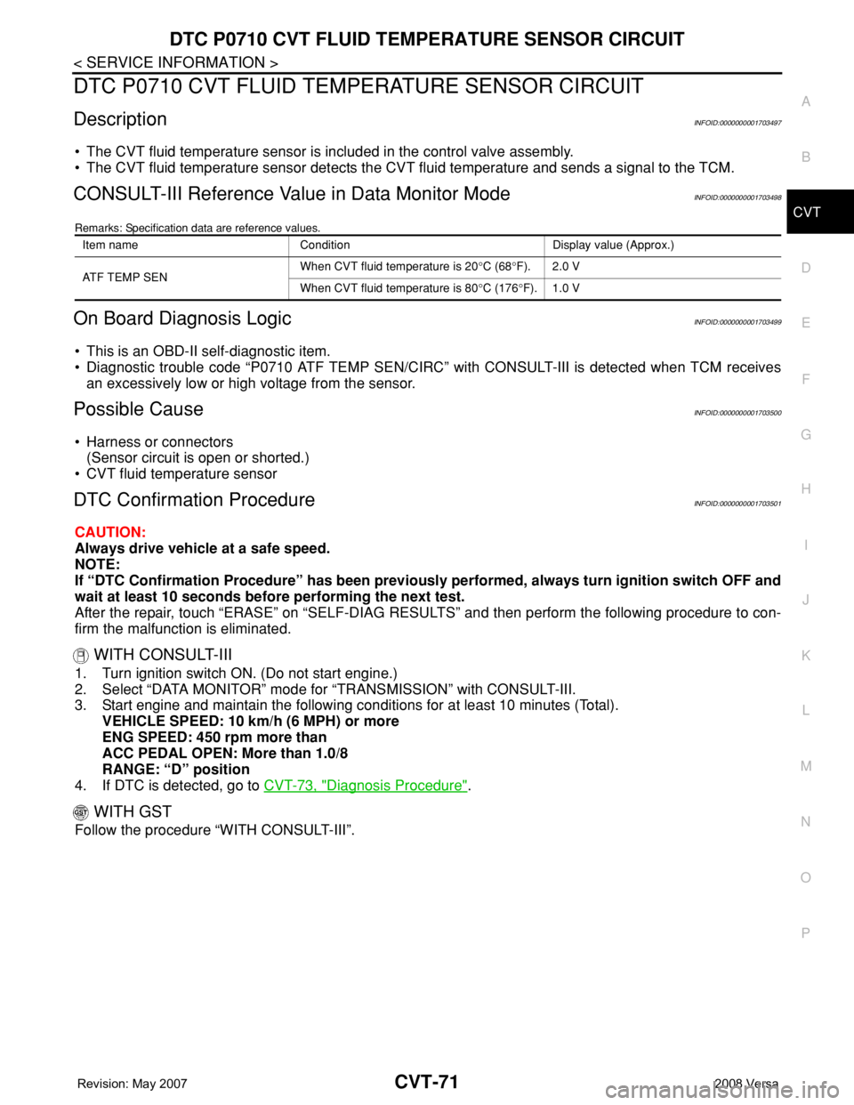
CONSULT-III Reference Value in Data Monitor ModeINFOID:0000000001703498
Remarks: Specification data are reference values.
On Board Diagnosis LogicINFOID:0000000001703499
• This is an OBD-II self-diagnostic item.
• Diagnostic trouble code “P0710 ATF TEMP SEN/CIRC” with CONSULT-III is detected when TCM receives
an excessively low or high voltage from the sensor.
Possible CauseINFOID:0000000001703500
• Harness or connectors
(Sensor circuit is open or shorted.)
• CVT fluid temperature sensor
DTC Confirmation ProcedureINFOID:0000000001703501
CAUTION:
Always drive vehicle at a safe speed.
NOTE:
If “DTC Confirmation Procedure” has been previously performed, always turn ignition switch OFF and
wait at least 10 seconds before performing the next test.
After the repair, touch “ERASE” on “SELF-DIAG RESULTS” and then perform the following procedure to con-
firm the malfunction is eliminated.
WITH CONSULT-III
1. Turn ignition switch ON. (Do not start engine.)
2. Select “DATA MONITOR” mode for “TRANSMISSION” with CONSULT-III.
3. Start engine and maintain the following conditions for at least 10 minutes (Total).
VEHICLE SPEED: 10 km/h (6 MPH) or more
ENG SPEED: 450 rpm more than
ACC PEDAL OPEN: More than 1.0/8
RANGE: “D” position
4. If DTC is detected, go to CVT-73, "
Diagnosis Procedure".
WITH GST
Follow the procedure “WITH CONSULT-III”.
Item name Condition Display value (Approx.)
ATF TEMP SEN When CVT fluid temperature is 20°C (68°F). 2.0 V
When CVT fluid temperature is 80°C (176°F). 1.0 V
Page 915 of 2771
CVT-76
< SERVICE INFORMATION >
DTC P0715 INPUT SPEED SENSOR CIRCUIT (PRI SPEED SENSOR)
DTC P0715 INPUT SPEED SENSOR CIRCUIT (PRI SPEED SENSOR)
DescriptionINFOID:0000000001703505
• The input speed sensor (primary speed sensor) is included in the control valve assembly.
• The input speed sensor (primary speed sensor) detects the primary pulley revolution speed and sends a sig-
nal to the TCM.
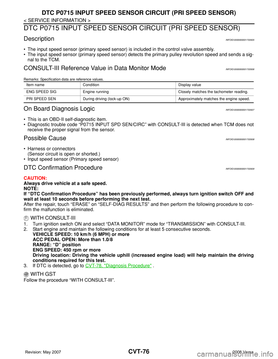
CONSULT-III Reference Value in Data Monitor ModeINFOID:0000000001703506
Remarks: Specification data are reference values.
On Board Diagnosis LogicINFOID:0000000001703507
• This is an OBD-II self-diagnostic item.
• Diagnostic trouble code “P0715 INPUT SPD SEN/CIRC” with CONSULT-III is detected when TCM does not
receive the proper signal from the sensor.
Possible CauseINFOID:0000000001703508
• Harness or connectors
(Sensor circuit is open or shorted.)
• Input speed sensor (Primary speed sensor)
DTC Confirmation ProcedureINFOID:0000000001703509
CAUTION:
Always drive vehicle at a safe speed.
NOTE:
If “DTC Confirmation Procedure” has been previously performed, always turn ignition switch OFF and
wait at least 10 seconds before performing the next test.
After the repair, touch “ERASE” on “SELF-DIAG RESULTS” and then perform the following procedure to con-
firm the malfunction is eliminated.
WITH CONSULT-III
1. Turn ignition switch ON and select “DATA MONITOR” mode for “TRANSMISSION” with CONSULT-III.
2. Start engine and maintain the following conditions for at least 5 consecutive seconds.
VEHICLE SPEED: 10 km/h (6 MPH) or more
ACC PEDAL OPEN: More than 1.0/8
RANGE: “D” position
ENG SPEED: 450 rpm or more
Driving location: Driving the vehicle uphill (increased engine load) will help maintain the driving
conditions required for this test.
3. If DTC is detected, go to CVT-78, "
Diagnosis Procedure" .
WITH GST
Follow the procedure “WITH CONSULT-III”.
Item name Condition Display value
ENG SPEED SIG Engine running Closely matches the tachometer reading.
PRI SPEED SEN During driving (lock-up ON) Approximately matches the engine speed.