2008 INFINITI FX35 check engine
[x] Cancel search: check enginePage 3344 of 3924
CHASSIS AND BODY MAINTENANCEMA-27
< SERVICE INFORMATION >
C
DE
F
G H
I
J
K
M A
B
MA
N
O P
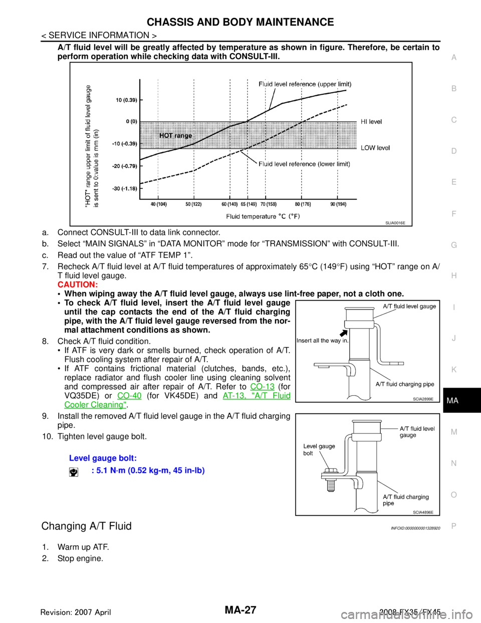
A/T fluid level will be greatly affected by temper ature as shown in figure. Therefore, be certain to
perform operation while checki ng data with CONSULT-III.
a. Connect CONSULT-III to data link connector.
b. Select “MAIN SIGNALS” in “DATA MONITOR” mode for “TRANSMISSION” with CONSULT-III.
c. Read out the value of “ATF TEMP 1”.
7. Recheck A/T fluid level at A/T fluid temperatures of approximately 65 °C (149 °F) using “HOT” range on A/
T fluid level gauge.
CAUTION:
When wiping away the A/T fluid level gauge, always use lint-free paper, not a cloth one.
To check A/T fluid level, inser t the A/T fluid level gauge
until the cap contacts the en d of the A/T fluid charging
pipe, with the A/T fluid level gauge reversed from the nor-
mal attachment conditions as shown.
8. Check A/T fluid condition. If ATF is very dark or smells burned, check operation of A/T.
Flush cooling system after repair of A/T.
If ATF contains frictional material (clutches, bands, etc.), replace radiator and flush cooler line using cleaning solvent
and compressed air after repair of A/T. Refer to CO-13
(for
VQ35DE) or CO-40
(for VK45DE) and AT-13, "A/T Fluid
Cooler Cleaning".
9. Install the removed A/T fluid level gauge in the A/T fluid charging pipe.
10. Tighten level gauge bolt.
Changing A/T FluidINFOID:0000000001328920
1. Warm up ATF.
2. Stop engine. Level gauge bolt:
: 5.1 N·m (0.52 kg-m, 45 in-lb)
SLIA0016E
SCIA2899E
SCIA4896E
3AA93ABC3ACD3AC03ACA3AC03AC63AC53A913A773A893A873A873A8E3A773A983AC73AC93AC03AC3
3A893A873A873A8F3A773A9D3AAF3A8A3A8C3A863A9D3AAF3A8B3A8C
Page 3345 of 3924
MA-28
< SERVICE INFORMATION >
CHASSIS AND BODY MAINTENANCE
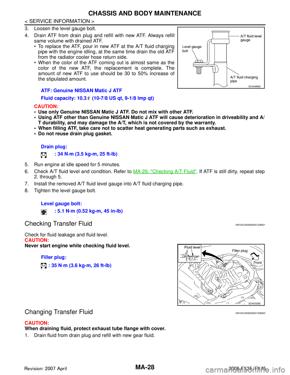
3. Loosen the level gauge bolt.
4. Drain ATF from drain plug and refill with new ATF. Always refillsame volume with drained ATF.
To replace the ATF, pour in new ATF at the A/T fluid charging
pipe with the engine idling, at the same time drain the old ATF
from the radiator cooler hose return side.
When the color of the ATF coming out is almost same as the color of the new ATF, the replacement is complete. The
amount of new ATF to use should be 30 to 50% increase of
the stipulated amount.
CAUTION:
Use only Genuine NISSAN Matic J ATF. Do not mix with other ATF.
Using ATF other than Genuine NISSAN Matic J AT F will cause deterioration in driveability and A/
T durability, and may damage the A/T, which is not covered by the warranty.
When filling ATF, take care not to scatter heat generating parts such as exhaust.
Do not reuse drain plug gasket.
5. Run engine at idle speed for 5 minutes.
6. Check A/T fluid level and condition. Refer to MA-26, "
Checking A/T Fluid". If ATF is still dirty, repeat step
2. through 5.
7. Install the removed A/T fluid level gauge into A/T fluid charging pipe.
8. Tighten the level gauge bolt.
Checking Transfer FluidINFOID:0000000001328921
Check for fluid leakage and fluid level.
CAUTION:
Never start engine while checking fluid level.
Changing Transfer FluidINFOID:0000000001328922
CAUTION:
When draining fluid, protect exh aust tube flange with cover.
1. Drain fluid from drain plug and refill with new gear fluid. ATF: Genuine NISSAN Matic J ATF
Fluid capacity: 10.3 (10-7/8 US qt, 9-1/8 lmp qt)
Drain plug:
: 34 N·m (3.5 kg-m, 25 ft-lb)
Level gauge bolt: : 5.1 N·m (0.52 kg-m, 45 in-lb)
SCIA4896E
Filler plug:
: 35 N·m (3.6 kg-m, 26 ft-lb)
SDIA2028E
3AA93ABC3ACD3AC03ACA3AC03AC63AC53A913A773A893A873A873A8E3A773A983AC73AC93AC03AC3
3A893A873A873A8F3A773A9D3AAF3A8A3A8C3A863A9D3AAF3A8B3A8C
Page 3350 of 3924
CHASSIS AND BODY MAINTENANCEMA-33
< SERVICE INFORMATION >
C
DE
F
G H
I
J
K
M A
B
MA
N
O P
PA D
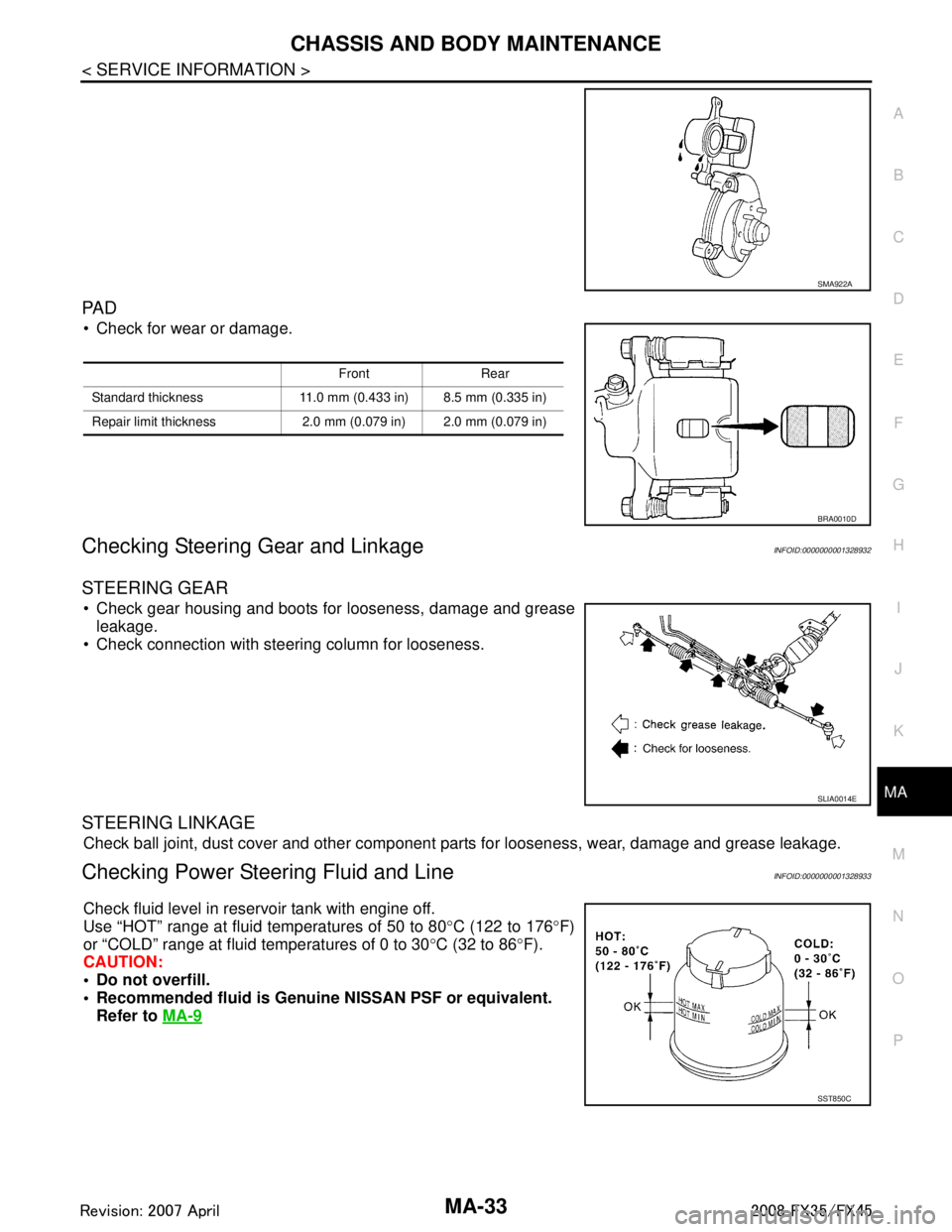
Check for wear or damage.
Checking Steering Ge ar and LinkageINFOID:0000000001328932
STEERING GEAR
Check gear housing and boots for looseness, damage and grease
leakage.
Check connection with steering column for looseness.
STEERING LINKAGE
Check ball joint, dust cover and other component parts for looseness, wear, damage and grease leakage.
Checking Power Steering Fluid and LineINFOID:0000000001328933
Check fluid level in reservoir tank with engine off.
Use “HOT” range at fluid temperatures of 50 to 80 °C (122 to 176 °F)
or “COLD” range at fluid temperatures of 0 to 30 °C (32 to 86 °F).
CAUTION:
Do not overfill.
Recommended fluid is Genuin e NISSAN PSF or equivalent.
Refer to MA-9
SMA922A
Front Rear
Standard thickness 11.0 mm (0.433 in) 8.5 mm (0.335 in)
Repair limit thickness 2.0 mm (0.079 in) 2.0 mm (0.079 in)
BRA0010D
SLIA0014E
SST850C
3AA93ABC3ACD3AC03ACA3AC03AC63AC53A913A773A893A873A873A8E3A773A983AC73AC93AC03AC3
3A893A873A873A8F3A773A9D3AAF3A8A3A8C3A863A9D3AAF3A8B3A8C
Page 3354 of 3924
SERVICE DATA AND SPECIFICATIONS (SDS)
MA-37
< SERVICE INFORMATION >
C
D E
F
G H
I
J
K
M A
B
MA
N
O P
SERVICE DATA AND SPECIFICATIONS (SDS)
Standard and LimitINFOID:0000000001328938
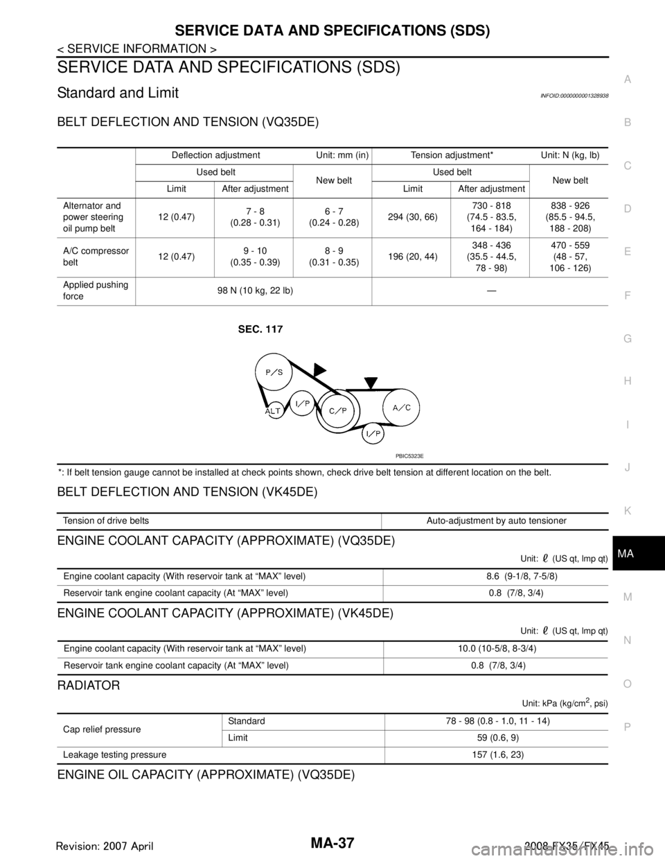
BELT DEFLECTION AND TENSION (VQ35DE)
*: If belt tension gauge cannot be installed at check points shown, check drive belt tension at different location on the belt.
BELT DEFLECTION AND TENSION (VK45DE)
ENGINE COOLANT CAPACITY (APPROXIMATE) (VQ35DE)
Unit: (US qt, lmp qt)
ENGINE COOLANT CAPACITY (APPROXIMATE) (VK45DE)
Unit: (US qt, lmp qt)
RADIATOR
Unit: kPa (kg/cm2, psi)
ENGINE OIL CAPACITY (APPROXIMATE) (VQ35DE)
Deflection adjustment Unit: mm (in) Tension adjustment* Unit: N (kg, lb) Used belt New beltUsed belt
New belt
Limit After adjustment Limit After adjustment
Alternator and
power steering
oil pump belt 12 (0.47)
7 - 8
(0.28 - 0.31) 6 - 7
(0.24 - 0.28) 294 (30, 66) 730 - 818
(74.5 - 83.5, 164 - 184) 838 - 926
(85.5 - 94.5, 188 - 208)
A/C compressor
belt 12 (0.47)
9 - 10
(0.35 - 0.39) 8 - 9
(0.31 - 0.35) 196 (20, 44) 348 - 436
(35.5 - 44.5,
78 - 98) 470 - 559
(48 - 57,
106 - 126)
Applied pushing
force 98 N (10 kg, 22 lb) —
PBIC5323E
Tension of drive belts Auto-adjustment by auto tensioner
Engine coolant capacity (With reservoir tank at “MAX” level) 8.6 (9-1/8, 7-5/8)
Reservoir tank engine coolant capacity (At “MAX” level) 0.8 (7/8, 3/4)
Engine coolant capacity (With reservoir tank at “MAX” level) 10.0 (10-5/8, 8-3/4)
Reservoir tank engine coolant capacity (At “MAX” level) 0.8 (7/8, 3/4)
Cap relief pressure Standard 78 - 98 (0.8 - 1.0, 11 - 14)
Limit 59 (0.6, 9)
Leakage testing pressure 157 (1.6, 23)
3AA93ABC3ACD3AC03ACA3AC03AC63AC53A913A773A893A873A873A8E3A773A983AC73AC93AC03AC3
3A893A873A873A8F3A773A9D3AAF3A8A3A8C3A863A9D3AAF3A8B3A8C
Page 3382 of 3924

PG-18
< SERVICE INFORMATION >
IPDM E/R (INTELLIGENT POWER DISTRIBUTION MODULE ENGINE ROOM)
All systems controlled by IPDM E/R are stopped. When 3 seconds have elapsed after CAN communica-
tion with other control units is st opped, mode switches to sleep status.
3. Sleep status IPDM E/R operates in low power mode.
CAN communication is stopped.
When a change in CAN communication line is detected, mode switches to CAN communication status.
When a change hood switch or ignition switch signal is detected, mode switches to CAN communication
status.
CAN Communication System DescriptionINFOID:0000000001328871
CAN (Controller Area Network) is a serial communication line for real time application. It is an on-vehicle mul-
tiplex communication line with high data communication speed and excellent error detection ability. Modern
vehicles are equipped with many electronic control units and each control unit shares information and links
with other control units during operation (not independent ). In CAN communication, control units are con-
nected with 2 communication lines (CAN-H line, CAN-L line) allowing a high rate of information transmission
with less wiring. Each control unit transmits/recei ves data but selectively reads required data only.
CAN Communication UnitINFOID:0000000001328872
Refer to LAN-43, "CAN System Specification Chart".
Function of Detecting I gnition Relay MalfunctionINFOID:0000000001328873
When contact point of integrated ignition relay is st uck and cannot be turned OFF, IPDM E/R turns ON park-
ing, license plate, side marker and tail lamps for 10 minutes to indicate ignition relay malfunction.
When a state of ignition relay having built-in does not agr ee with a state of ignition switch signal input by a
CAN communication from BCM, IPDM E/R lets tail lamp relay operate.
NOTE:
When the ignition switch is turned ON, the tail lamps are OFF.
CONSULT-III Function (IPDM E/R)INFOID:0000000001328874
CONSULT-III can display each diagnostic item using the diagnostic test mode shown following.
Self Diagnostic Result
Display Item List
Ignition switch signal Ignition relay status Tail lamp relay
ON ON —
OFF OFF — ON OFF —
OFF ON ON (10 minutes)
Inspection Item, Diagnosis Mode Description
Self Diagnostic Result The IPDM E/R performs diagnosis of the CAN communication and self-diagnosis.
Data Monitor The input/output data of the IPDM E/R is displayed in real time.
CAN Diag Support Monitor The result of transmit/receive diagnosis of CAN communication can be read.
Active test The IPDM E/R sends a drive signal to electronic components to check their operation.
3AA93ABC3ACD3AC03ACA3AC03AC63AC53A913A773A893A873A873A8E3A773A983AC73AC93AC03AC3
3A893A873A873A8F3A773A9D3AAF3A8A3A8C3A863A9D3AAF3A8B3A8C
Page 3384 of 3924
PG-20
< SERVICE INFORMATION >
IPDM E/R (INTELLIGENT POWER DISTRIBUTION MODULE ENGINE ROOM)
NOTE:
This item is displayed, but cannot be tested.
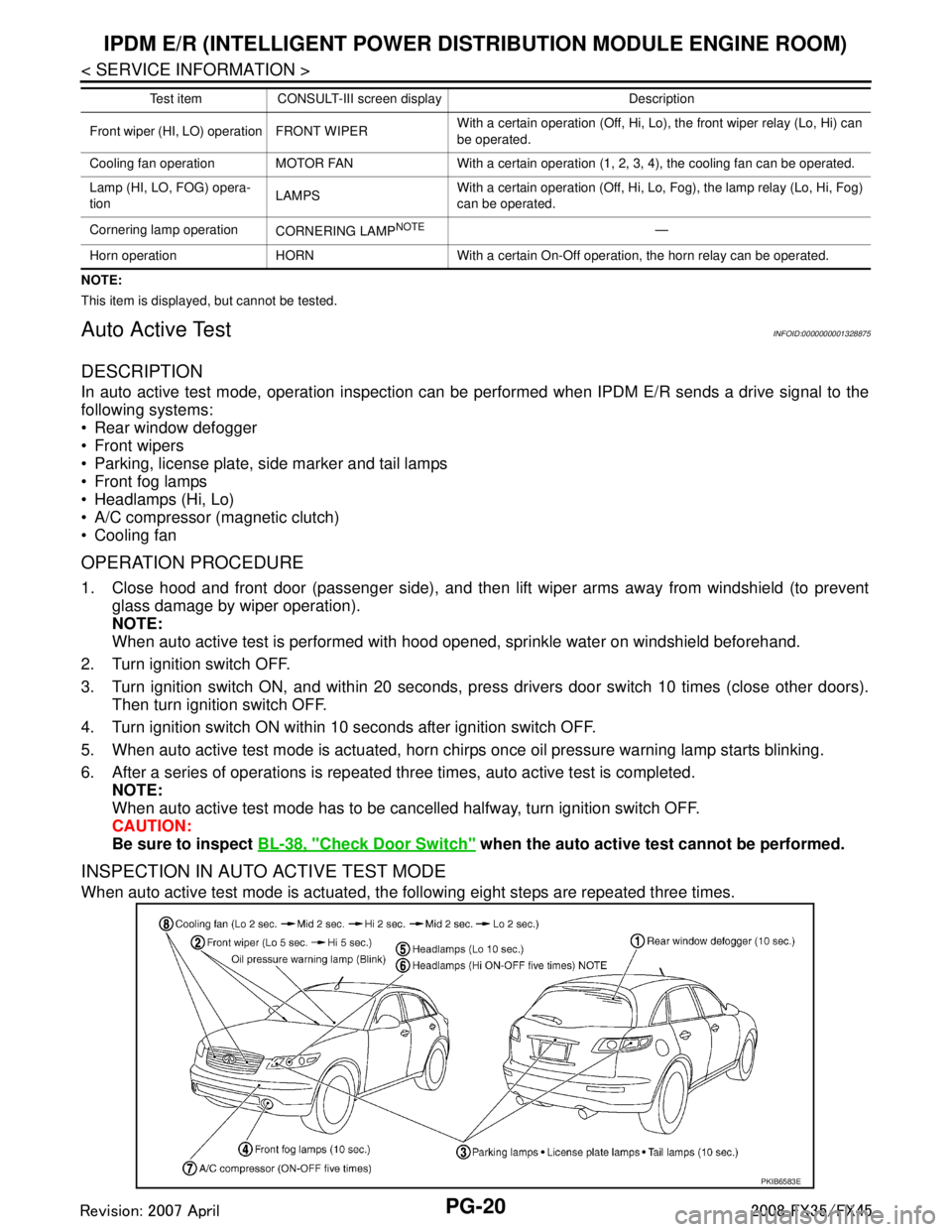
Auto Active TestINFOID:0000000001328875
DESCRIPTION
In auto active test mode, operation inspection can be performed when IPDM E/R sends a drive signal to the
following systems:
Rear window defogger
Front wipers
Parking, license plate, side marker and tail lamps
Front fog lamps
Headlamps (Hi, Lo)
A/C compressor (magnetic clutch)
Cooling fan
OPERATION PROCEDURE
1. Close hood and front door (passenger side), and then lift wiper arms away from windshield (to prevent
glass damage by wiper operation).
NOTE:
When auto active test is performed with hood opened, sprinkle water on windshield beforehand.
2. Turn ignition switch OFF.
3. Turn ignition switch ON, and within 20 seconds, pre ss drivers door switch 10 times (close other doors).
Then turn ignition switch OFF.
4. Turn ignition switch ON within 10 seconds after ignition switch OFF.
5. When auto active test mode is actuated, horn chir ps once oil pressure warning lamp starts blinking.
6. After a series of operations is repeated three times, auto active test is completed. NOTE:
When auto active test mode has to be cancelled halfway, turn ignition switch OFF.
CAUTION:
Be sure to inspect BL-38, "
Check Door Switch" when the auto active t est cannot be performed.
INSPECTION IN AUTO ACTIVE TEST MODE
When auto active test mode is actuated, the following eight steps are repeated three times.
Front wiper (HI, LO) operation FRONT WIPER With a certain operation (Off, Hi, Lo),
the front wiper relay (Lo, Hi) can
be operated.
Cooling fan operation MOTOR FAN With a certain operation (1, 2, 3, 4), the cooling fan can be operated.
Lamp (HI, LO, FOG) opera-
tion LAMPSWith a certain operation (Off, Hi, Lo, Fog), the lamp relay (Lo, Hi, Fog)
can be operated.
Cornering lamp operation CORNERING LAMP
NOTE—
Horn operation HORN With a certain On-Off operation, the horn relay can be operated. Test item CONSULT-III screen display Description
PKIB6583E
3AA93ABC3ACD3AC03ACA3AC03AC63AC53A913A773A893A873A873A8E3A773A983AC73AC93AC03AC3
3A893A873A873A8F3A773A9D3AAF3A8A3A8C3A863A9D3AAF3A8B3A8C
Page 3387 of 3924
IPDM E/R (INTELLIGENT POWER DISTRIBUTION MODULE ENGINE ROOM)
PG-23
< SERVICE INFORMATION >
C
D E
F
G H
I
J
L
M A
B
PG
N
O P
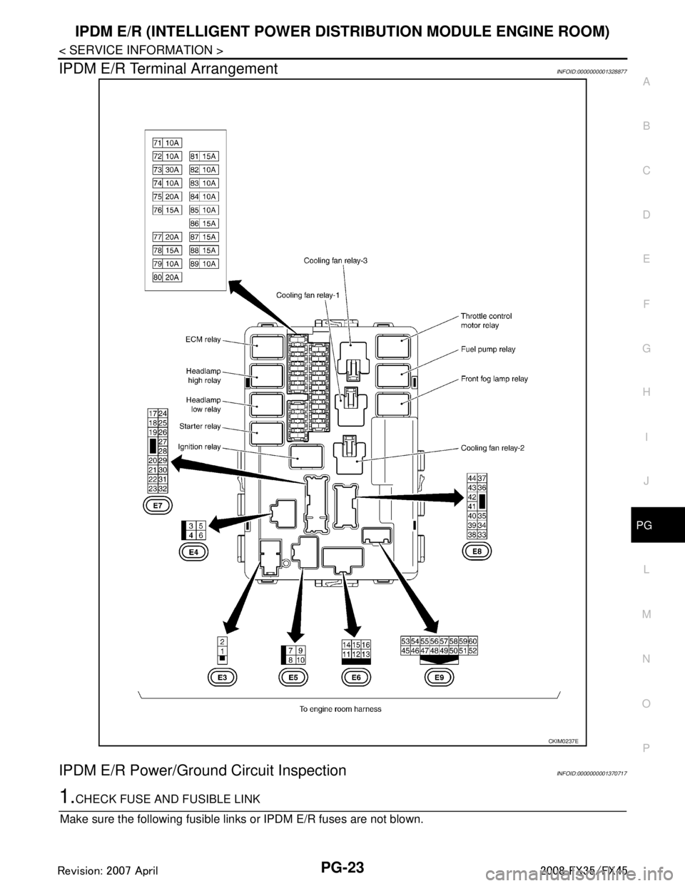
IPDM E/R Terminal ArrangementINFOID:0000000001328877
IPDM E/R Power/Ground Circuit InspectionINFOID:0000000001370717
1.CHECK FUSE AND FUSIBLE LINK
Make sure the following fusible links or IPDM E/R fuses are not blown.
CKIM0237E
3AA93ABC3ACD3AC03ACA3AC03AC63AC53A913A773A893A873A873A8E3A773A983AC73AC93AC03AC3
3A893A873A873A8F3A773A9D3AAF3A8A3A8C3A863A9D3AAF3A8B3A8C
Page 3388 of 3924
PG-24
< SERVICE INFORMATION >
IPDM E/R (INTELLIGENT POWER DISTRIBUTION MODULE ENGINE ROOM)
OK or NG
OK >> GO TO 2.
NG >> If fuse or fusible link blown, be sure to e liminate cause of malfunction before installing new one.
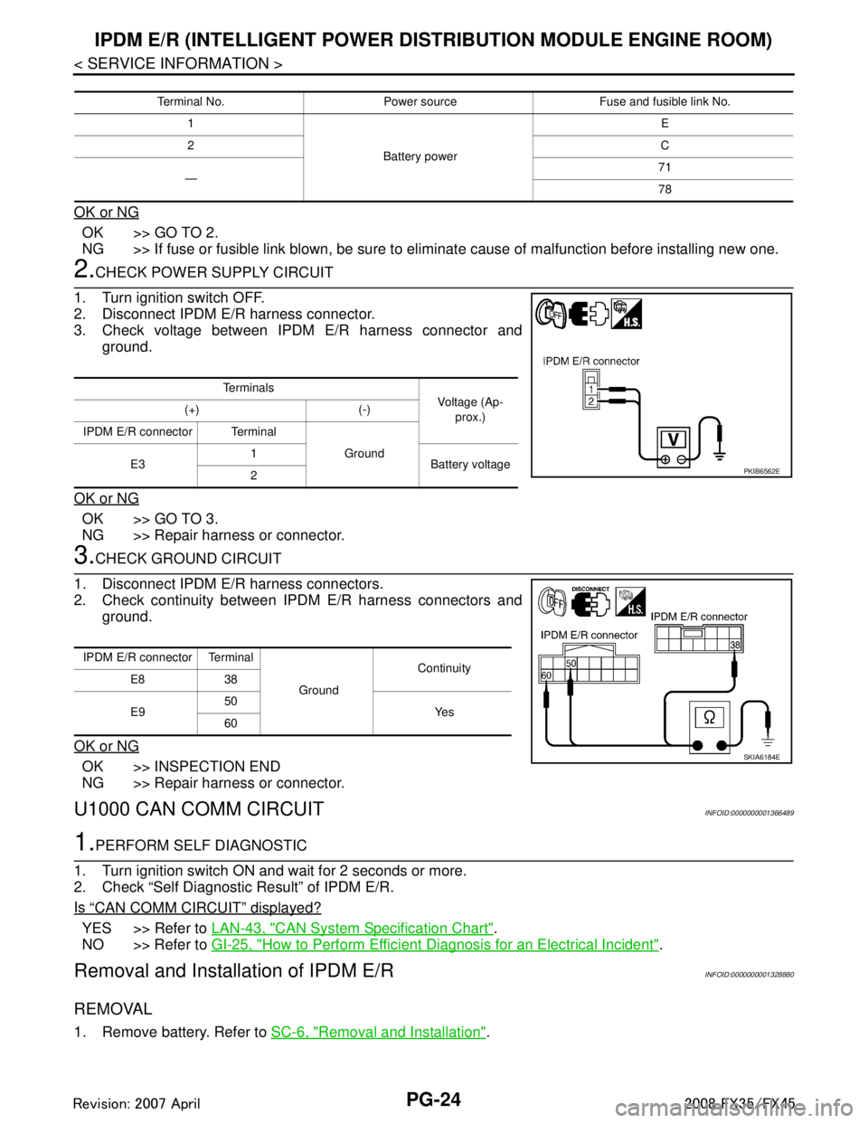
2.CHECK POWER SUPPLY CIRCUIT
1. Turn ignition switch OFF.
2. Disconnect IPDM E/R harness connector.
3. Check voltage between IPDM E/R harness connector and ground.
OK or NG
OK >> GO TO 3.
NG >> Repair harness or connector.
3.CHECK GROUND CIRCUIT
1. Disconnect IPDM E/R harness connectors.
2. Check continuity between IPDM E/R harness connectors and ground.
OK or NG
OK >> INSPECTION END
NG >> Repair harness or connector.
U1000 CAN COMM CIRCUITINFOID:0000000001366489
1.PERFORM SELF DIAGNOSTIC
1. Turn ignition switch ON and wait for 2 seconds or more.
2. Check “Self Diagnostic Result” of IPDM E/R.
Is
“CAN COMM CIRCUIT” displayed?
YES >> Refer to LAN-43, "CAN System Specification Chart".
NO >> Refer to GI-25, "
How to Perform Efficient Diagnosis for an Electrical Incident".
Removal and Installation of IPDM E/RINFOID:0000000001328880
REMOVAL
1. Remove battery. Refer to SC-6, "Removal and Installation".
Terminal No. Power source Fuse and fusible link No.
1
Battery power E
2 C
— 71
78
Te r m i n a l s
Voltage (Ap-
prox.)
(+) (-)
IPDM E/R connector Terminal Ground
E3 1
Battery voltage
2
PKIB6562E
IPDM E/R connector Terminal
GroundContinuity
E8 38
E9 50
Ye s
60
SKIA6184E
3AA93ABC3ACD3AC03ACA3AC03AC63AC53A913A773A893A873A873A8E3A773A983AC73AC93AC03AC3
3A893A873A873A8F3A773A9D3AAF3A8A3A8C3A863A9D3AAF3A8B3A8C