Page 3290 of 3924
![INFINITI FX35 2008 Service Manual
ENGINE OILLU-5
< SERVICE INFORMATION > [VQ35DE]
C
D
E
F
G H
I
J
K L
M A
LU
NP
O
ENGINE OIL
InspectionINFOID:0000000001325813
ENGINE OIL LEVEL
NOTE:
Before starting engine, put vehicle horizontally an INFINITI FX35 2008 Service Manual
ENGINE OILLU-5
< SERVICE INFORMATION > [VQ35DE]
C
D
E
F
G H
I
J
K L
M A
LU
NP
O
ENGINE OIL
InspectionINFOID:0000000001325813
ENGINE OIL LEVEL
NOTE:
Before starting engine, put vehicle horizontally an](/manual-img/42/57017/w960_57017-3289.png)
ENGINE OILLU-5
< SERVICE INFORMATION > [VQ35DE]
C
D
E
F
G H
I
J
K L
M A
LU
NP
O
ENGINE OIL
InspectionINFOID:0000000001325813
ENGINE OIL LEVEL
NOTE:
Before starting engine, put vehicle horizontally and check
the engine oil level. If engine is already started, stop
it and allow 10 minutes before checking.
1. Pull out oil level gauge and wipe it clean.
2. Insert oil level gauge and make sure the engine oil level is within the range shown in the figure.
3. If it is out of range, adjust it.
NOTE:
When checking the engine oil level, insert oil level gauge with its
tip aligned with oil level gauge guide on cylinder head. (In figure,
air cleaner case and air duct are removed.)
ENGINE OIL APPEARANCE
Check engine oil for white turbidity or heavy contamination.
If engine oil becomes turbid and white, it is highl y probable that it is contaminated with engine coolant.
Repair or replace damaged parts.
ENGINE OIL LEAKAGE
Check for engine oil leakage around the following areas:
Oil pans (lower and upper)
Oil pan drain plug
Oil pressure switch
Oil filter
Oil filter bracket (AWD models)
Oil cooler
Water pump cover
Chain tensioner cover
Intake valve timing control cover and intake valve timing control solenoid valve
Mating surface between cylinder head and rocker cover
Mating surface between front timing chain case and rear timing chain case
Mating surface between rear timing chain case and cylinder head
Mating surface between rear timing chain case and cylinder block
Mating surface between rear timing chain case and oil pan (upper)
Mating surface between cylinder block and cylinder head
Crankshaft oil seals (front and rear)
Camshaft position sensor (PHASE)
OIL PRESSURE CHECK
PBIC3101E
KBIA1343E
3AA93ABC3ACD3AC03ACA3AC03AC63AC53A913A773A893A873A873A8E3A773A983AC73AC93AC03AC3
3A893A873A873A8F3A773A9D3AAF3A8A3A8C3A863A9D3AAF3A8B3A8C
Page 3336 of 3924

ENGINE MAINTENANCE (VK45DE ENGINE)MA-19
< SERVICE INFORMATION >
C
DE
F
G H
I
J
K
M A
B
MA
N
O P
ENGINE MAINTENANCE (VK45DE ENGINE)
Checking Drive BeltsINFOID:0000000001328909
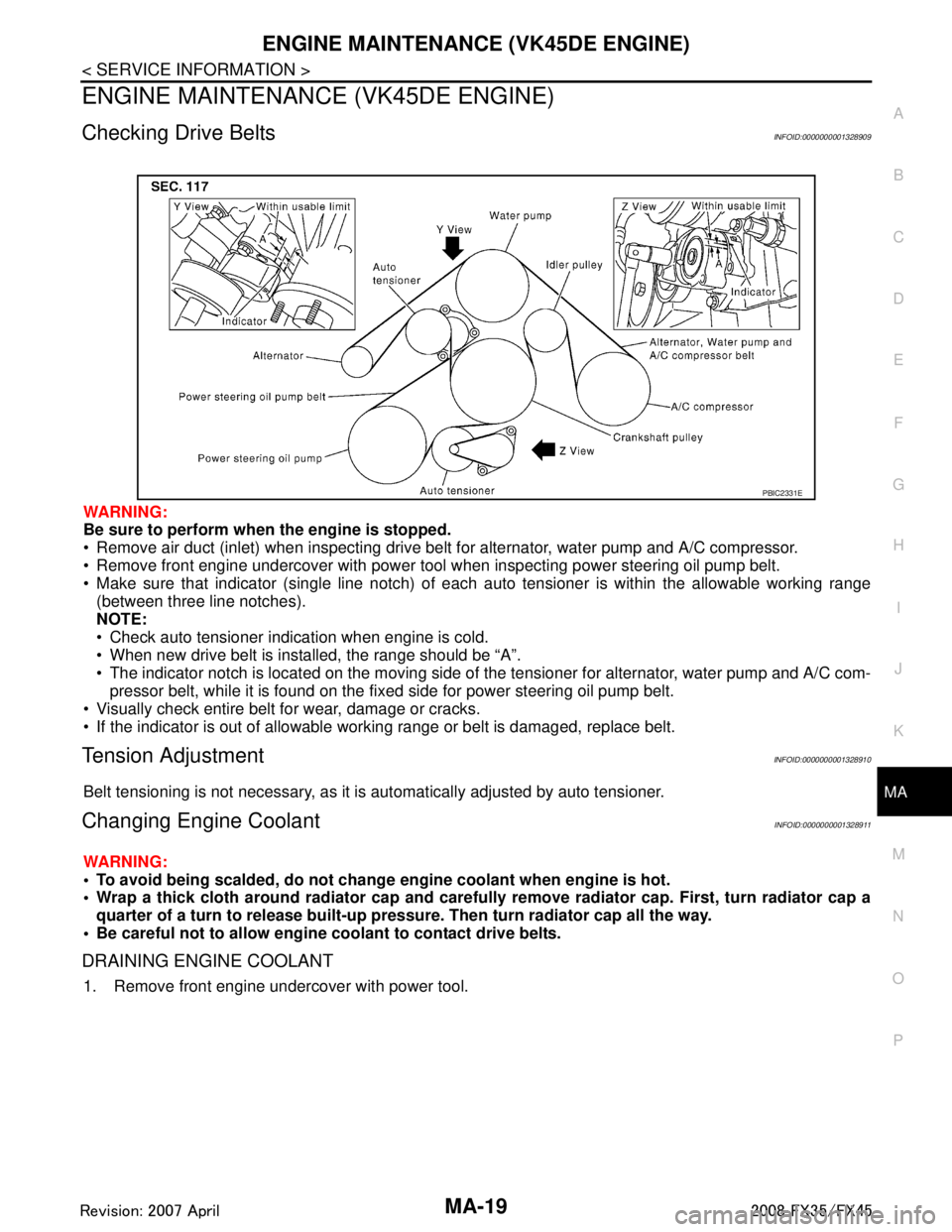
WARNING:
Be sure to perform when the engine is stopped.
Remove air duct (inlet) when inspecting drive belt for alternator, water pump and A/C compressor.
Remove front engine undercover with power tool when inspecting power steering oil pump belt.
Make sure that indicator (single line notch) of eac h auto tensioner is within the allowable working range
(between three line notches).
NOTE:
Check auto tensioner indication when engine is cold.
When new drive belt is installed, the range should be “A”.
The indicator notch is located on the moving side of the tensioner for alternator, water pump and A/C com-
pressor belt, while it is found on the fi xed side for power steering oil pump belt.
Visually check entire belt for wear, damage or cracks.
If the indicator is out of allowable working range or belt is damaged, replace belt.
Tension AdjustmentINFOID:0000000001328910
Belt tensioning is not necessary, as it is automatically adjusted by auto tensioner.
Changing Engine CoolantINFOID:0000000001328911
WARNING:
To avoid being scalded, do not change engine coolant when engine is hot.
Wrap a thick cloth around radiator cap and carefully remove radiator cap. First, turn radiator cap a
quarter of a turn to release built-up pressu re. Then turn radiator cap all the way.
Be careful not to allow engine coolant to contact drive belts.
DRAINING ENGINE COOLANT
1. Remove front engine undercover with power tool.
PBIC2331E
3AA93ABC3ACD3AC03ACA3AC03AC63AC53A913A773A893A873A873A8E3A773A983AC73AC93AC03AC3
3A893A873A873A8F3A773A9D3AAF3A8A3A8C3A863A9D3AAF3A8B3A8C
Page 3635 of 3924
SC-26
< SERVICE INFORMATION >
CHARGING SYSTEM
4. Remove alternator, water pump and A/C compressor belt. Refer to EM-170, "Removal and Installation".
5. Remove alternator mounting bolts, using power tools.
6. Disconnect alternator connector.
7. Remove “B” terminal nut.
8. Remove alternator ground harness mounting bolt.
9. Remove alternator assembly downward from the vehicle.
ALTERNATOR PULLEY INSPECTION
Perform the following.
Make sure that alternator pulley does not rattle.
Make sure that alternator pulley nut is tight.
INSTALLATION
Installation is the reverse order of removal. Install alternator, and check tension of belt. Refer to EM-170, "Checking Drive Belts".
CAUTION:
Be sure to tighten “B” terminal nut carefully.
PKIA2954E
PKIA2820E
Alternator pulley nut:
: 73.5 N·m (7.5 kg-m, 54 ft-lb)
3AA93ABC3ACD3AC03ACA3AC03AC63AC53A913A773A893A873A873A8E3A773A983AC73AC93AC03AC3
3A893A873A873A8F3A773A9D3AAF3A8A3A8C3A863A9D3AAF3A8B3A8C
Page 3636 of 3924

CHARGING SYSTEMSC-27
< SERVICE INFORMATION >
C
DE
F
G H
I
J
L
M A
B
SC
N
O P
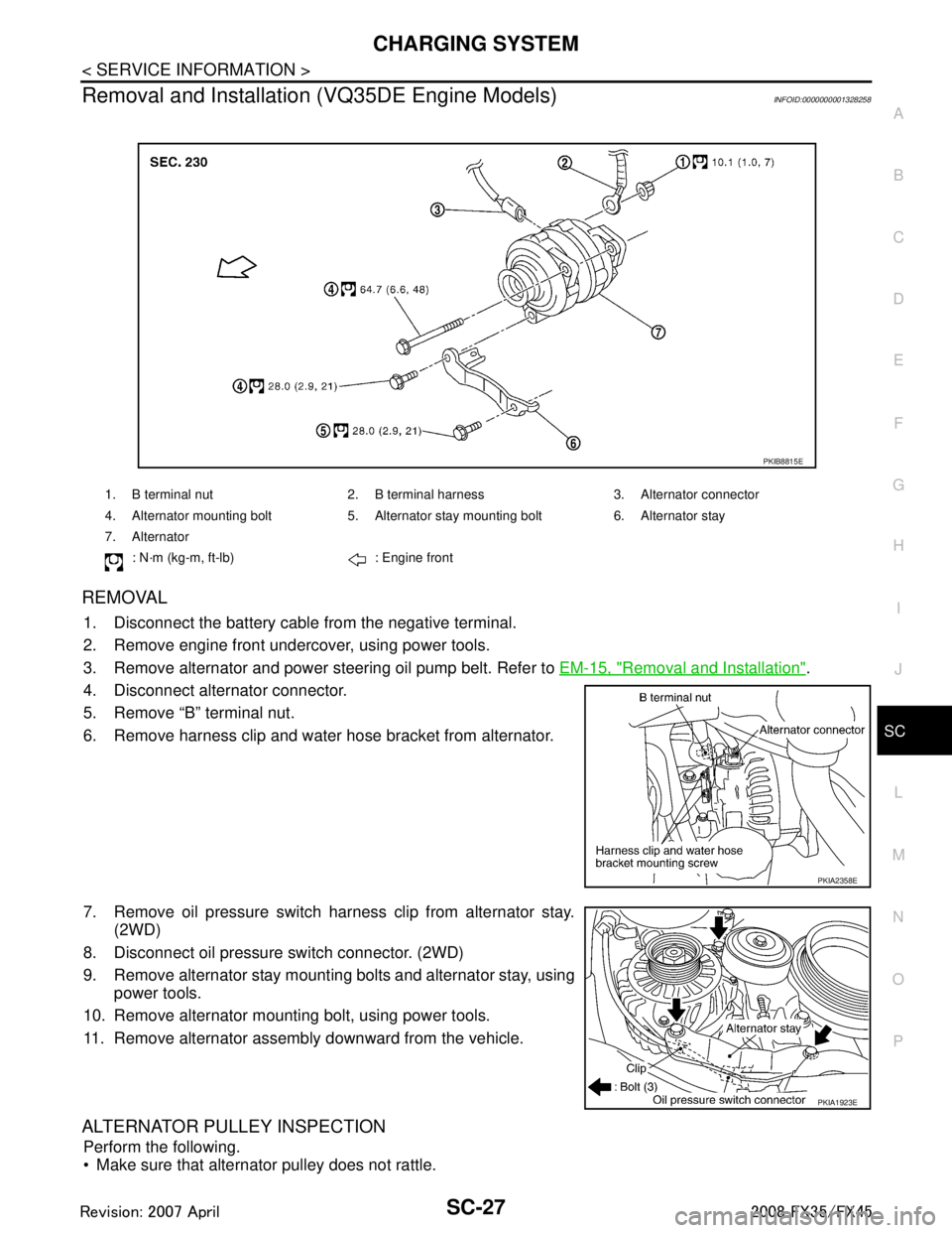
Removal and Installation (VQ35DE Engine Models)INFOID:0000000001328258
REMOVAL
1. Disconnect the battery cabl e from the negative terminal.
2. Remove engine front undercover, using power tools.
3. Remove alternator and power steering oil pump belt. Refer to EM-15, "
Removal and Installation".
4. Disconnect alternator connector.
5. Remove “B” terminal nut.
6. Remove harness clip and water hose bracket from alternator.
7. Remove oil pressure switch harness clip from alternator stay. (2WD)
8. Disconnect oil pressure switch connector. (2WD)
9. Remove alternator stay mounting bolts and alternator stay, using power tools.
10. Remove alternator mounting bolt, using power tools.
11. Remove alternator assembly downward from the vehicle.
ALTERNATOR PULLEY INSPECTION
Perform the following.
Make sure that alternator pulley does not rattle.
1. B terminal nut 2. B terminal harness 3. Alternator connector
4. Alternator mounting bolt 5. Alternator stay mounting bolt 6. Alternator stay
7. Alternator
: N·m (kg-m, ft-lb) : Engine front
PKIB8815E
PKIA2358E
PKIA1923E
3AA93ABC3ACD3AC03ACA3AC03AC63AC53A913A773A893A873A873A8E3A773A983AC73AC93AC03AC3
3A893A873A873A8F3A773A9D3AAF3A8A3A8C3A863A9D3AAF3A8B3A8C
Page 3904 of 3924

FRONT WIPER AND WASHER SYSTEMWW-29
< SERVICE INFORMATION >
C
DE
F
G H
I
J
L
M A
B
WW
N
O P
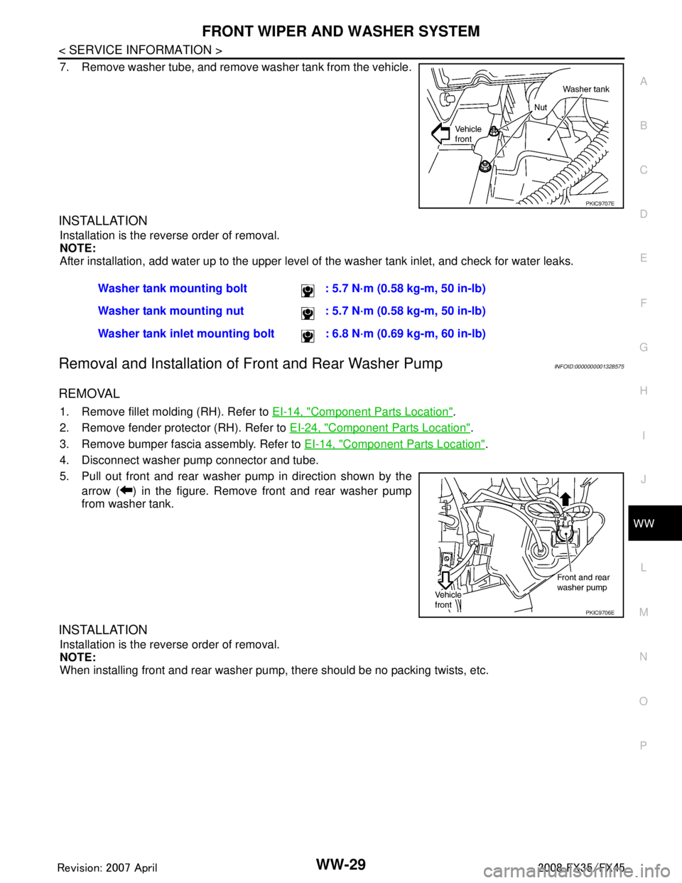
7. Remove washer tube, and remove washer tank from the vehicle.
INSTALLATION
Installation is the reverse order of removal.
NOTE:
After installation, add water up to the upper level of the washer tank inlet, and check for water leaks.
Removal and Installation of Front and Rear Washer PumpINFOID:0000000001328575
REMOVAL
1. Remove fillet molding (RH). Refer to EI-14, "Component Parts Location".
2. Remove fender protector (RH). Refer to EI-24, "
Component Parts Location".
3. Remove bumper fascia assembly. Refer to EI-14, "
Component Parts Location".
4. Disconnect washer pump connector and tube.
5. Pull out front and rear washer pump in direction shown by the arrow ( ) in the figure. Remove front and rear washer pump
from washer tank.
INSTALLATION
Installation is the reverse order of removal.
NOTE:
When installing front and rear washer pump, there should be no packing twists, etc.
PKIC9707E
Washer tank mounting bolt : 5.7 N·m (0.58 kg-m, 50 in-lb)
Washer tank mounting nut : 5.7 N·m (0.58 kg-m, 50 in-lb)
Washer tank inlet mounting bol t : 6.8 N·m (0.69 kg-m, 60 in-lb)
PKIC9706E
3AA93ABC3ACD3AC03ACA3AC03AC63AC53A913A773A893A873A873A8E3A773A983AC73AC93AC03AC3
3A893A873A873A8F3A773A9D3AAF3A8A3A8C3A863A9D3AAF3A8B3A8C