2008 INFINITI FX35 recommended oil
[x] Cancel search: recommended oilPage 3326 of 3924
RECOMMENDED FLUIDS AND LUBRICANTSMA-9
< SERVICE INFORMATION >
C
DE
F
G H
I
J
K
M A
B
MA
N
O P
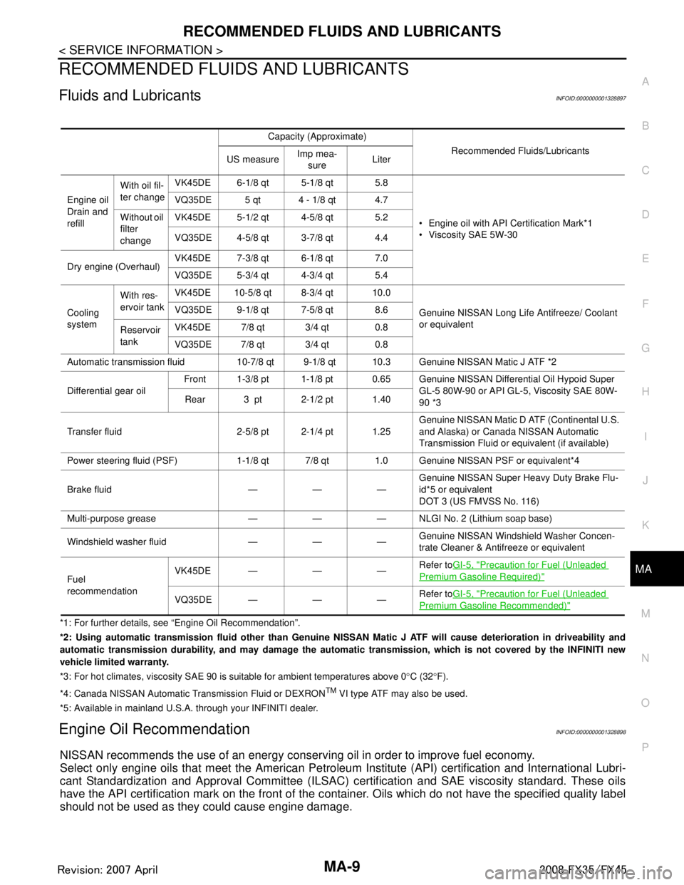
RECOMMENDED FLUIDS AND LUBRICANTS
Fluids and LubricantsINFOID:0000000001328897
*1: For further details, see “Engine Oil Recommendation”.
*2: Using automatic transmission fluid other than Genuine NISSAN Matic J ATF will cause deterioration in driveability and
automatic transmission durability, and may damage the automatic transmission, which is not covered by the INFINITI new
vehicle limited warranty.
*3: For hot climates, viscosity SAE 90 is suitable for ambient temperatures above 0 °C (32 °F).
*4: Canada NISSAN Au tomatic Transmission Fluid or DEXRON
TM VI type ATF may also be used.
*5: Available in mainland U.S.A. through your INFINITI dealer.
Engine Oil RecommendationINFOID:0000000001328898
NISSAN recommends the use of an energy conser ving oil in order to improve fuel economy.
Select only engine oils that meet the American Petroleum Institute (API) certification and International Lubri-
cant Standardization and Approval Committee (ILSAC) certification and SAE viscosity standard. These oils
have the API certification mark on the front of the c ontainer. Oils which do not have the specified quality label
should not be used as they could cause engine damage.
Capacity (Approximate)
Recommended Fluids/Lubricants
US measure Imp mea-
sure Liter
Engine oil
Drain and
refill With oil fil-
ter change
VK45DE 6-1/8 qt 5-1/8 qt 5.8
Engine oil with API Certification Mark*1
Viscosity SAE 5W-30
VQ35DE 5 qt 4 - 1/8 qt 4.7
Without oil
filter
change VK45DE 5-1/2 qt 4-5/8 qt 5.2
VQ35DE 4-5/8 qt 3-7/8 qt 4.4
Dry engine (Overhaul) VK45DE 7-3/8 qt 6-1/8 qt 7.0
VQ35DE 5-3/4 qt 4-3/4 qt 5.4
Cooling
system With res-
ervoir tank
VK45DE 10-5/8 qt 8-3/4 qt 10.0
Genuine NISSAN Long Life Antifreeze/ Coolant
or equivalent
VQ35DE 9-1/8 qt 7-5/8 qt 8.6
Reservoir
tank VK45DE 7/8 qt 3/4 qt 0.8
VQ35DE 7/8 qt 3/4 qt 0.8
Automatic transmission fluid 10-7/8 qt 9-1/8 qt 10.3 Genuine NISSAN Matic J ATF *2
Differential gear oil Front 1-3/8 pt 1-1/8 pt 0.65 Genuine NI
SSAN Differential Oil Hypoid Super
GL-5 80W-90 or API GL-5, Viscosity SAE 80W-
90 *3
Rear 3 pt 2-1/2 pt 1.40
Transfer fluid 2-5/8 pt 2-1/4 pt 1.25 Genuine NISSAN Matic D ATF (Continental U.S.
and Alaska) or Canada NISSAN Automatic
Transmission Fluid or equivalent (if available)
Power steering fluid (PSF) 1-1/8 qt 7/8 qt 1.0 Genuine NISSAN PSF or equivalent*4
Brake fluid — — — Genuine NISSAN Super He
avy Duty Brake Flu-
id*5 or equivalent
DOT 3 (US FMVSS No. 116)
Multi-purpose grease — — — NLGI No. 2 (Lithium soap base)
Windshield washer fluid — — — Genuine NISSAN Windshie
ld Washer Concen-
trate Cleaner & Antifreeze or equivalent
Fuel
recommendation VK45DE — — —
Refer to
GI-5, "
Precaution for Fuel (Unleaded
Premium Gasoline Required)"
VQ35DE——— Refer to
GI-5, "Precaution for Fuel (Unleaded
Premium Gasoline Recommended)"
3AA93ABC3ACD3AC03ACA3AC03AC63AC53A913A773A893A873A873A8E3A773A983AC73AC93AC03AC3
3A893A873A873A8F3A773A9D3AAF3A8A3A8C3A863A9D3AAF3A8B3A8C
Page 3462 of 3924
POWER STEERING FLUIDPS-7
< SERVICE INFORMATION >
C
DE
F
H I
J
K L
M A
B
PS
N
O P
POWER STEERING FLUID
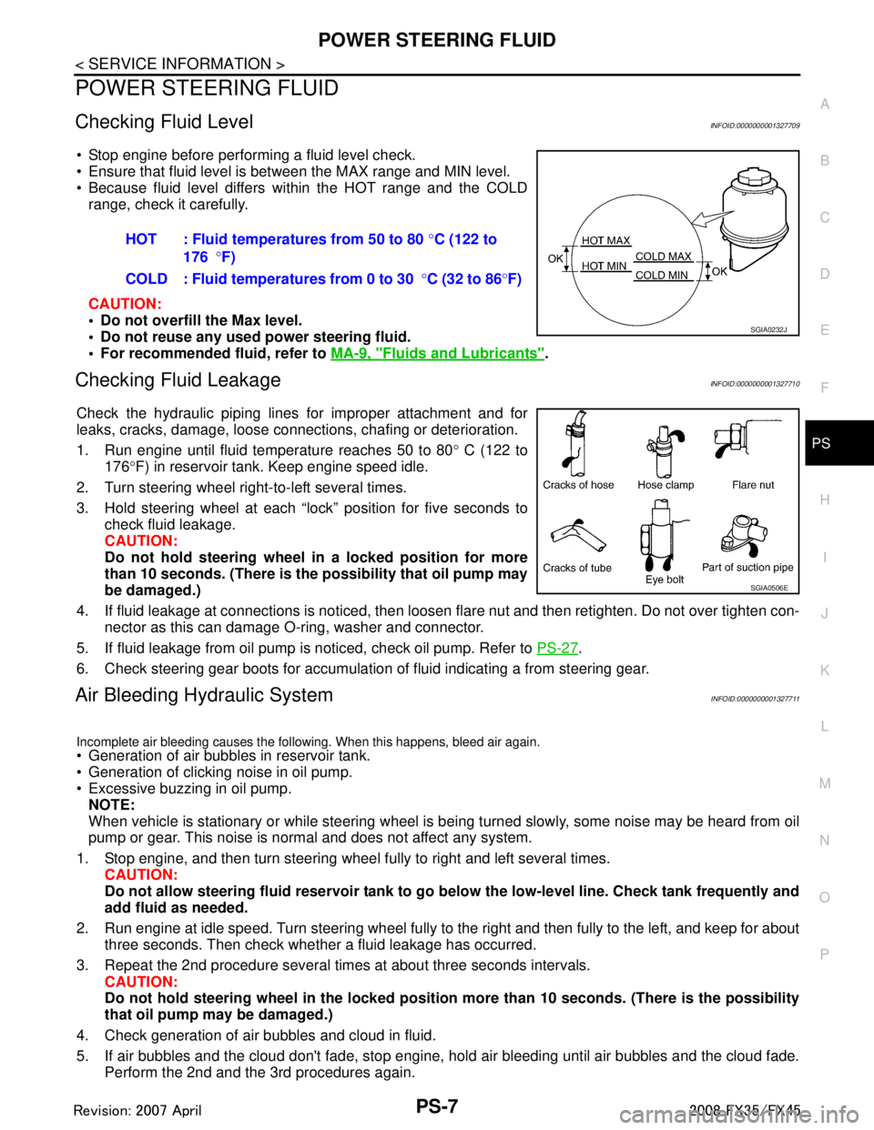
Checking Fluid LevelINFOID:0000000001327709
Stop engine before performing a fluid level check.
Ensure that fluid level is between the MAX range and MIN level.
Because fluid level differs within the HOT range and the COLD range, check it carefully.
CAUTION:
Do not overfill the Max level.
Do not reuse any used power steering fluid.
For recommended fluid, refer to MA-9, "
Fluids and Lubricants".
Checking Fluid LeakageINFOID:0000000001327710
Check the hydraulic piping lines for improper attachment and for
leaks, cracks, damage, loose connections, chafing or deterioration.
1. Run engine until fluid temperature reaches 50 to 80 ° C (122 to
176 °F) in reservoir tank. Keep engine speed idle.
2. Turn steering wheel right-to-left several times.
3. Hold steering wheel at each “lock” position for five seconds to check fluid leakage.
CAUTION:
Do not hold steering wheel in a locked position for more
than 10 seconds. (There is the possibility that oil pump may
be damaged.)
4. If fluid leakage at connections is noticed, then loos en flare nut and then retighten. Do not over tighten con-
nector as this can damage O-ring, washer and connector.
5. If fluid leakage from oil pump is noticed, check oil pump. Refer to PS-27
.
6. Check steering gear boots for accumulation of fluid indicating a from steering gear.
Air Bleeding Hydraulic SystemINFOID:0000000001327711
Incomplete air bleeding causes the following. When this happens, bleed air again.
Generation of air bubbles in reservoir tank.
Generation of clicking noise in oil pump.
Excessive buzzing in oil pump. NOTE:
When vehicle is stationary or while steering wheel is being turned slowly, some noise may be heard from oil
pump or gear. This noise is normal and does not affect any system.
1. Stop engine, and then turn steering wheel fully to right and left several times. CAUTION:
Do not allow steering fluid reservoir tank to go below the low-level line. Check tank frequently and
add fluid as needed.
2. Run engine at idle speed. Turn steering wheel fully to the right and then fully to the left, and keep for about
three seconds. Then check whether a fluid leakage has occurred.
3. Repeat the 2nd procedure several times at about three seconds intervals. CAUTION:
Do not hold steering wheel in the locked position more than 10 seconds. (There is the possibility
that oil pump may be damaged.)
4. Check generation of air bubbles and cloud in fluid.
5. If air bubbles and the cloud don't fade, stop engine, hold air bleeding until air bubbles and the cloud fade.
Perform the 2nd and the 3rd procedures again. HOT : Fluid temperatures from 50 to 80
°C (122 to
176 °F)
COLD : Fluid temperatures from 0 to 30 °C (32 to 86 °F)
SGIA0232J
SGIA0506E
3AA93ABC3ACD3AC03ACA3AC03AC63AC53A913A773A893A873A873A8E3A773A983AC73AC93AC03AC3
3A893A873A873A8F3A773A9D3AAF3A8A3A8C3A863A9D3AAF3A8B3A8C
Page 3478 of 3924
POWER STEERING GEAR AND LINKAGEPS-23
< SERVICE INFORMATION >
C
DE
F
H I
J
K L
M A
B
PS
N
O P
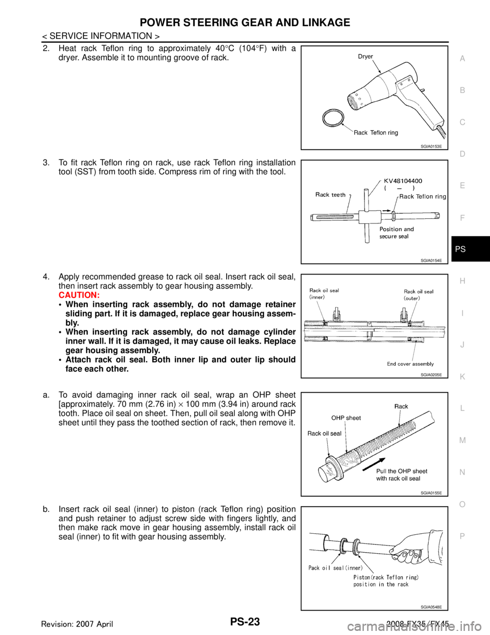
2. Heat rack Teflon ring to approximately 40 °C (104 °F) with a
dryer. Assemble it to mounting groove of rack.
3. To fit rack Teflon ring on rack, use rack Teflon ring installation tool (SST) from tooth side. Comp ress rim of ring with the tool.
4. Apply recommended grease to rack oil seal. Insert rack oil seal, then insert rack assembly to gear housing assembly.
CAUTION:
When inserting rack assembly, do not damage retainersliding part. If it is dama ged, replace gear housing assem-
bly.
When inserting rack assembly, do not damage cylinder
inner wall. If it is damaged, it may cause oil leaks. Replace
gear housing assembly.
Attach rack oil seal. Both in ner lip and outer lip should
face each other.
a. To avoid damaging inner rack oil seal, wrap an OHP sheet [approximately. 70 mm (2.76 in) × 100 mm (3.94 in) around rack
tooth. Place oil seal on sheet. Then, pull oil seal along with OHP
sheet until they pass the toothed se ction of rack, then remove it.
b. Insert rack oil seal (inner) to piston (rack Teflon ring) position and push retainer to adjust screw side with fingers lightly, and
then make rack move in gear housing assembly, install rack oil
seal (inner) to fit with gear housing assembly.
SGIA0153E
SGIA0154E
SGIA0205E
SGIA0155E
SGIA0548E
3AA93ABC3ACD3AC03ACA3AC03AC63AC53A913A773A893A873A873A8E3A773A983AC73AC93AC03AC3
3A893A873A873A8F3A773A9D3AAF3A8A3A8C3A863A9D3AAF3A8B3A8C
Page 3479 of 3924
![INFINITI FX35 2008 Service Manual
PS-24
< SERVICE INFORMATION >
POWER STEERING GEAR AND LINKAGE
c. When installing outer rack oil seal, cover the end of rack with anOHP sheet [70 mm (2.76 in) × 100 mm (3.94 in)]. It will avoid
dama INFINITI FX35 2008 Service Manual
PS-24
< SERVICE INFORMATION >
POWER STEERING GEAR AND LINKAGE
c. When installing outer rack oil seal, cover the end of rack with anOHP sheet [70 mm (2.76 in) × 100 mm (3.94 in)]. It will avoid
dama](/manual-img/42/57017/w960_57017-3478.png)
PS-24
< SERVICE INFORMATION >
POWER STEERING GEAR AND LINKAGE
c. When installing outer rack oil seal, cover the end of rack with anOHP sheet [70 mm (2.76 in) × 100 mm (3.94 in)]. It will avoid
damaging rack oil seal. Then place oil seal on sheet. Pull rack oil
seal along with OHP sheet until they pass rack end. Then
remove OHP sheet.
d. Install end cover assembly to rack, move it to gear housing assembly.
5. Using a 45 mm (1.77 in) open head (suitable tool), tighten end cover assembly at the specified torque.
CAUTION:
Do not damage rack surface. If it is damaged, it may cause
oil leaks. Replace rack assembly.
6. After tightening end cover assembly, caulk cylinder at one point as shown in the figure using a punch. This will prevent end cover
from getting loose.
7. Install pinion assembly to gear housing assembly. CAUTION:
In order to protect oil seal from any damage, insert pinion
assembly out straightly.
8. Apply recommended fluid to O-ring. Install O-ring to rear cover.
9. Use a rear cover wrench (SST), install rear cover to gear hous- ing assembly.
10. Confirm projection on rear cover cap nearly fit with marking posi- tion on gear housing assembly.
11. Apply recommended thread locking sealant to the thread (2 turns thread), and then screw in the adjusting screw until it
reaches height “H” from gear housing assembly measured
before disassembling.
12. Rotate pinion ten times whole range of rack so that parts get to fit with each other.
SGIA0157E
SST081B
SGIA0158E
SGIA0568E
3AA93ABC3ACD3AC03ACA3AC03AC63AC53A913A773A893A873A873A8E3A773A983AC73AC93AC03AC3
3A893A873A873A8F3A773A9D3AAF3A8A3A8C3A863A9D3AAF3A8B3A8C
Page 3486 of 3924
POWER STEERING OIL PUMPPS-31
< SERVICE INFORMATION >
C
DE
F
H I
J
K L
M A
B
PS
N
O P
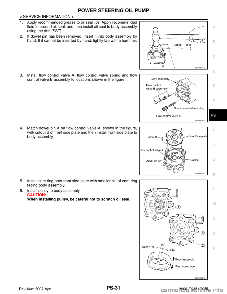
1. Apply recommended grease to oil seal lips. Apply recommended fluid to around oil seal, and then install oil seal to body assembly
using the drift [SST].
2. If dowel pin has been removed, insert it into body assembly by hand. If it cannot be inserted by hand, lightly tap with a hammer.
3. Install flow control valve A, flow control valve spring and flow control valve B assembly to locations shown in the figure.
4. Match dowel pin A on flow control valve A, shown in the figure, with cutout B of front side plate and then install front side plate to
body assembly.
5. Install cam ring onto front side pl ate with smaller slit of cam ring
facing body assembly.
6. Install pulley to body assembly. CAUTION:
When installing pulley, be car eful not to scratch oil seal.
SGIA0527E
SGIA0526E
SGIA0528E
SGIA0623E
3AA93ABC3ACD3AC03ACA3AC03AC63AC53A913A773A893A873A873A8E3A773A983AC73AC93AC03AC3
3A893A873A873A8F3A773A9D3AAF3A8A3A8C3A863A9D3AAF3A8B3A8C
Page 3487 of 3924
PS-32
< SERVICE INFORMATION >
POWER STEERING OIL PUMP
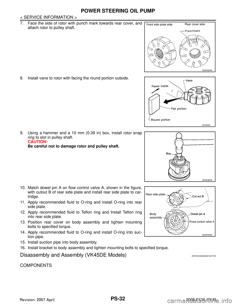
7. Face the side of rotor with punch mark towards rear cover, andattach rotor to pulley shaft.
8. Install vane to rotor with facing the round portion outside.
9. Using a hammer and a 10 mm (0.39 in) box, install rotor snap ring to slot in pulley shaft.
CAUTION:
Be careful not to damage rotor and pulley shaft.
10. Match dowel pin A on flow control valve A, shown in the figure, with cutout B of rear side plate and install rear side plate to car-
tridge.
11. Apply recommended fluid to O-ring and install O-ring into rear side plate.
12. Apply recommended fluid to Teflon ring and Install Teflon ring into rear side plate.
13. Position rear cover on body assembly and tighten mounting bolts to specified torque.
14. Apply recommended fluid to O-ring and install O-ring into suc- tion pipe.
15. Install suction pipe into body assembly.
16. Install bracket to body assembly and tighten mounting bolts to specified torque.
Disassembly and Assemb ly (VK45DE Models)INFOID:0000000001327722
COMPONENTS
SGIA0529E
SST843A
SGIA0063E
SGIA0530E
3AA93ABC3ACD3AC03ACA3AC03AC63AC53A913A773A893A873A873A8E3A773A983AC73AC93AC03AC3
3A893A873A873A8F3A773A9D3AAF3A8A3A8C3A863A9D3AAF3A8B3A8C
Page 3490 of 3924
POWER STEERING OIL PUMPPS-35
< SERVICE INFORMATION >
C
DE
F
H I
J
K L
M A
B
PS
N
O P
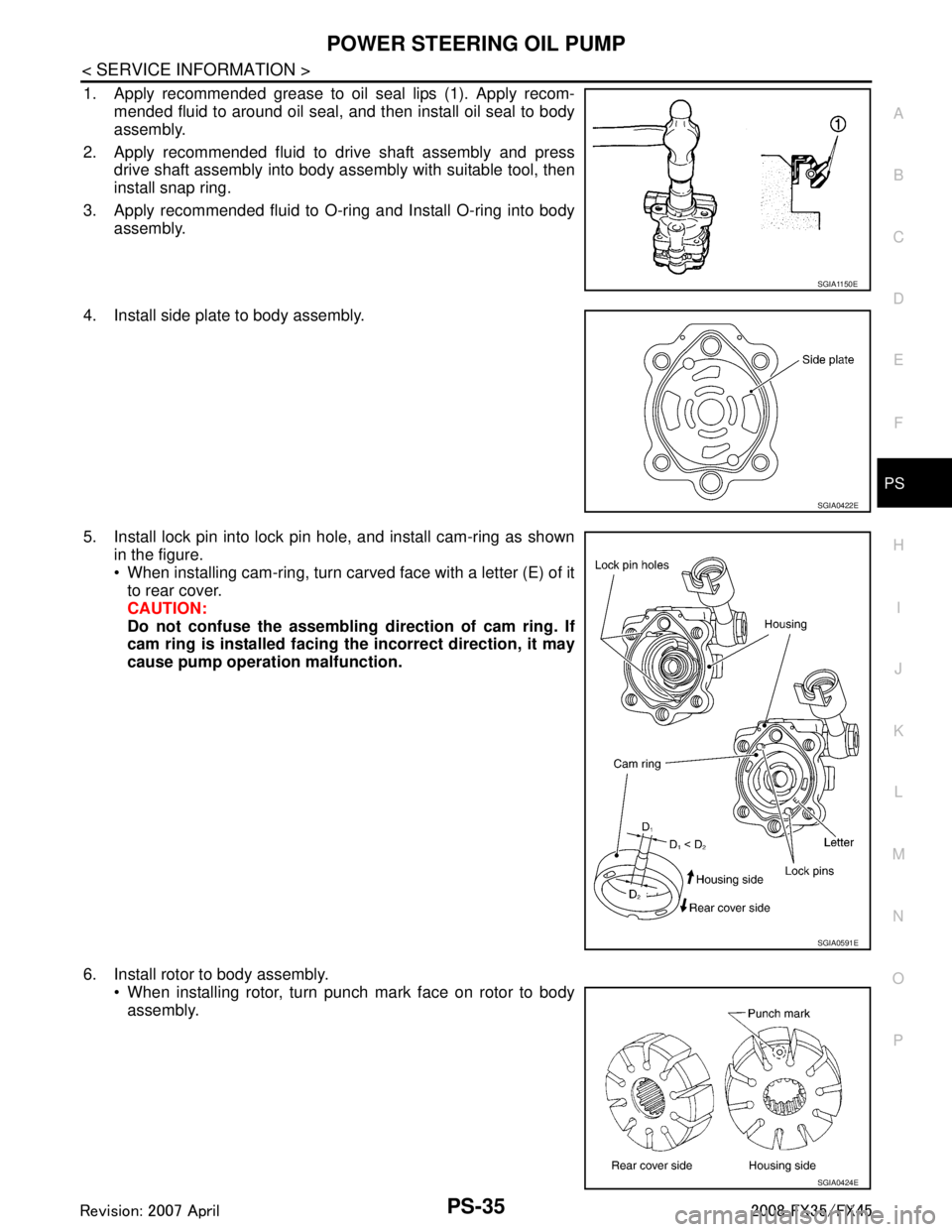
1. Apply recommended grease to oil seal lips (1). Apply recom- mended fluid to around oil seal, and then install oil seal to body
assembly.
2. Apply recommended fluid to drive shaft assembly and press drive shaft assembly into body assembly with suitable tool, then
install snap ring.
3. Apply recommended fluid to O-ring and Install O-ring into body assembly.
4. Install side plate to body assembly.
5. Install lock pin into lock pin hole, and install cam-ring as shown in the figure.
When installing cam-ring, turn carved face with a letter (E) of itto rear cover.
CAUTION:
Do not confuse the assembling direction of cam ring. If
cam ring is installed facing th e incorrect direction, it may
cause pump operation malfunction.
6. Install rotor to body assembly. When installing rotor, turn punch mark face on rotor to bodyassembly.
SGIA1150E
SGIA0422E
SGIA0591E
SGIA0424E
3AA93ABC3ACD3AC03ACA3AC03AC63AC53A913A773A893A873A873A8E3A773A983AC73AC93AC03AC3
3A893A873A873A8F3A773A9D3AAF3A8A3A8C3A863A9D3AAF3A8B3A8C
Page 3491 of 3924
PS-36
< SERVICE INFORMATION >
POWER STEERING OIL PUMP
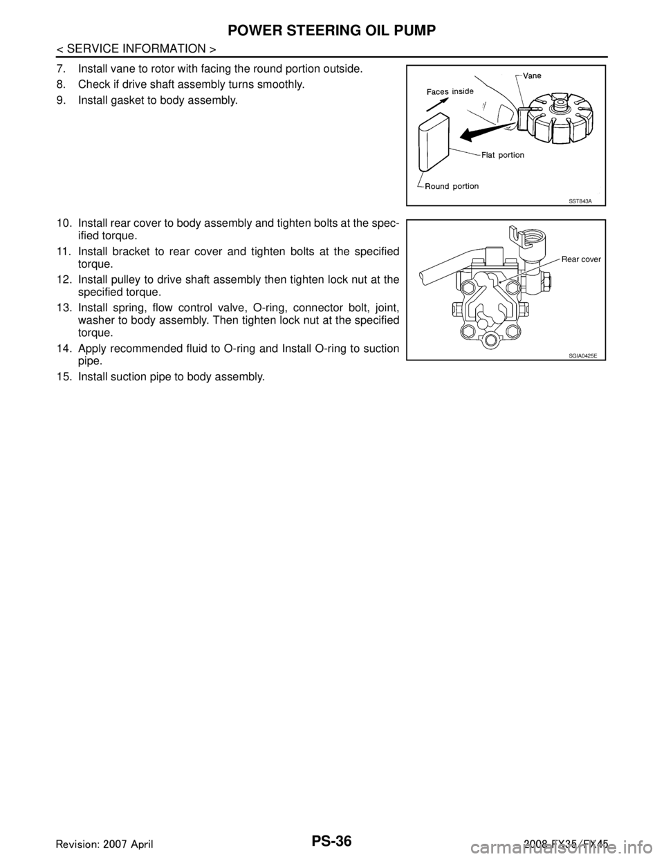
7. Install vane to rotor with facing the round portion outside.
8. Check if drive shaft assembly turns smoothly.
9. Install gasket to body assembly.
10. Install rear cover to body assembly and tighten bolts at the spec-ified torque.
11. Install bracket to rear cover and tighten bolts at the specified torque.
12. Install pulley to drive shaft assembly then tighten lock nut at the specified torque.
13. Install spring, flow control valve, O-ring, connector bolt, joint, washer to body assembly. Then tighten lock nut at the specified
torque.
14. Apply recommended fluid to O-ring and Install O-ring to suction pipe.
15. Install suction pipe to body assembly.
SST843A
SGIA0425E
3AA93ABC3ACD3AC03ACA3AC03AC63AC53A913A773A893A873A873A8E3A773A983AC73AC93AC03AC3
3A893A873A873A8F3A773A9D3AAF3A8A3A8C3A863A9D3AAF3A8B3A8C