2008 INFINITI FX35 recommended oil
[x] Cancel search: recommended oilPage 2863 of 3924
GI-1
GENERAL INFORMATION
C
DE
F
G H
I
J
K L
M B
GI
SECTION GI
N
O P
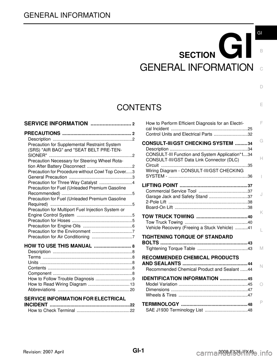
CONTENTS
GENERAL INFORMATION
SERVICE INFORMATION .. ..........................2
PRECAUTIONS .............................................. .....2
Description .......................................................... ......2
Precaution for Supplemental Restraint System
(SRS) "AIR BAG" and "SEAT BELT PRE-TEN-
SIONER" ...................................................................
2
Precaution Necessary for Steering Wheel Rota-
tion After Battery Disconnect .....................................
2
Precaution for Procedure without Cowl Top Cover ......3
General Precaution ...................................................3
Precaution for Three Way Catalyst ...........................4
Precaution for Fuel (Unleaded Premium Gasoline
Recommended) .........................................................
5
Precaution for Fuel (Unleaded Premium Gasoline
Required) ..................................................................
5
Precaution for Multiport Fuel Injection System or
Engine Control System .............................................
5
Precaution for Hoses .................................................5
Precaution for Engine Oils ........................................6
Precaution for the Environment .................................7
Precaution for Air Conditioning .................................7
HOW TO USE THIS MANUAL ............................8
Description .......................................................... ......8
Terms ........................................................................8
Units ..........................................................................8
Contents ....................................................................8
Component ................................................................8
How to Follow Trouble Diagnosis ..............................9
How to Read Wiring Diagram ..................................13
Abbreviations ..........................................................20
SERVICE INFORMATION FOR ELECTRICAL
INCIDENT ...........................................................
22
How to Check Terminal ....................................... ....22
How to Perform Efficient Diagnosis for an Electri-
cal Incident .......................................................... ....
25
Control Units and Electrical Parts ............................32
CONSULT-III/GST CHECKING SYSTEM .........34
Description ...............................................................34
CONSULT-III Function and System Application*1 ....34
CONSULT-III/GST Data Link Connector (DLC)
Circuit ......................................................................
35
Wiring Diagram - CONSULT-III/GST CHECKING
SYSTEM - ................................................................
36
LIFTING POINT .................................................37
Commercial Service Tool ........................................37
Garage Jack and Safety Stand ................................37
2-Pole Lift ................................................................38
Board-On Lift ...........................................................38
TOW TRUCK TOWING .....................................40
Tow Truck Towing ...................................................40
Vehicle Recovery (Freeing a Stuck Vehicle) ...........41
TIGHTENING TORQUE OF STANDARD
BOLTS ...............................................................
43
Tightening Torque Table .........................................43
RECOMMENDED CHEMICAL PRODUCTS
AND SEALANTS ...............................................
44
Recommended Chemical Product and Sealant .......44
IDENTIFICATION INFORMATION ....................45
Model Variation ........................................................45
Dimensions ..............................................................47
Wheels & Tires ........................................................47
TERMINOLOGY ................................................48
SAE J1930 Terminology List ...................................48
3AA93ABC3ACD3AC03ACA3AC03AC63AC53A913A773A893A873A873A8E3A773A983AC73AC93AC03AC3
3A893A873A873A8F3A773A9D3AAF3A8A3A8C3A863A9D3AAF3A8B3A8C
Page 2866 of 3924
GI-4
< SERVICE INFORMATION >
PRECAUTIONS
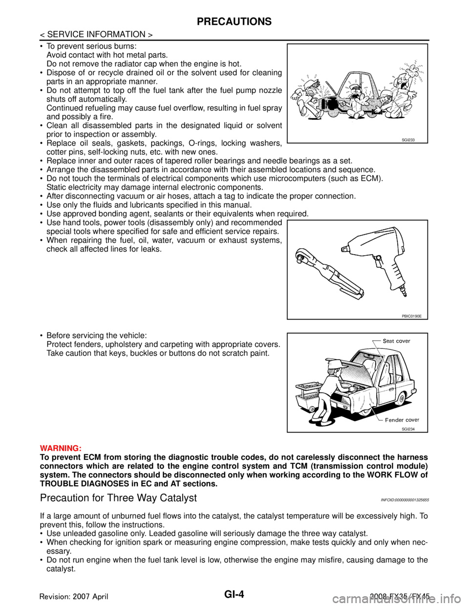
To prevent serious burns:Avoid contact with hot metal parts.
Do not remove the radiator cap when the engine is hot.
Dispose of or recycle drained oil or the solvent used for cleaning parts in an appropriate manner.
Do not attempt to top off the fuel tank after the fuel pump nozzle
shuts off automatically.
Continued refueling may cause fuel overflow, resulting in fuel spray
and possibly a fire.
Clean all disassembled parts in the designated liquid or solvent prior to inspection or assembly.
Replace oil seals, gaskets, packings, O-rings, locking washers, cotter pins, self-locking nuts, etc. with new ones.
Replace inner and outer races of tapered roller bearings and needle bearings as a set.
Arrange the disassembled parts in accordance with their assembled locations and sequence.
Do not touch the terminals of electrical com ponents which use microcomputers (such as ECM).
Static electricity may damage internal electronic components.
After disconnecting vacuum or air hoses, atta ch a tag to indicate the proper connection.
Use only the fluids and lubricants specified in this manual.
Use approved bonding agent, sealants or their equivalents when required.
Use hand tools, power tools (disassembly only) and recommended special tools where specified for safe and efficient service repairs.
When repairing the fuel, oil, water, vacuum or exhaust systems,
check all affected lines for leaks.
Before servicing the vehicle: Protect fenders, upholstery and carpeting with appropriate covers.
Take caution that keys, buckles or buttons do not scratch paint.
WARNING:
To prevent ECM from storing the diagnostic tro uble codes, do not carelessly disconnect the harness
connectors which are related to the engine cont rol system and TCM (transmission control module)
system. The connectors should be disconnected on ly when working according to the WORK FLOW of
TROUBLE DIAGNOSES in EC and AT sections.
Precaution for Three Way CatalystINFOID:0000000001325655
If a large amount of unburned fuel flows into the catalyst , the catalyst temperature will be excessively high. To
prevent this, follow the instructions.
Use unleaded gasoline only. Leaded gasoline will seriously damage the three way catalyst.
When checking for ignition spark or measuring engine compression, make tests quickly and only when nec- essary.
Do not run engine when the fuel tank level is low, otherwise the engine may misfire, causing damage to the
catalyst.
SGI233
PBIC0190E
SGI234
3AA93ABC3ACD3AC03ACA3AC03AC63AC53A913A773A893A873A873A8E3A773A983AC73AC93AC03AC3
3A893A873A873A8F3A773A9D3AAF3A8A3A8C3A863A9D3AAF3A8B3A8C
Page 3291 of 3924
![INFINITI FX35 2008 Service Manual
LU-6
< SERVICE INFORMATION >[VQ35DE]
ENGINE OIL
WARNING:
• Be careful not to get burn your
self, as engine oil may be hot.
Oil pressure check should be done in “Parking position”.
1. Check t INFINITI FX35 2008 Service Manual
LU-6
< SERVICE INFORMATION >[VQ35DE]
ENGINE OIL
WARNING:
• Be careful not to get burn your
self, as engine oil may be hot.
Oil pressure check should be done in “Parking position”.
1. Check t](/manual-img/42/57017/w960_57017-3290.png)
LU-6
< SERVICE INFORMATION >[VQ35DE]
ENGINE OIL
WARNING:
• Be careful not to get burn your
self, as engine oil may be hot.
Oil pressure check should be done in “Parking position”.
1. Check the engine oil level. Refer to "ENGINE OIL LEVEL".
2. Remove front engine undercover with power tool.
3. Disconnect harness connector at oil pressure sensor, and remove oil pressure sensor using deep socket (commercial ser-
vice tool).
CAUTION:
Do not drop or shock oil pressure switch.
4. Install the oil pressure gauge (SST) and hose (SST).
5. Start the engine and warm it up to normal operating temperature.
6. Check the engine oil pressure with engine running under no-load. NOTE:
When the engine oil temperature is low, the engine oil pressure becomes high.
Engine oil pressure [Engi ne oil temperature at 80 °C (176 °F)]
Unit: kPa (kg/cm2, psi)
If difference is extreme, check engine oil passage and oil pump for engine oil leaks.
7. After the inspections, install oil pressure switch as follows:
a. Remove old liquid gasket adhering to oil pressure switch and the mating surface.
b. Apply liquid gasket and tighten oil pressure switch to the specification. Use Genuine RTV Silicone Seal ant or equivalent. Refer to GI-44, "
Recommended Chemical Prod-
uct and Sealant".
SBIA0452E
SBIA0453E
SLC926
Engine speed Approximate discharge pressure
Idle speed More than 98 (1.0, 14)2,000 rpm More than 294 (3.0, 43)
3AA93ABC3ACD3AC03ACA3AC03AC63AC53A913A773A893A873A873A8E3A773A983AC73AC93AC03AC3
3A893A873A873A8F3A773A9D3AAF3A8A3A8C3A863A9D3AAF3A8B3A8C
Page 3295 of 3924
![INFINITI FX35 2008 Service Manual
LU-10
< SERVICE INFORMATION >[VQ35DE]
OIL FILTER BRACKET (AWD)
OIL FILTER BRACKET (AWD)
ComponentINFOID:0000000001325816
Removal and InstallationINFOID:0000000001325817
REMOVAL
WARNING:
Be careful no INFINITI FX35 2008 Service Manual
LU-10
< SERVICE INFORMATION >[VQ35DE]
OIL FILTER BRACKET (AWD)
OIL FILTER BRACKET (AWD)
ComponentINFOID:0000000001325816
Removal and InstallationINFOID:0000000001325817
REMOVAL
WARNING:
Be careful no](/manual-img/42/57017/w960_57017-3294.png)
LU-10
< SERVICE INFORMATION >[VQ35DE]
OIL FILTER BRACKET (AWD)
OIL FILTER BRACKET (AWD)
ComponentINFOID:0000000001325816
Removal and InstallationINFOID:0000000001325817
REMOVAL
WARNING:
Be careful not to get burn yourself, as engine oil may be hot.
1. Remove front engine undercover with power tool.
2. Using the oil filter wrench [SST: KV10115801 (J38956)], remove oil filter. Refer to
LU-8, "
Removal and
Installation".
CAUTION:
Do not spill engine oil on drive belt.
3. Remove oil cooler connector bolt, and then oil cooler with water hoses connected.
4. Disconnect oil temperature sensor and oi l pressure switch harness connectors.
5. Remove oil filter bracket from oil pan (upper).
6. Remove oil temperature sensor and oil pr essure switch from oil filter bracket.
INSTALLATION
Note the following, and install in the reverse order of removal.
Install oil pressure switch and oil temperature sensor as follows:
- Remove old liquid gasket adhering to oil pressure switch and oil filter bracket.
- Apply liquid gasket and install oil pressure switch, and then oil temperature sensor with a new washer.
Use Genuine RTV Silicone Seal ant or equivalent. Refer to GI-44, "
Recommended Chemical Product
and Sealant".
1. Oil filter 2. Connector bolt 3. Oil cooler
4. O-ring 5. Relief valve 6. Oil filter bracket
7. Gasket 8. Oil pressure switch 9. Oil temperature sensor
10. Washer 11. Oil pan (upper)
SBIA0593E
3AA93ABC3ACD3AC03ACA3AC03AC63AC53A913A773A893A873A873A8E3A773A983AC73AC93AC03AC3
3A893A873A873A8F3A773A9D3AAF3A8A3A8C3A863A9D3AAF3A8B3A8C
Page 3309 of 3924
![INFINITI FX35 2008 Service Manual
LU-24
< SERVICE INFORMATION >[VK45DE]
ENGINE OIL
4. Install oil pressure gauge and hose (SST).
5. Start engine and warm it up to normal operating temperature.
6. Check the engine oil pressure with en INFINITI FX35 2008 Service Manual
LU-24
< SERVICE INFORMATION >[VK45DE]
ENGINE OIL
4. Install oil pressure gauge and hose (SST).
5. Start engine and warm it up to normal operating temperature.
6. Check the engine oil pressure with en](/manual-img/42/57017/w960_57017-3308.png)
LU-24
< SERVICE INFORMATION >[VK45DE]
ENGINE OIL
4. Install oil pressure gauge and hose (SST).
5. Start engine and warm it up to normal operating temperature.
6. Check the engine oil pressure with engine running under no-load.
NOTE:
When engine oil temperature is low, engine oil pressure becomes high.
Engine oil pressure [Eng ine oil temperature at 80°C (176 °F)]
Uni t: kPa (kg/cm2, psi)
If difference is extreme, check oil passage and oil pump for oil leaks.
7. After the inspections, install oil pressure switch as follows:
a. Remove old liquid gasket adhering to oil presser switch and engine.
b. Apply liquid gasket and tighten oil pressure switch to the specification. Use Genuine RTV Silicone Seal ant or equivalent. Refer to GI-44, "
Recommended Chemical Prod-
uct and Sealant".
c. After warming up engine, make sure there is no leakage of engine oil with running engine.
Changing Engine OilINFOID:0000000001325830
WARNING:
Be careful not to burn yoursel f, as engine oil may be hot.
Prolonged and repeated contact with used engine oil may cause ski n cancer. Try to avoid direct skin
contact with used engine oil. If skin contact is made, wash thoroughly with soap or hand cleaner as
soon as possible.
1. Remove front engine undercover with power tool.
2. Warm up engine, put vehicle horizontally and check for engine oil leakage from engine components. Refer
to LU-23, "
Inspection".
3. Stop engine and wait for 15 minutes.
4. Loosen oil filler cap, and then remove drain plug.
5. Drain engine oil.
SLC926
Engine speed Approximate discharge pressure
Idle speed More than 98 (1.0, 14)2,000 rpm More than 294 (3.0, 43)
: 14.8 N·m (1.5 kg-m, 11 ft-lb)
PBIC0993E
3AA93ABC3ACD3AC03ACA3AC03AC63AC53A913A773A893A873A873A8E3A773A983AC73AC93AC03AC3
3A893A873A873A8F3A773A9D3AAF3A8A3A8C3A863A9D3AAF3A8B3A8C
Page 3318 of 3924
MA-1
MAINTENANCE
C
DE
F
G H
I
J
K
M
SECTION MA
A
B
MA
N
O P
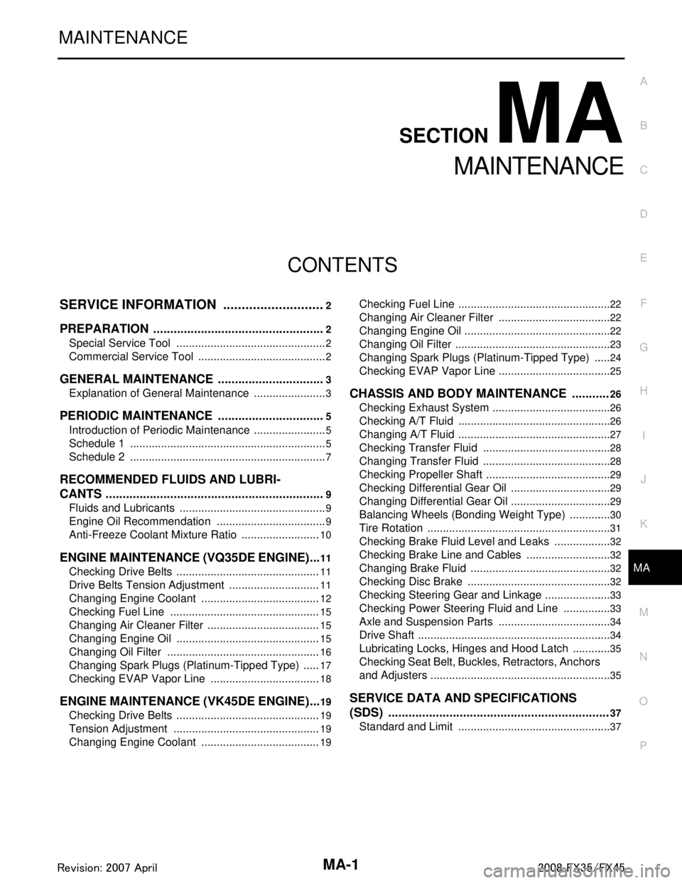
CONTENTS
MAINTENANCE
SERVICE INFORMATION .. ..........................2
PREPARATION .............................................. .....2
Special Service Tool ........................................... ......2
Commercial Service Tool ..........................................2
GENERAL MAINTENANCE ................................3
Explanation of General Maintenance .................. ......3
PERIODIC MAINTENANCE ................................5
Introduction of Periodic Maintenance .................. ......5
Schedule 1 ................................................................5
Schedule 2 ................................................................7
RECOMMENDED FLUIDS AND LUBRI-
CANTS .................................................................
9
Fluids and Lubricants .......................................... ......9
Engine Oil Recommendation ....................................9
Anti-Freeze Coolant Mixture Ratio ..........................10
ENGINE MAINTENANCE (VQ35DE ENGINE) ....11
Checking Drive Belts ........................................... ....11
Drive Belts Tension Adjustment ..............................11
Changing Engine Coolant .......................................12
Checking Fuel Line .................................................15
Changing Air Cleaner Filter .....................................15
Changing Engine Oil ...............................................15
Changing Oil Filter ..................................................16
Changing Spark Plugs (Platinum-Tipped Type) ......17
Checking EVAP Vapor Line ....................................18
ENGINE MAINTENANCE (VK45DE ENGINE) ....19
Checking Drive Belts ........................................... ....19
Tension Adjustment ................................................19
Changing Engine Coolant .......................................19
Checking Fuel Line .............................................. ....22
Changing Air Cleaner Filter .....................................22
Changing Engine Oil ................................................22
Changing Oil Filter ...................................................23
Changing Spark Plugs (Platinum-Tipped Type) ......24
Checking EVAP Vapor Line .....................................25
CHASSIS AND BODY MAINTENANCE ...........26
Checking Exhaust System ................................... ....26
Checking A/T Fluid ..................................................26
Changing A/T Fluid ..................................................27
Checking Transfer Fluid ..........................................28
Changing Transfer Fluid ..........................................28
Checking Propeller Shaft .........................................29
Checking Differential Gear Oil .................................29
Changing Differential Gear Oil .................................29
Balancing Wheels (Bonding Weight Type) ..............30
Tire Rotation ............................................................31
Checking Brake Fluid Level and Leaks ...................32
Checking Brake Line and Cables ............................32
Changing Brake Fluid ..............................................32
Checking Disc Brake ...............................................32
Checking Steering Gear and Linkage ......................33
Checking Power Steering Fluid and Line ................33
Axle and Suspension Parts .....................................34
Drive Shaft ...............................................................34
Lubricating Locks, Hinges and Hood Latch .............35
Checking Seat Belt, Buckles, Retractors, Anchors
and Adjusters ...........................................................
35
SERVICE DATA AND SPECIFICATIONS
(SDS) .................................................................
37
Standard and Limit ..................................................37
3AA93ABC3ACD3AC03ACA3AC03AC63AC53A913A773A893A873A873A8E3A773A983AC73AC93AC03AC3
3A893A873A873A8F3A773A9D3AAF3A8A3A8C3A863A9D3AAF3A8B3A8C
Page 3323 of 3924
MA-6
< SERVICE INFORMATION >
PERIODIC MAINTENANCE
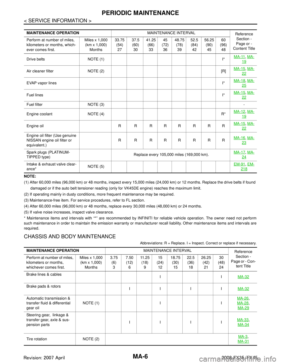
NOTE:
(1) After 60,000 miles (96,000 km) or 48 months, inspect every 15,000 miles (24,000 km) or 12 months. Replace the drive belts if found
damaged or if the auto belt tensioner reading (only for VK45DE engine) reaches the maximum limit.
(2) If operating mainly in dusty conditions, more frequent maintenance may be required.
(3) Maintenance-free item. For service procedures, refer to FL section.
(4) After 60,000 miles (96,000 km) or 48 months, replace every 30,000 miles (48,000 km) or 24 months.
(5) If valve noise increases, inspect valve clearance.
* Maintenance items and intervals with “*” are recommended by INFINITI for reliable vehicle operation. The owner need not perfo rm
such maintenance in order to maintain the emission warranty or manufacturer recall liability. Other maintenance items and inter vals are
required.
CHASSIS AND BODY MAINTENANCE
Abbreviations: R = Replace. I = Inspec t. Correct or replace if necessary.
MAINTENANCE OPERATION MAINTENANCE INTERVAL
Reference
Section -
Page or -
Content Title
Perform at number of miles,
kilometers or months, which-
ever comes first. Miles x 1,000
(km x 1,000) Months 33.75
(54)27 37.5
(60) 30 41.25
(66)33 45
(72) 36 48.75
(78)39 52.5
(84) 42 56.25
(90)45 60
(96) 48
Drive belts NOTE (1) I* MA-11
,
MA-
19
Air cleaner filter NOTE (2) [R] MA-15,
MA-
22
EVAP vapor lines I*MA-18,
MA-
25
Fuel lines I*MA-15,
MA-
22
Fuel filter NOTE (3) -
Engine coolant NOTE (4) R* MA-12
,
MA-
19
Engine oil R R R R R R R R MA-15,
MA-
22
Engine oil filter (Use genuine
NISSAN engine oil filter or
equivalent.) R R RRRRRR
MA-16,
MA-
23
Spark plugs (PLATINUM-
TIPPED type) Replace every 105,000 miles (169,000 km).MA-17,
MA-
24
Intake & exhaust valve clear-
ance* NOTE (5) EM-91,
EM-
218
MAINTENANCE OPERATION MAINTENANCE INTERVAL
Reference
Section -
Page or - Con-
tent Title
Perform at number of miles,
kilometers or months,
whichever comes first. Miles x 1,000
(km x 1,000) Months 3.75
(6)3 7.50
(12) 6 11 . 2 5
(18) 9 15
(24) 12 18.75
(30)15 22.5
(36) 18 26.25
(42)21 30
(48) 24
Brake lines & cables IIMA-32
Brake pads & rotors
IIII MA-32
Automatic transmission &
transfer fluid & differential
gear oilNOTE (1) I I MA-26,
MA-28
,
MA-29
Steering gear, linkage &
transfer gear, axle & sus-
pension parts IIII
MA-33
,
MA-34
Tire rotation NOTE (2) MA-3,
MA-31
3AA93ABC3ACD3AC03ACA3AC03AC63AC53A913A773A893A873A873A8E3A773A983AC73AC93AC03AC3
3A893A873A873A8F3A773A9D3AAF3A8A3A8C3A863A9D3AAF3A8B3A8C
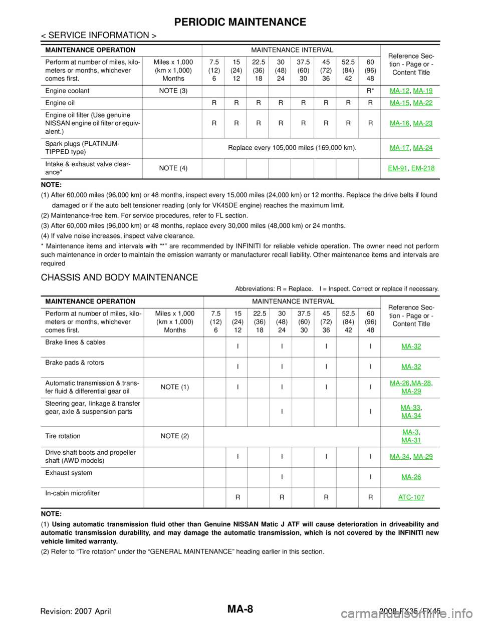
Page 3325 of 3924
MA-8
< SERVICE INFORMATION >
PERIODIC MAINTENANCE
NOTE:
(1) After 60,000 miles (96,000 km) or 48 months, inspect every 15,000 miles (24,000 km) or 12 months. Replace the drive belts if found
damaged or if the auto belt tensioner reading (only for VK45DE engine) reaches the maximum limit.
(2) Maintenance-free item. For service procedures, refer to FL section.
(3) After 60,000 miles (96,000 km) or 48 months, replace every 30,000 miles (48,000 km) or 24 months.
(4) If valve noise increases, inspect valve clearance.
* Maintenance items and intervals with “*” are recommended by INFINITI for reliable vehicle operation. The owner need not perfo rm
such maintenance in order to maintain the emission warranty or manufacturer recall liability. Other maintenance items and inter vals are
required
CHASSIS AND BODY MAINTENANCE
Abbreviations: R = Replace. I = Inspec t. Correct or replace if necessary.
NOTE:
(1) Using automatic transmission fluid other than Genuine NISSAN Matic J ATF will cause deterioration in driveability and
automatic transmission durability, and may damage the automatic transmission, which is not covered by the INFINITI new
vehicle limited warranty.
(2) Refer to “Tire rotation” under the “GENERAL MAINTENANCE” heading earlier in this section.
Engine coolant NOTE (3) R*
MA-12
, MA-19
Engine oil R R R R R R R R MA-15, MA-22
Engine oil filter (Use genuine
NISSAN engine oil filter or equiv-
alent.) RRRR R RRR
MA-16
, MA-23
Spark plugs (PLATINUM-
TIPPED type) Replace every 105,000 miles (169,000 km).
MA-17, MA-24
Intake & exhaust valve clear-
ance* NOTE (4)
EM-91, EM-218
MAINTENANCE OPERATION MAINTENANCE INTERVAL
Reference Sec-
tion - Page or -
Content Title
Perform at number of miles, kilo-
meters or months, whichever
comes first. Miles x 1,000
(km x 1,000)
Months 7.5
(12)
6 15
(24)
12 22.5
(36)
18 30
(48)
24 37.5
(60)
30 45
(72)
36 52.5
(84)
42 60
(96)
48
MAINTENANCE OPERATION MAINTENANCE INTERVAL
Reference Sec-
tion - Page or - Content Title
Perform at number of miles, kilo-
meters or months, whichever
comes first. Miles x 1,000
(km x 1,000) Months 7.5
(12) 6 15
(24) 12 22.5
(36) 18 30
(48) 24 37.5
(60) 30 45
(72) 36 52.5
(84) 42 60
(96) 48
Brake lines & cables IIIIMA-32
Brake pads & rotors
IIIIMA-32
Automatic transmission & trans-
fer fluid & differential gear oilNOTE (1) IIII MA-26,
MA-28,
MA-29
Steering gear, linkage & transfer
gear, axle & suspension parts I I MA-33,
MA-34
Tire rotation NOTE (2) MA-3,
MA-31
Drive shaft boots and propeller
shaft (AWD models) IIII
MA-34, MA-29
Exhaust system
IIMA-26
In-cabin microfilter
RRRRAT C - 1 0 7
3AA93ABC3ACD3AC03ACA3AC03AC63AC53A913A773A893A873A873A8E3A773A983AC73AC93AC03AC3
3A893A873A873A8F3A773A9D3AAF3A8A3A8C3A863A9D3AAF3A8B3A8C