2008 INFINITI FX35 engine oil
[x] Cancel search: engine oilPage 1152 of 3924

DI-26
< SERVICE INFORMATION >
UNIFIED METER AND A/C AMP
UNIFIED METER AND A/C AMP
System DescriptionINFOID:0000000001328456
For the unified meter and A/C amp., the signal required for controlling the combination meter are integrated
in the A/C auto amp.
The unified meter and A/C amp. corresponds to a CONS ULT-III function (self-diagnosis results, CAN diag-
nosis support monitor, data monitor).
COMBINATION METER CONTROL FUNCTION
Unified meter and A/C amp. receives necessary information for combination meter from each unit by CAN communication.
Unified meter and A/C amp. transmits a signals with communication line (TX, RX) between unified meter and A/C amp. and combination meter.
Input/output signals between unified meter and A/C amp. and combination meter.
NOTE:
Combination meter performs fail-safe operation when unified meter and A/C amp. communication is malfunctioning. Refer to DI-5, "
Sys-
tem Description".
A/C AUTO AMP. FUNCTION
Unified meter and A/C amp. controls each operation for A/C auto amp. Regarding A/C control, refer to AT C -
24, "Description of Air Conditioner LAN Control System" in ATC section.
OTHER FUNCTIONS
Drive Computer Function
The signals required for the distance to empty (DTE) display are centralized in the unified meter and A/C
amp., converted into data, and transmitted to the disp lay unit (without NAVI) and display control unit (with
NAVI) using CAN communication.
Signal Buffer Function
Unified meter and A/C amp. transmits each signal to other units with CAN communication.
Unit Input Output
Unified meter and A/C amp. Seat belt buckle switch signal (Driver's side)
Parking brake signal
Illumination control nighttime required signal
Refuel status signal
Low-fuel warning lamp condition signal
Combination meter receive error signal
Delivery destination data signal
Combination meter specifications signal Vehicle speed signal (8-pulse)
Engine speed signal
Engine coolant temperature signal
Fuel level sensor signal (resistance value)
Malfunction indicator lamp signal
ABS warning lamp signal
Low tire pressure warning lamp signal
Run-flat tire wa
rning lamp signal
Brake warning lamp signal
A/T CHECK warning lamp signal
ICC warning lamp signal
Oil pressure switch signal
Door switch signal
AWD warning lamp signal
Key warning lamp signal
VDC OFF indicator lamp signal
SLIP indicator lamp signal
CRUISE indicator lamp signal
SET indicator lamp signal
High beam request signal
Turn indicator signal
Snow mode switch signal
ICC system display signal
Shift position indicator signal
Manual mode indicator signal
Manual mode gear position signal
CAN communication condition signal of A/T
Position lights request signal
Buzzer output signal
3AA93ABC3ACD3AC03ACA3AC03AC63AC53A913A773A893A873A873A8E3A773A983AC73AC93AC03AC3
3A893A873A873A8F3A773A9D3AAF3A8A3A8C3A863A9D3AAF3A8B3A8C
Page 1160 of 3924
DI-34
< SERVICE INFORMATION >
WARNING LAMPS
WARNING LAMPS
System DescriptionINFOID:0000000001328464
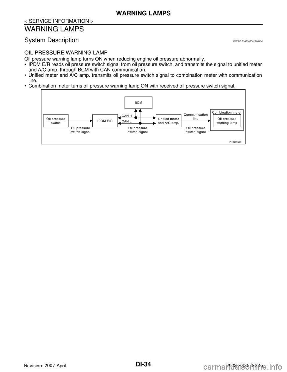
OIL PRESSURE WARNING LAMP
Oil pressure warning lamp turns ON when reducing engine oil pressure abnormally.
IPDM E/R reads oil pressure switch signal from oil pressure switch, and transmits the signal to unified meterand A/C amp. through BCM with CAN communication.
Unified meter and A/C amp. transmits oil pressure s witch signal to combination meter with communication
line.
Combination meter turns oil pressure warning lamp ON with received oil pressure switch signal.
PKIB7655E
3AA93ABC3ACD3AC03ACA3AC03AC63AC53A913A773A893A873A873A8E3A773A983AC73AC93AC03AC3
3A893A873A873A8F3A773A9D3AAF3A8A3A8C3A863A9D3AAF3A8B3A8C
Page 1170 of 3924
DI-44
< SERVICE INFORMATION >
WARNING LAMPS
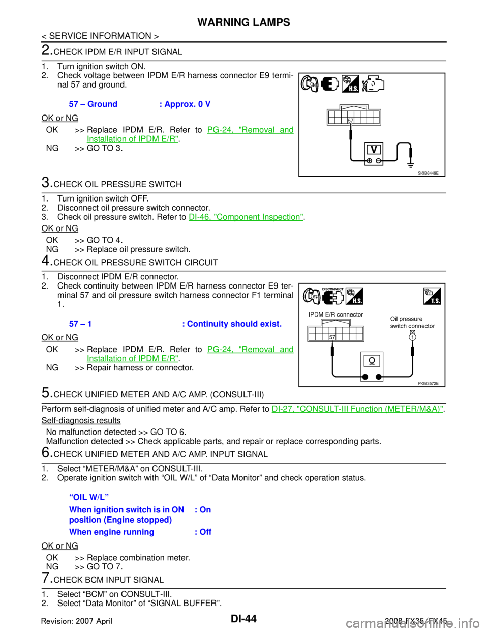
2.CHECK IPDM E/R INPUT SIGNAL
1. Turn ignition switch ON.
2. Check voltage between IPDM E/R harness connector E9 termi- nal 57 and ground.
OK or NG
OK >> Replace IPDM E/R. Refer to PG-24, "Removal and
Installation of IPDM E/R".
NG >> GO TO 3.
3.CHECK OIL PRESSURE SWITCH
1. Turn ignition switch OFF.
2. Disconnect oil pressure switch connector.
3. Check oil pressure switch. Refer to DI-46, "
Component Inspection".
OK or NG
OK >> GO TO 4.
NG >> Replace oil pressure switch.
4.CHECK OIL PRESSURE SWITCH CIRCUIT
1. Disconnect IPDM E/R connector.
2. Check continuity between IPDM E/R harness connector E9 ter- minal 57 and oil pressure switch harness connector F1 terminal
1.
OK or NG
OK >> Replace IPDM E/R. Refer to PG-24, "Removal and
Installation of IPDM E/R".
NG >> Repair harness or connector.
5.CHECK UNIFIED METER AND A/C AMP. (CONSULT-III)
Perform self-diagnosis of unified meter and A/C amp. Refer to DI-27, "
CONSULT-III Function (METER/M&A)".
Self-diagnosis results
No malfunction detected >> GO TO 6.
Malfunction detected >> Check applicable parts, and repair or replace corresponding parts.
6.CHECK UNIFIED METER AND A/C AMP. INPUT SIGNAL
1. Select “METER/M&A” on CONSULT-III.
2. Operate ignition switch with “OIL W/L” of “Data Monitor” and check operation status.
OK or NG
OK >> Replace combination meter.
NG >> GO TO 7.
7.CHECK BCM INPUT SIGNAL
1. Select “BCM” on CONSULT-III.
2. Select “Data Monitor” of “SIGNAL BUFFER”. 57 – Ground : Approx. 0 V
SKIB6449E
57 – 1 : Continuity should exist.
PKIB3572E
“OIL W/L”
When ignition switch is in ON
position (Engine stopped)
: On
When engine running : Off
3AA93ABC3ACD3AC03ACA3AC03AC63AC53A913A773A893A873A873A8E3A773A983AC73AC93AC03AC3
3A893A873A873A8F3A773A9D3AAF3A8A3A8C3A863A9D3AAF3A8B3A8C
Page 1171 of 3924
WARNING LAMPSDI-45
< SERVICE INFORMATION >
C
DE
F
G H
I
J
L
M A
B
DI
N
O P
3. Operate ignition switch with “OIL PRESS SW ” of “Data Monitor” and check operate status.
OK or NG
OK >> Replace BCM. Refer to BCS-13, "Removal and Installation of BCM".
NG >> Replace IPDM E/R. Refer to PG-24, "
Removal and Installation of IPDM E/R".
Oil Pressure Warning Lamp Does Not Turn Off (Oil Pressure Is Normal)INFOID:0000000001328468
NOTE:
For oil pressure inspection, refer to LU-5, "
Inspection" (VQ35DE) or LU-23, "Inspection" (VK45DE)
1.CHECK OIL PRESSURE WARNING LAMP OPERATION
Activate IPDM E/R auto active test. Refer to PG-20, "
Auto Active Test".
Does oil pressure warning lamp blink?
YES >> GO TO 2.
NO >> GO TO 5.
2.CHECK IPDM E/R OUTPUT SIGNAL
1. Turn ignition switch OFF.
2. Disconnect oil pressure switch connector.
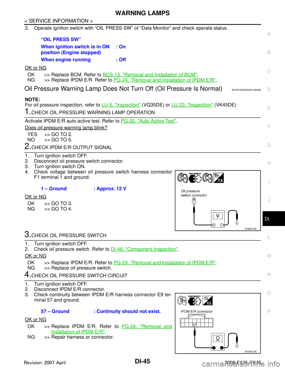
3. Turn ignition switch ON.
4. Check voltage between oil pressure switch harness connector F1 terminal 1 and ground.
OK or NG
OK >> GO TO 3.
NG >> GO TO 4.
3.CHECK OIL PRESSURE SWITCH
1. Turn ignition switch OFF.
2. Check oil pressure switch. Refer to DI-46, "
Component Inspection".
OK or NG
OK >> Replace IPDM E/R. Refer to PG-24, "Removal and Installation of IPDM E/R".
NG >> Replace oil pressure switch.
4.CHECK OIL PRESSURE SWITCH CIRCUIT
1. Turn ignition switch OFF.
2. Disconnect IPDM E/R connector.
3. Check continuity between IPDM E/R harness connector E9 ter- minal 57 and ground.
OK or NG
OK >> Replace IPDM E/R. Refer to PG-24, "Removal and
Installation of IPDM E/R".
NG >> Repair harness or connector. “OIL PRESS SW”
When ignition switch is in ON
position (Engine stopped)
: On
When engine running : Off
1 – Ground : Approx. 12 V
PKIB3573E
57 – Ground : Continuity should not exist.
SKIA5013E
3AA93ABC3ACD3AC03ACA3AC03AC63AC53A913A773A893A873A873A8E3A773A983AC73AC93AC03AC3
3A893A873A873A8F3A773A9D3AAF3A8A3A8C3A863A9D3AAF3A8B3A8C
Page 1172 of 3924
DI-46
< SERVICE INFORMATION >
WARNING LAMPS
5.CHECK IPDM E/R (CONSULT-III)
Perform self-diagnosis of IPDM E/R. Refer to PG-18, "
CONSULT-III Function (IPDM E/R)".
Self-diagnosis results
No malfunction detected >> Replace combination meter.
Malfunction detected >> Check applicable parts, and repair or replace corresponding parts.
Component InspectionINFOID:0000000001328469
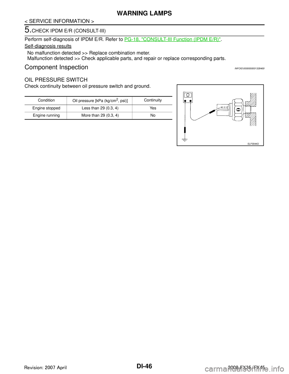
OIL PRESSURE SWITCH
Check continuity between oil pressure switch and ground.
Condition
Oil pressure [kPa (kg/cm2, psi)]Continuity
Engine stopped Less than 29 (0.3, 4) Yes Engine running More than 29 (0.3, 4) No
ELF0044D
3AA93ABC3ACD3AC03ACA3AC03AC63AC53A913A773A893A873A873A8E3A773A983AC73AC93AC03AC3
3A893A873A873A8F3A773A9D3AAF3A8A3A8C3A863A9D3AAF3A8B3A8C
Page 1197 of 3924
LANE DEPARTURE WARNING SYSTEMDI-71
< SERVICE INFORMATION >
C
DE
F
G H
I
J
L
M A
B
DI
N
O P
NOTE:
*: This indicates in a few seconds for the system check during ignition switch ON.
POWER SUPPLY AND GROUND CIRCUIT
With the ignition switch in the ON or START position, power is supplied
through 10A fuse [No. 12, located in the fuse block (J/B)]
to LDW camera unit terminal 1.
Ground is supplied
to LDW camera unit terminals 6 and 12
through grounds M45, M85 and M35.
Action TestINFOID:0000000001328494
LDW SYSTEM RUNNING TEST
WARNING:
Be careful when performing road test.
Understand “Precautions” and “System Description” well before the road test. Refer to DI-69, "
Pre-
caution for Lane Departure Warning (LDW) system" and DI-69, "System Description".
Function Check
Check the LDW system operation according to the c ondition that the warning function works. Refer to DI-69,
"System Description".
Camera Aiming AdjustmentINFOID:0000000001328495
OUTLINE
Adjust the camera aiming every time the LDW camera unit is removed or installed.
CAUTION:
Place the vehicle on the level ground when the camera aiming adjustment is operated.
Follow the CONSULT-III when ad justing the camera aiming. (Camera aiming adjustment cannot be
operated without CONSULT-III.)
PREPARATION
Keep all tires inflated to correct pressures. Adjust the tire pressure to the specified pressure value.
There is no-load in vehicle. Check if coolant, engine oil are filled up to correct level and fuel tank is full.
Shift the gear into “P” position and release the parking brake.
Clean the windshield.
NOTE:
Do not place anything reflective on t he upper surface of instrument panel.
TARGET SETTING
Preparation Aiming Adjustment Jig
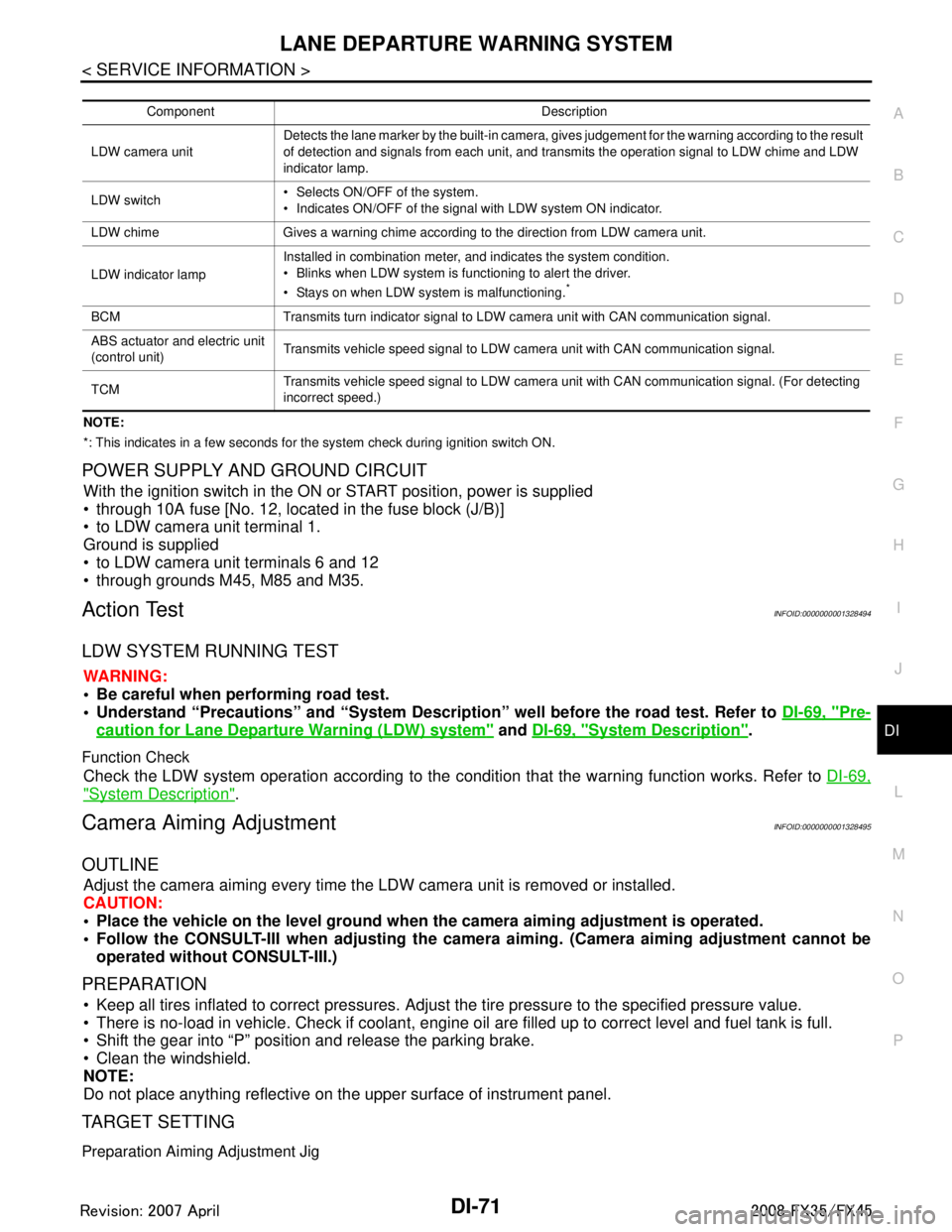
Component Description
LDW camera unit Detects the lane marker by the built-in camera, gives judgement for the warning according to the result
of detection and signals from each unit, and transmits the operation signal to LDW chime and LDW
indicator lamp.
LDW switch Selects ON/OFF of the system.
Indicates ON/OFF of the signal with LDW system ON indicator.
LDW chime Gives a warning chime according to the direction from LDW camera unit.
LDW indicator lamp Installed in combination meter, and indicates the system condition.
Blinks when LDW system is functioning to alert the driver.
Stays on when LDW system is malfunctioning.
*
BCM Transmits turn indicator signal to LDW camera unit with CAN communication signal.
ABS actuator and electric unit
(control unit)
Transmits vehicle speed signal to LDW camera unit with CAN communication signal.
TCM Transmits vehicle speed signal to LDW camera unit with CAN communication signal. (For detecting
incorrect speed.)
3AA93ABC3ACD3AC03ACA3AC03AC63AC53A913A773A893A873A873A8E3A773A983AC73AC93AC03AC3
3A893A873A873A8F3A773A9D3AAF3A8A3A8C3A863A9D3AAF3A8B3A8C
Page 1266 of 3924
![INFINITI FX35 2008 Service Manual
EC-26
< SERVICE INFORMATION >[VQ35DE]
PRECAUTIONS
Precaution
INFOID:0000000001325892
Always use a 12 volt battery as power source.
Do not attempt to disconnect battery cables while engine is
run INFINITI FX35 2008 Service Manual
EC-26
< SERVICE INFORMATION >[VQ35DE]
PRECAUTIONS
Precaution
INFOID:0000000001325892
Always use a 12 volt battery as power source.
Do not attempt to disconnect battery cables while engine is
run](/manual-img/42/57017/w960_57017-1265.png)
EC-26
< SERVICE INFORMATION >[VQ35DE]
PRECAUTIONS
Precaution
INFOID:0000000001325892
Always use a 12 volt battery as power source.
Do not attempt to disconnect battery cables while engine is
running.
Before connecting or disconnecting the ECM harness con-
nector, turn ignition switch OFF and disconnect negative bat-
tery cable. Failure to do so may damage the ECM because
battery voltage is applied to ECM even if ignition switch is
turned OFF.
Before removing parts, turn ig nition switch OFF and then dis-
connect negative battery cable.
Do not disassemble ECM.
If a battery cable is disconnected, the memory will return to
the ECM value.
The ECM will now start to self-c ontrol at its initial value.
Engine operation can vary slight ly when the terminal is dis-
connected. However, this is no t an indication of a malfunc-
tion. Do not replace parts b ecause of a slight variation.
If the battery is disconnected, the following emission-related
diagnostic information will be lost within 24 hours.
- Diagnostic trouble codes
- 1st trip diagnostic trouble codes
- Freeze frame data
- 1st trip freeze frame data
- System readiness test (SRT) codes
- Test values
When connecting ECM harness co nnector, fasten it securely
with a lever as far as it will go as shown in the figure.
When connecting or disconnect ing pin connectors into or
from ECM, take care not to damage pin terminals (bend or
break).
Make sure that there are not any bends or breaks on ECM pin
terminal, when connecting pin connectors.
Securely connect ECM harness connectors.
A poor connection can cause an extremely high (surge) volt-
age to develop in coil and co ndenser, thus resulting in dam-
age to ICs.
Keep engine control system harn ess at least 10 cm (4 in) away
from adjacent harness, to preven t engine control system mal-
functions due to receiving exter nal noise, degraded operation
of ICs, etc.
Keep engine control system parts and harness dry.
SEF289H
PBIB1164E
PBIB1512E
PBIB0090E
3AA93ABC3ACD3AC03ACA3AC03AC63AC53A913A773A893A873A873A8E3A773A983AC73AC93AC03AC3
3A893A873A873A8F3A773A9D3AAF3A8A3A8C3A863A9D3AAF3A8B3A8C
Page 1336 of 3924
![INFINITI FX35 2008 Service Manual
EC-96
< SERVICE INFORMATION >[VQ35DE]
TROUBLE DIAGNOSIS
Symptom Matrix Chart
INFOID:0000000001325930
SYSTEM — BASIC ENGINE CONTROL SYSTEM
Engine operating condition in fail-safe mode Engine speed w INFINITI FX35 2008 Service Manual
EC-96
< SERVICE INFORMATION >[VQ35DE]
TROUBLE DIAGNOSIS
Symptom Matrix Chart
INFOID:0000000001325930
SYSTEM — BASIC ENGINE CONTROL SYSTEM
Engine operating condition in fail-safe mode Engine speed w](/manual-img/42/57017/w960_57017-1335.png)
EC-96
< SERVICE INFORMATION >[VQ35DE]
TROUBLE DIAGNOSIS
Symptom Matrix Chart
INFOID:0000000001325930
SYSTEM — BASIC ENGINE CONTROL SYSTEM
Engine operating condition in fail-safe mode Engine speed will not rise more than 2,500 rpm due to the fuel cut
SYMPTOM
Reference
page
HARD/NO START/RESTART (EXCP. HA)
ENGINE STALL
HESITATION/SURGING/FLAT SPOT
SPARK KNOCK/DETONATION
LACK OF POWER/POOR ACCELERATION
HIGH IDLE/LOW IDLE
ROUGH IDLE/HUNTING
IDLING VIBRATION
SLOW/NO RETURN TO IDLE
OVERHEATS/WATER TEMPERATURE HIGH
EXCESSIVE FUEL CONSUMPTION
EXCESSIVE OIL CONSUMPTION
BATTERY DEAD (UNDER CHARGE)
Warranty symptom code AA AB AC AD AE AF AG AH AJ AK AL AM HA
Fuel Fuel pump circuit 11232 22 3 2 EC-558
Fuel pressure regulator system 334444444 4EC-87
Fuel injector circuit 11232 22 2EC-552
Evaporative emission system 334444444 4EC-40
Air Positive crankcase ventilation sys-
tem 334444444 41
EC-51
Incorrect idle speed adjustment 1 1 1 1 1 EC-80
Electric throttle control actuator 112332222 2 2EC-494,
EC-504
IgnitionIncorrect ignition timing adjustment33111 11 1 EC-80
Ignition circuit 11222 22 2EC-569
Power supply and ground circuit 22333 33 23 EC-140
Mass air flow sensor circuit
1
12 2
222 2 EC-175,
EC-182
Engine coolant temperature sensor circuit
333
EC-193,
EC-204
Air fuel ratio (A/F) sensor EC-220
EC-220
EC-228
EC-236
EC-532
Throttle position sensor circuit
22EC-198
,
EC-302
,
EC-447
,
EC-449
,
EC-518
Accelerator pedal position sensor circuit 3 2 1 EC-424
,
EC-506
,
EC-512
,
EC-524
Knock sensor circuit 2 3 EC-315
3AA93ABC3ACD3AC03ACA3AC03AC63AC53A913A773A893A873A873A8E3A773A983AC73AC93AC03AC3
3A893A873A873A8F3A773A9D3AAF3A8A3A8C3A863A9D3AAF3A8B3A8C