2008 INFINITI FX35 turn signal
[x] Cancel search: turn signalPage 3108 of 3924

LT-6
< SERVICE INFORMATION >
HEADLAMP - XENON TYPE -
to combination meter terminal 7.
With ignition switch in ACC or ON position, power is supplied
through 10A fuse [No. 6, located in fuse block (J/B)]
to BCM terminal 11.
Ground is supplied
to BCM terminals 49 and 52
through grounds M35, M45 and M85,
to IPDM E/R terminals 38 and 60
through grounds E21, E50 and E51,
to combination meter terminals 5, 6 and 15
through grounds M35, M45 and M85.
HEADLAMP OPERATION
Low Beam Operation
With the lighting switch in the 2ND position, the BCM receives input signal requesting the headlamps to illumi-
nate. This input signal is communicated to the IP DM E/R through the CAN communication lines. The CPU
located in the IPDM E/R controls the headlamp lo w relay coil, which when energized, directs power
through 15A fuse (No. 76, located in IPDM E/R)
through IPDM E/R terminal 20
to front combination lamp RH terminal 6,
through 15A fuse (No. 86, located in IPDM E/R)
through IPDM E/R terminal 30
to front combination lamp LH terminal 6.
Ground is supplied
to front combination lamp RH and LH terminals 7
through grounds E21, E50 and E51,
With power and ground supplied, low beam headlamps illuminate.
High Beam Operation/Flash-to-Pass Operation
With the lighting switch in the 2ND position and placed in the HIGH or PASS position, the BCM receives input
signal requesting the headlamp high beams to illuminate. Th is input signal is communicated to the IPDM E/R
through the CAN communication lines. The CPU located in the IPDM E/R controls the headlamp high relay
coil and low relay coil, which when energized, directs power
through 15A fuse (No. 76, located in IPDM E/R)
through IPDM E/R terminal 20
to front combination lamp RH terminal 6,
through 15A fuse (No. 86, located in IPDM E/R)
through IPDM E/R terminal 30
to front combination lamp LH terminal 6,
through 10A fuse (No. 72, located in IPDM E/R)
through IPDM E/R terminal 27
to front combination lamp RH terminal 5,
through 10A fuse (No. 74, located in IPDM E/R)
through IPDM E/R terminal 28
to front combination lamp LH terminal 5.
Ground is supplied
to front combination lamp RH and LH terminals 7
through grounds E21, E50 and E51,
With power and ground supplied, the high beam headlamps illuminate.
If voltage is applied to a high beam solenoid, the bulb shade will move, even a xenon head lamp bulb comes
out, and a high beam and a low beam are changed.
The unified meter and A/C amp. that received the hi gh beam request signal by BCM through the CAN commu-
nication makes a high beam indicator lamp turn on in combination meter.
COMBINATION SWITCH READING FUNCTION
Refer to BCS-4, "System Description".
EXTERIOR LAMP BATTERY SAVER CONTROL
When the combination switch (lighting switch) is in the 2ND position (ON), and the ignition switch is turned
from ON or ACC to OFF, the battery saver control function is activated.
Under this condition, the headlamps remain illumi nated for 5 minutes, then the headlamps are turned OFF.
3AA93ABC3ACD3AC03ACA3AC03AC63AC53A913A773A893A873A873A8E3A773A983AC73AC93AC03AC3
3A893A873A873A8F3A773A9D3AAF3A8A3A8C3A863A9D3AAF3A8B3A8C
Page 3114 of 3924
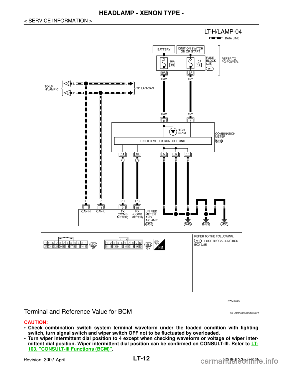
LT-12
< SERVICE INFORMATION >
HEADLAMP - XENON TYPE -
Terminal and Reference Value for BCM
INFOID:0000000001328271
CAUTION:
Check combination switch system terminal waveform under the loaded condition with lighting
switch, turn signal switch and wiper switch OFF not to be fluctuated by overloaded.
Turn wiper intermittent dial posi tion to 4 except when checking wavef orm or voltage of wiper inter-
mittent dial position. Wiper intermittent dial position can be confirmed on CONSULT-III. Refer to LT-
103, "CONSULT-III Functions (BCM)".
TKWM4292E
3AA93ABC3ACD3AC03ACA3AC03AC63AC53A913A773A893A873A873A8E3A773A983AC73AC93AC03AC3
3A893A873A873A8F3A773A9D3AAF3A8A3A8C3A863A9D3AAF3A8B3A8C
Page 3115 of 3924
HEADLAMP - XENON TYPE -LT-13
< SERVICE INFORMATION >
C
DE
F
G H
I
J
L
M A
B
LT
N
O P
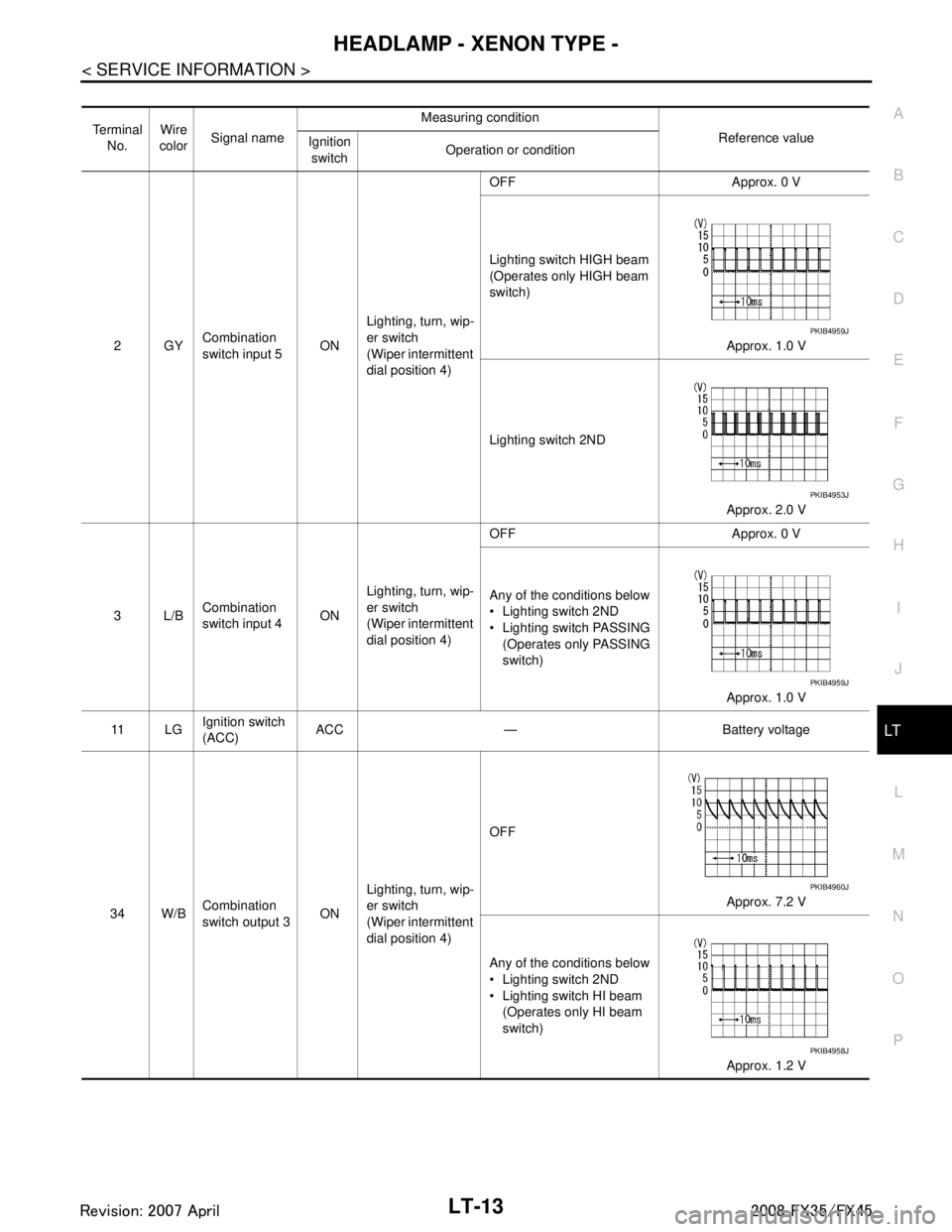
Te r m i n a l No. Wire
color Signal name Measuring condition
Reference value
Ignition
switch Operation or condition
2GY Combination
switch input 5 ONLighting, turn, wip-
er switch
(Wiper intermittent
dial position 4) OFF Approx. 0 V
Lighting switch HIGH beam
(Operates only HIGH beam
switch)
Approx. 1.0 V
Lighting switch 2ND Approx. 2.0 V
3L/B Combination
switch input 4 ONLighting, turn, wip-
er switch
(Wiper intermittent
dial position 4) OFF Approx. 0 V
Any of the conditions below
Lighting switch 2ND
Lighting switch PASSING
(Operates only PASSING
switch)
Approx. 1.0 V
11 L G Ignition switch
(ACC) ACC — Battery voltage
34 W/B Combination
switch output 3 ONLighting, turn, wip-
er switch
(Wiper intermittent
dial position 4) OFF
Approx. 7.2 V
Any of the conditions below
Lighting switch 2ND
Lighting switch HI beam (Operates only HI beam
switch)
Approx. 1.2 V
PKIB4959J
PKIB4953J
PKIB4959J
PKIB4960J
PKIB4958J
3AA93ABC3ACD3AC03ACA3AC03AC63AC53A913A773A893A873A873A8E3A773A983AC73AC93AC03AC3
3A893A873A873A8F3A773A9D3AAF3A8A3A8C3A863A9D3AAF3A8B3A8C
Page 3116 of 3924
LT-14
< SERVICE INFORMATION >
HEADLAMP - XENON TYPE -
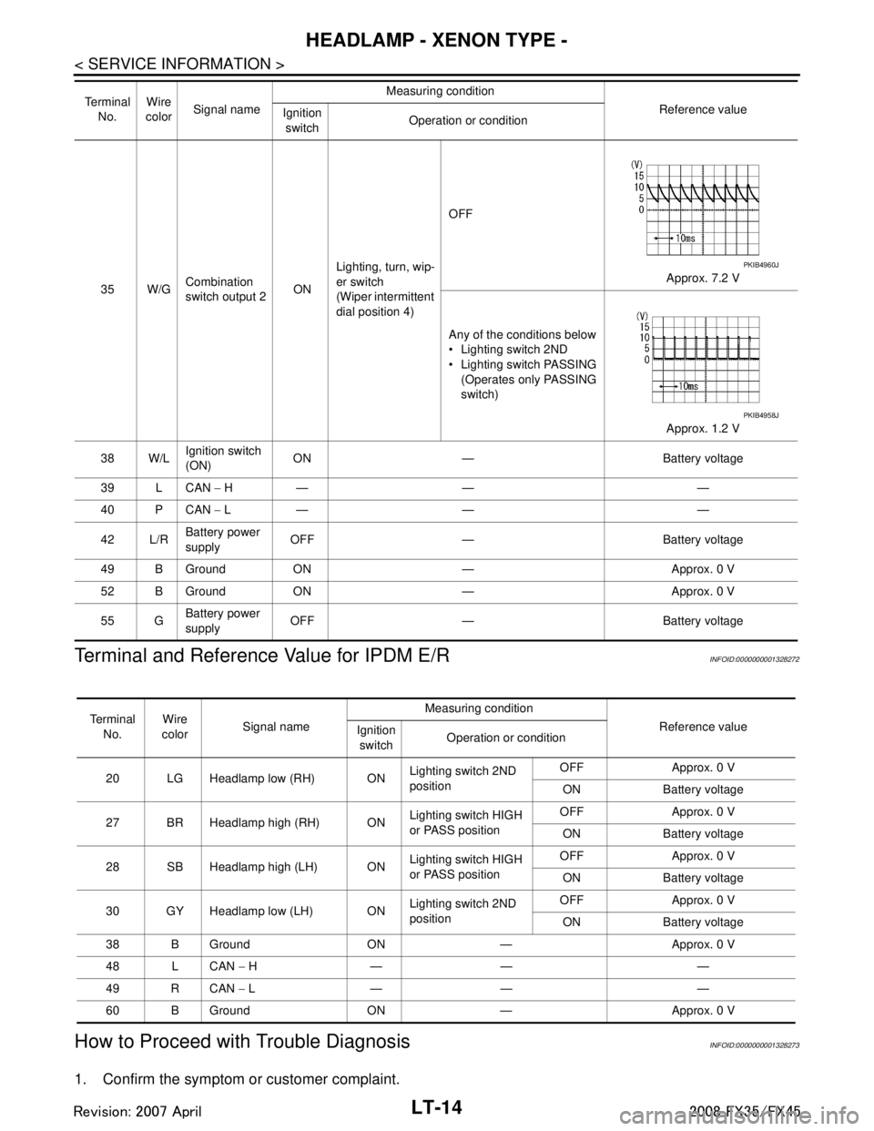
Terminal and Reference Value for IPDM E/R
INFOID:0000000001328272
How to Proceed with Trouble DiagnosisINFOID:0000000001328273
1. Confirm the symptom or customer complaint.
35 W/G Combination
switch output 2 ONLighting, turn, wip-
er switch
(Wiper intermittent
dial position 4) OFF
Approx. 7.2 V
Any of the conditions below
Lighting switch 2ND
Lighting switch PASSING (Operates only PASSING
switch)
Approx. 1.2 V
38 W/L Ignition switch
(ON)
ON — Battery voltage
39 L CAN − H— — —
40 P CAN − L— — —
42 L/R Battery power
supply
OFF — Battery voltage
49 B Ground ON — Approx. 0 V
52 B Ground ON — Approx. 0 V
55 G Battery power
supply OFF — Battery voltage
Te r m i n a l
No. Wire
color Signal name Measuring condition
Reference value
Ignition
switch Operation or condition
PKIB4960J
PKIB4958J
Te r m i n a l
No. Wire
color Signal name Measuring condition
Reference value
Ignition
switch Operation or condition
20 LG Headlamp low (RH) ON Lighting switch 2ND
positionOFF Approx. 0 V
ON Battery voltage
27 BR Headlamp high (RH) ON Lighting switch HIGH
or PASS positionOFF Approx. 0 V
ON Battery voltage
28 SB Headlamp high (LH) ON Lighting switch HIGH
or PASS positionOFF Approx. 0 V
ON Battery voltage
30 GY Headlamp low (LH) ON Lighting switch 2ND
positionOFF Approx. 0 V
ON Battery voltage
38 B Ground ON — Approx. 0 V
48 L CAN − H— — —
49 R CAN − L— — —
60 B Ground ON — Approx. 0 V
3AA93ABC3ACD3AC03ACA3AC03AC63AC53A913A773A893A873A873A8E3A773A983AC73AC93AC03AC3
3A893A873A873A8F3A773A9D3AAF3A8A3A8C3A863A9D3AAF3A8B3A8C
Page 3119 of 3924

HEADLAMP - XENON TYPE -LT-17
< SERVICE INFORMATION >
C
DE
F
G H
I
J
L
M A
B
LT
N
O P
NOTE:
1. Vehicles without auto light system display this item, but cannot be monitored.
2. Vehicles without daytime light system display this item, but cannot be monitored.
3. This item is displayed, but cannot be monitored.
ACTIVE TEST
Display Item List
NOTE:
1. Vehicles without daytime light lamp system display this item, but cannot be tested.
2. This item is displayed, but cannot be tested.
CONSULT-III Functions (IPDM E/R)INFOID:0000000001328276
CONSULT-III can display each diagnostic item us ing the diagnostic test modes shown following.
CONSULT-III BASIC OPERATION
Refer to GI-34, "Description".
DATA MONITOR
All Signals, Main Signals, Selection From Menu
DOOR SW - DR “ON/OFF” Displays status of driver door as judged from driver door switch signal. (Door is open: ON/
Door is closed: OFF)
DOOR SW - AS “ON/OFF” Displays status of passenger door as judged from passenger door switch signal. (Door is
open: ON/Door is closed: OFF)
DOOR SW - RR “ON/OFF” Displays status of rear door as judged from rear door switch (RH) signal. (Door is open: ON/
Door is closed: OFF)
DOOR SW - RL “ON/OFF” Displays status of rear door as judged from rear door switch (LH) signal. (Door is open: ON/
Door is closed: OFF)
BACK DOOR SW “ON/OFF” Displays status of back door as judged from back door switch signal. (Door is open: ON/
Door is closed: OFF)
TURN SIGNAL R “ON/OFF” Display s status (Turn right: ON/Others: OFF) as judged from lighting switch signal.
TURN SIGNAL L “ON/OFF” Display s status (Turn left: ON/Others: OFF) as judged from lighting switch signal.
ENGINE RUN
NOTE 2“ON/OFF” Displays status (Engine running: ON/Others: OFF) as judged from engine status signal.
PKB SW
NOTE 2“ON/OFF” Displays status (Parking brake switch: ON/Others: OFF) as judged from parking brake
switch signal.
CARGO LAMP SW
NOTE 3 “OFF” —
OPTICAL SENSOR
NOTE 1 “0 - 5 V” Displays “outside brightness (close to 5 V when light/close to 0 V when dark)” judged from
optical sensor signal.
Monitor item Contents
Te s t i t e m D e s c r i p t i o n
TAIL LAMP Allows tail lamp relay to operate by switching ON-OFF.
HEAD LAMP Allows headlamp relay to operate by switching ON-OFF.
FR FOG LAMP Allows front fog lamp relay to operate by switching ON-OFF.
DTRL
NOTE 1Allows daytime light lamp operate by switching ON-OFF
CORNERING LAMP
NOTE 2—
Check Item, Diagnosis Mode Description
SELF-DIAGNOSTIC RESULTS Refer to PG-18, "
CONSULT-III Function (IPDM E/R)".
DATA MONITOR The input/output data of IPDM E/R is displayed in real time.
CAN DIAG SUPPORT MNTR The result of transmit/receive diagnosis of CAN communication can be read.
ACTIVE TEST IPDM E/R sends a drive signal to electronic components to check their operation.
3AA93ABC3ACD3AC03ACA3AC03AC63AC53A913A773A893A873A873A8E3A773A983AC73AC93AC03AC3
3A893A873A873A8F3A773A9D3AAF3A8A3A8C3A863A9D3AAF3A8B3A8C
Page 3121 of 3924
HEADLAMP - XENON TYPE -LT-19
< SERVICE INFORMATION >
C
DE
F
G H
I
J
L
M A
B
LT
N
O P
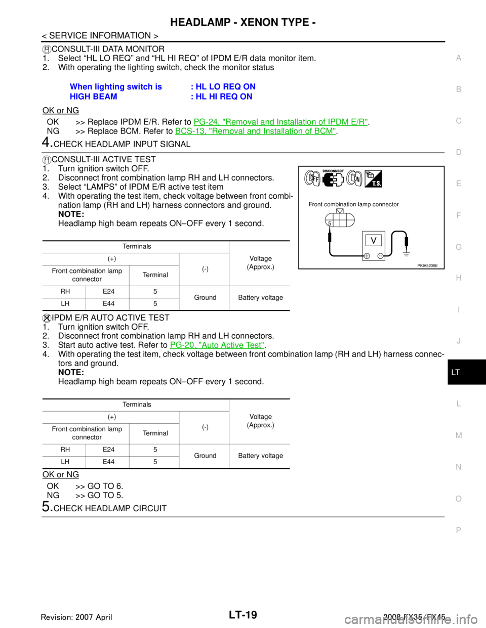
CONSULT-III DATA MONITOR
1. Select “HL LO REQ” and “HL HI RE Q” of IPDM E/R data monitor item.
2. With operating the lighting switch, check the monitor status
OK or NG
OK >> Replace IPDM E/R. Refer to PG-24, "Removal and Installation of IPDM E/R".
NG >> Replace BCM. Refer to BCS-13, "
Removal and Installation of BCM".
4.CHECK HEADLAMP INPUT SIGNAL
CONSULT-III ACTIVE TEST
1. Turn ignition switch OFF.
2. Disconnect front combination lamp RH and LH connectors.
3. Select “LAMPS” of IPDM E/R active test item
4. With operating the test item, check voltage between front combi- nation lamp (RH and LH) harness connectors and ground.
NOTE:
Headlamp high beam repeats ON–OFF every 1 second.
IPDM E/R AUTO ACTIVE TEST
1. Turn ignition switch OFF.
2. Disconnect front combination lamp RH and LH connectors.
3. Start auto active test. Refer to PG-20, "
Auto Active Test".
4. With operating the test item, check voltage betw een front combination lamp (RH and LH) harness connec-
tors and ground.
NOTE:
Headlamp high beam repeats ON–OFF every 1 second.
OK or NG
OK >> GO TO 6.
NG >> GO TO 5.
5.CHECK HEADLAMP CIRCUIT When lighting switch is
HIGH BEAM
: HL LO REQ ON
: HL HI REQ ON
Te r m i n a l s
Voltag e
(Approx.)
(+)
(-)
Front combination lamp
connector Te r m i n a l
RH E24 5 Ground Battery voltage
LH E44 5
Te r m i n a l s Voltag e
(Approx.)
(+)
(-)
Front combination lamp
connector Te r m i n a l
RH E24 5 Ground Battery voltage
LH E44 5
PKIA5205E
3AA93ABC3ACD3AC03ACA3AC03AC63AC53A913A773A893A873A873A8E3A773A983AC73AC93AC03AC3
3A893A873A873A8F3A773A9D3AAF3A8A3A8C3A863A9D3AAF3A8B3A8C
Page 3122 of 3924
LT-20
< SERVICE INFORMATION >
HEADLAMP - XENON TYPE -
1. Turn ignition switch OFF.
2. Disconnect IPDM E/R connector.
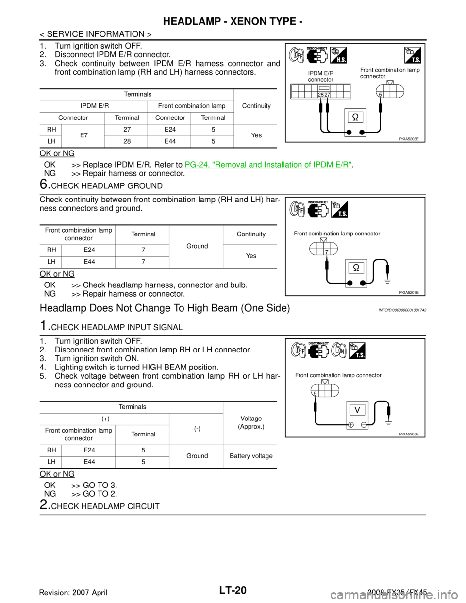
3. Check continuity between IPDM E/R harness connector andfront combination lamp (RH and LH) harness connectors.
OK or NG
OK >> Replace IPDM E/R. Refer to PG-24, "Removal and Installation of IPDM E/R".
NG >> Repair harness or connector.
6.CHECK HEADLAMP GROUND
Check continuity between front combination lamp (RH and LH) har-
ness connectors and ground.
OK or NG
OK >> Check headlamp harness, connector and bulb.
NG >> Repair harness or connector.
Headlamp Does Not Change To High Beam (One Side)INFOID:0000000001381743
1.CHECK HEADLAMP INPUT SIGNAL
1. Turn ignition switch OFF.
2. Disconnect front combination lamp RH or LH connector.
3. Turn ignition switch ON.
4. Lighting switch is turned HIGH BEAM position.
5. Check voltage between front combination lamp RH or LH har- ness connector and ground.
OK or NG
OK >> GO TO 3.
NG >> GO TO 2.
2.CHECK HEADLAMP CIRCUIT
Te r m i n a l s Continuity
IPDM E/R Front combination lamp
Connector Terminal Connector Terminal
RH E7 27 E24 5
Ye s
LH 28 E44 5
PKIA5206E
Front combination lamp
connector Te r m i n a l
Ground Continuity
RH E24 7 Ye s
LH E44 7
PKIA5207E
Te r m i n a l s
Vo l ta g e
(Approx.)
(+)
(-)
Front combination lamp
connector Te r m i n a l
RH E24 5 Ground Battery voltage
LH E44 5
PKIA5205E
3AA93ABC3ACD3AC03ACA3AC03AC63AC53A913A773A893A873A873A8E3A773A983AC73AC93AC03AC3
3A893A873A873A8F3A773A9D3AAF3A8A3A8C3A863A9D3AAF3A8B3A8C
Page 3123 of 3924
HEADLAMP - XENON TYPE -LT-21
< SERVICE INFORMATION >
C
DE
F
G H
I
J
L
M A
B
LT
N
O P
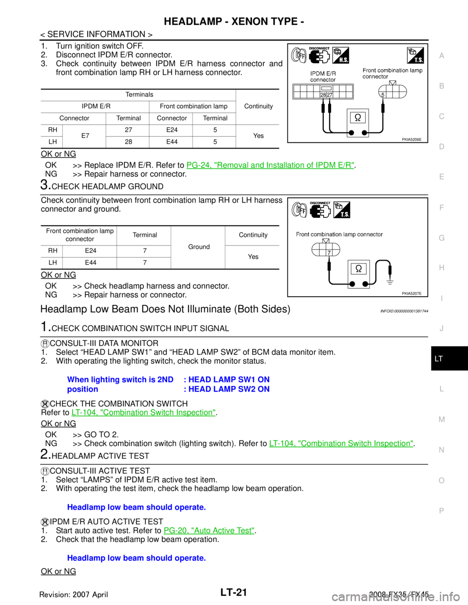
1. Turn ignition switch OFF.
2. Disconnect IPDM E/R connector.
3. Check continuity between IPDM E/R harness connector and front combination lamp RH or LH harness connector.
OK or NG
OK >> Replace IPDM E/R. Refer to PG-24, "Removal and Installation of IPDM E/R".
NG >> Repair harness or connector.
3.CHECK HEADLAMP GROUND
Check continuity between front combination lamp RH or LH harness
connector and ground.
OK or NG
OK >> Check headlamp harness and connector.
NG >> Repair harness or connector.
Headlamp Low Beam Does No t Illuminate (Both Sides)INFOID:0000000001381744
1.CHECK COMBINATION SWITCH INPUT SIGNAL
CONSULT-III DATA MONITOR
1. Select “HEAD LAMP SW1” and “HEAD LA MP SW2” of BCM data monitor item.
2. With operating the lighting switch, check the monitor status.
CHECK THE COMBINATION SWITCH
Refer to LT-104, "
Combination Switch Inspection".
OK or NG
OK >> GO TO 2.
NG >> Check combination switch (lighting switch). Refer to LT-104, "
Combination Switch Inspection".
2.HEADLAMP ACTIVE TEST
CONSULT-III ACTIVE TEST
1. Select “LAMPS” of IPDM E/R active test item.
2. With operating the test item, check the headlamp low beam operation.
IPDM E/R AUTO ACTIVE TEST
1. Start auto active test. Refer to PG-20, "
Auto Active Test".
2. Check that the headlamp low beam operation.
OK or NG
Te r m i n a l s
Continuity
IPDM E/R Front combination lamp
Connector Terminal Connector Terminal
RH E7 27 E24 5
Ye s
LH 28 E44 5
PKIA5206E
Front combination lamp
connector Terminal
Ground Continuity
RH E24 7 Ye s
LH E44 7
PKIA5207E
When lighting switch is 2ND
position : HEAD LAMP SW1 ON
: HEAD LAMP SW2 ON
Headlamp low beam should operate.
Headlamp low beam should operate.
3AA93ABC3ACD3AC03ACA3AC03AC63AC53A913A773A893A873A873A8E3A773A983AC73AC93AC03AC3
3A893A873A873A8F3A773A9D3AAF3A8A3A8C3A863A9D3AAF3A8B3A8C