2008 INFINITI FX35 turn signal
[x] Cancel search: turn signalPage 2958 of 3924
POWER WINDOW SYSTEMGW-45
< SERVICE INFORMATION >
C
DE
F
G H
J
K L
M A
B
GW
N
O P
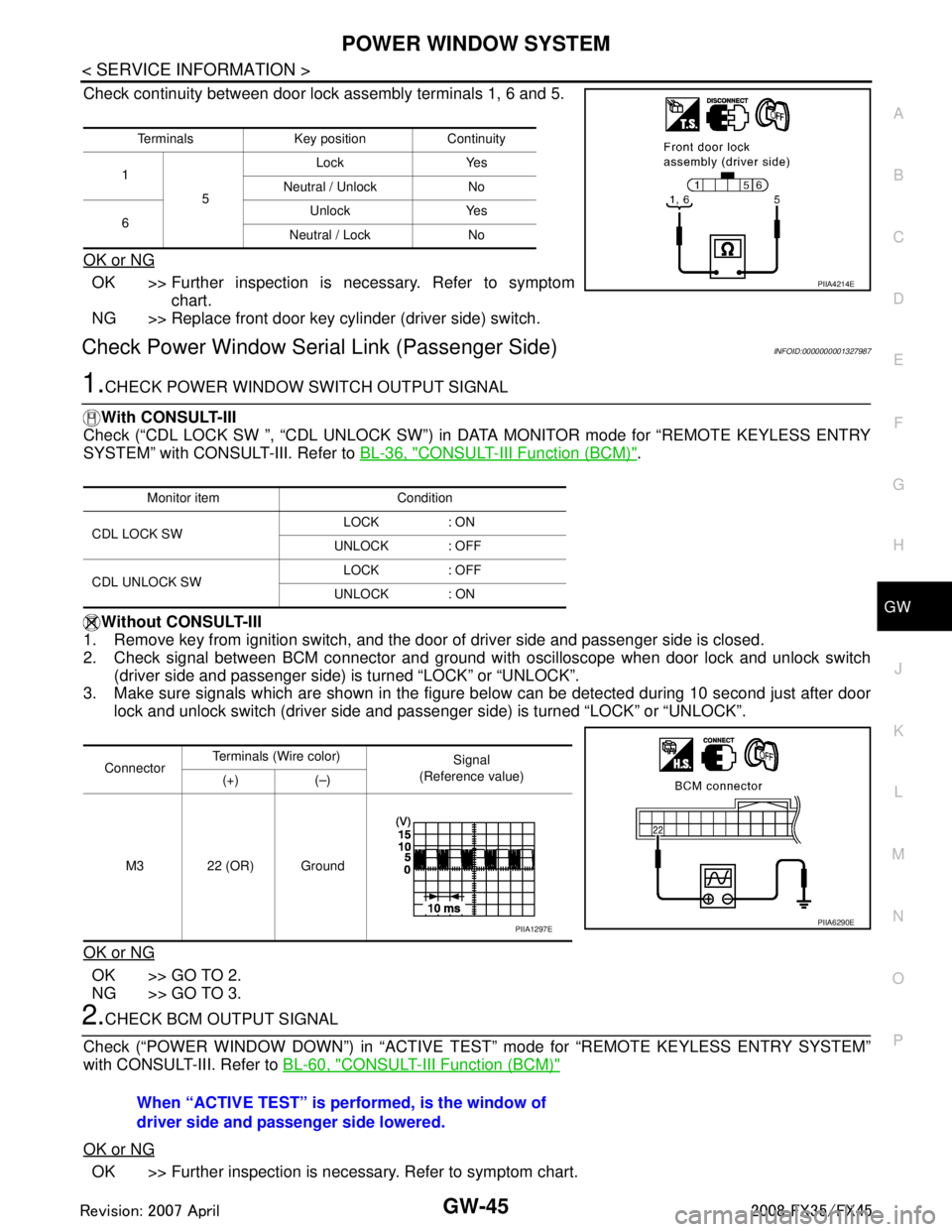
Check continuity between door lock assembly terminals 1, 6 and 5.
OK or NG
OK >> Further inspection is necessary. Refer to symptom chart.
NG >> Replace front door key cylinder (driver side) switch.
Check Power Window Serial Link (Passenger Side)INFOID:0000000001327987
1.CHECK POWER WINDOW SWITCH OUTPUT SIGNAL
With CONSULT-III
Check (“CDL LOCK SW ”, “CDL UNLOCK SW”) in DATA MONITOR mode for “REMOTE KEYLESS ENTRY
SYSTEM” with CONSULT-III. Refer to BL-36, "
CONSULT-III Function (BCM)".
Without CONSULT-III
1. Remove key from ignition switch, and the door of driver side and passenger side is closed.
2. Check signal between BCM connector and ground wit h oscilloscope when door lock and unlock switch
(driver side and passenger side) is turned “LOCK” or “UNLOCK”.
3. Make sure signals which are shown in the figure below can be detected during 10 second just after door
lock and unlock switch (driver side and passenger side) is turned “LOCK” or “UNLOCK”.
OK or NG
OK >> GO TO 2.
NG >> GO TO 3.
2.CHECK BCM OUTPUT SIGNAL
Check (“POWER WINDOW DOWN”) in “ACTIVE T EST” mode for “REMOTE KEYLESS ENTRY SYSTEM”
with CONSULT-III. Refer to BL-60, "
CONSULT-III Function (BCM)"
OK or NG
OK >> Further inspection is necessary. Refer to symptom chart.
Terminals Key position Continuity
1 5 Lock Yes
Neutral / Unlock No
6 Unlock Yes
Neutral / Lock No
PIIA4214E
Monitor item Condition
CDL LOCK SW LOCK : ON
UNLOCK : OFF
CDL UNLOCK SW LOCK : OFF
UNLOCK : ON
Connector Terminals (W
ire color)
Signal
(Reference value)
(+) (–)
M3 22 (OR) Ground
PIIA6290EPIIA1297E
When “ACTIVE TEST” is performed, is the window of
driver side and passenger side lowered.
3AA93ABC3ACD3AC03ACA3AC03AC63AC53A913A773A893A873A873A8E3A773A983AC73AC93AC03AC3
3A893A873A873A8F3A773A9D3AAF3A8A3A8C3A863A9D3AAF3A8B3A8C
Page 2959 of 3924
GW-46
< SERVICE INFORMATION >
POWER WINDOW SYSTEM
NG >> Replace BCM.
3.CHECK POWER WINDOW SWITCH GROUND
1. Turn ignition switch OFF.
2. Disconnect power window main switch and front power window switch (passenger side) connector.
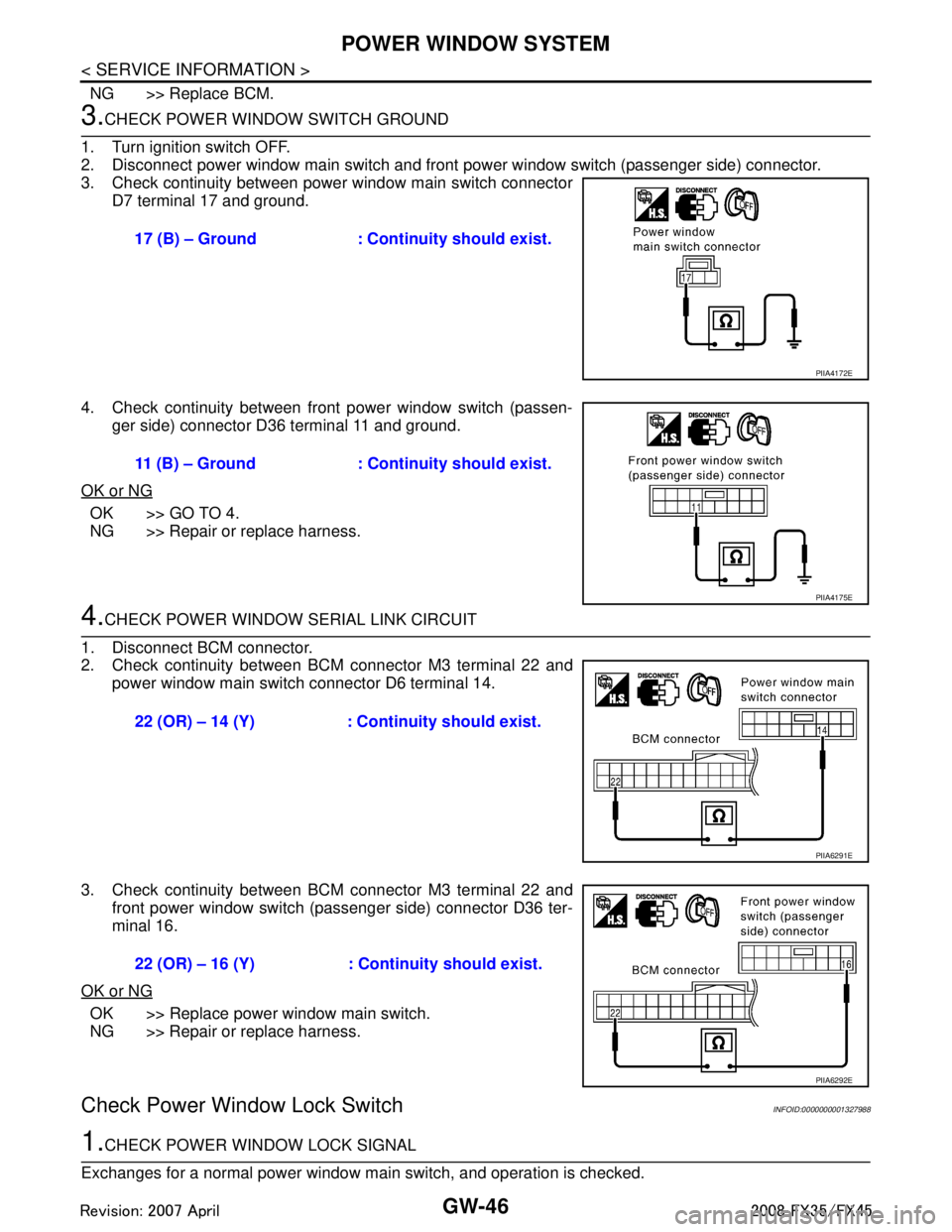
3. Check continuity between power window main switch connector D7 terminal 17 and ground.
4. Check continuity between front power window switch (passen- ger side) connector D36 terminal 11 and ground.
OK or NG
OK >> GO TO 4.
NG >> Repair or replace harness.
4.CHECK POWER WINDOW SERIAL LINK CIRCUIT
1. Disconnect BCM connector.
2. Check continuity between BCM connector M3 terminal 22 and power window main switch connector D6 terminal 14.
3. Check continuity between BCM connector M3 terminal 22 and front power window switch (passenger side) connector D36 ter-
minal 16.
OK or NG
OK >> Replace power window main switch.
NG >> Repair or replace harness.
Check Power Window Lock SwitchINFOID:0000000001327988
1.CHECK POWER WINDOW LOCK SIGNAL
Exchanges for a normal power window main switch, and operation is checked. 17 (B) – Ground : Continuity should exist.
PIIA4172E
11 (B) – Ground : Continuity should exist.
PIIA4175E
22 (OR) – 14 (Y) : Cont
inuity should exist.
PIIA6291E
22 (OR) – 16 (Y) : Cont inuity should exist.
PIIA6292E
3AA93ABC3ACD3AC03ACA3AC03AC63AC53A913A773A893A873A873A8E3A773A983AC73AC93AC03AC3
3A893A873A873A8F3A773A9D3AAF3A8A3A8C3A863A9D3AAF3A8B3A8C
Page 2974 of 3924
REAR WINDOW DEFOGGERGW-61
< SERVICE INFORMATION >
C
DE
F
G H
J
K L
M A
B
GW
N
O P
through body grounds M35, M45 and M85,
to A/C and AV switch terminal 5
through body grounds M35, M45 and M85,
to IPDM E/R terminals 38 and 60
through body grounds E21, E50 and E51.
When rear window defogger switch in A/C and AV switch is turned to ON,
Ground is supplied
to BCM terminal 9
through A/C and AV switch terminal 16
through A/C and AV switch terminal 5 and
through body grounds M35, M45 and M85.
Then rear window defogger switch is illuminated.
Then BCM recognizes that rear window defogger switch is turned to ON.
Then it sends rear window defogger switch signals to IPDM E/R, display control unit via DATA LINE (CAN H,
CAN L).
When display control unit receives rear window defogger switch signals, and display on the screen.
When IPDM E/R receives rear window defogger switch signals,
Ground is supplied
to rear window defogger relay terminal 2
through IPDM E/R terminal 52
through IPDM E/R terminals 38 and 60 and
through body grounds E21, E50 and E51.
And then rear window defogger relay is energized.
When rear window defogger relay is turned ON, signals are transmitted.
through rear window defogger relay terminals 5 and 7
to rear window defogger terminal 1
Rear window defogger terminal 2 is grounded through grounds B15 and B45.
With power and ground supplied, rear window def ogger filaments heat and defog the rear window.
When rear window defogger relay is turned to ON,
Power is supplied
through rear window defogger relay terminal 7
through fuse block (J/B) terminal 2C
through 15A fuse [No. 8, located in the fuse block (J/B)] and
through fuse block (J/B) terminal 5B
to door mirror defogger (driver side and passenger side) terminal 4.
Door mirror defogger (driver side and passenger side) terminal 3 is grounded through body grounds M35, M45
and M85.
With power and ground supplied, rear window defogger filaments heat and defog the rear window and door
mirror defogger filaments heat and defog the mirror.
CAN Communication System DescriptionINFOID:0000000001328000
CAN (Controller Area Network) is a serial communication li ne for real time application. It is an on-vehicle mul-
tiplex communication line with high data communication speed and excellent error detection ability. Many elec-
tronic control units are equipped onto a vehicle, and each control unit shares information and links with other
control units during operation (not independent). In CAN communication, control units are connected with 2
communication lines (CAN H line, CAN L line) allowing a high rate of information transmission with less wiring.
Each control unit transmits/receives data but selectively reads required data only.
CAN Communication UnitINFOID:0000000001328001
Refer to LAN-43, "CAN System Specification Chart".
3AA93ABC3ACD3AC03ACA3AC03AC63AC53A913A773A893A873A873A8E3A773A983AC73AC93AC03AC3
3A893A873A873A8F3A773A9D3AAF3A8A3A8C3A863A9D3AAF3A8B3A8C
Page 2983 of 3924
GW-70
< SERVICE INFORMATION >
REAR WINDOW DEFOGGER
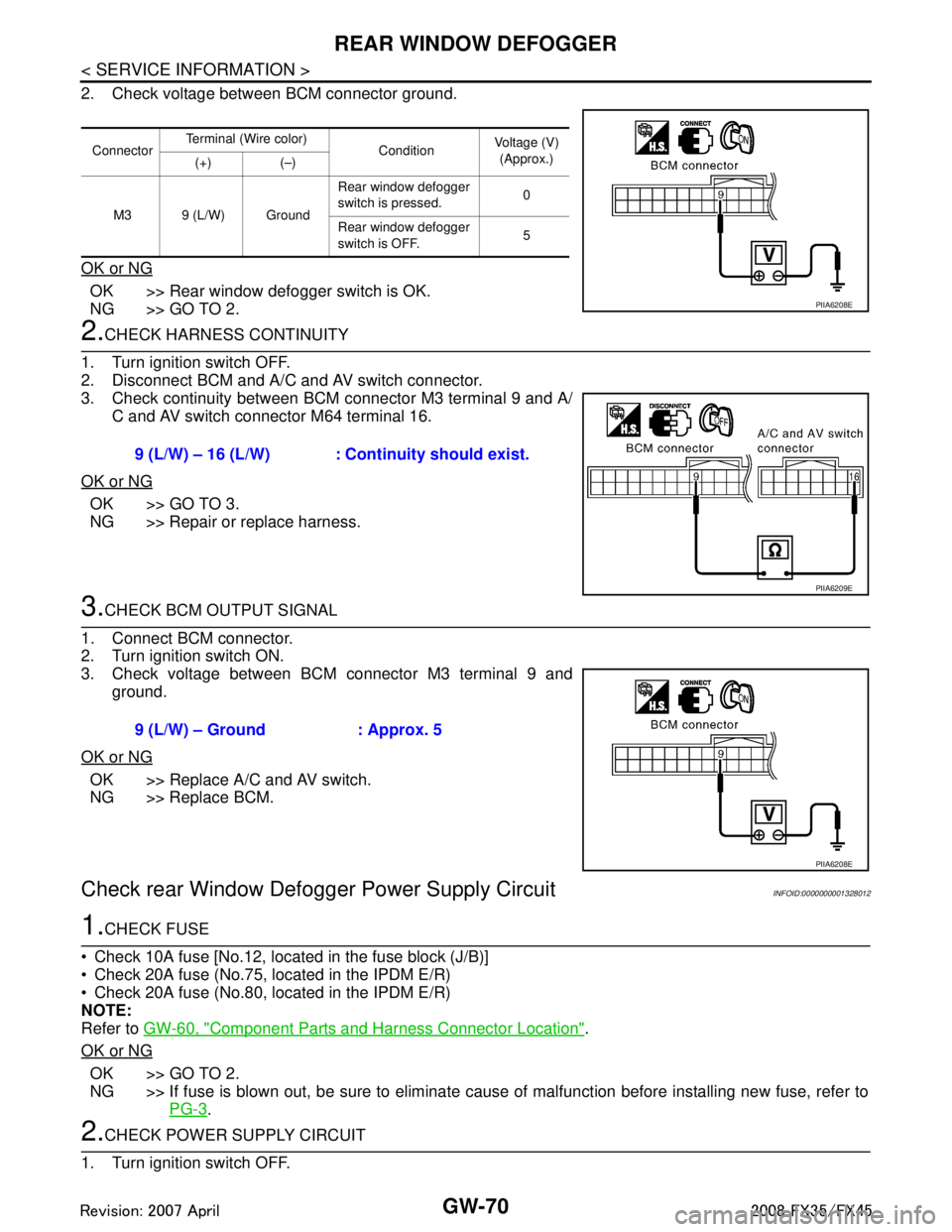
2. Check voltage between BCM connector ground.
OK or NG
OK >> Rear window defogger switch is OK.
NG >> GO TO 2.
2.CHECK HARNESS CONTINUITY
1. Turn ignition switch OFF.
2. Disconnect BCM and A/C and AV switch connector.
3. Check continuity between BCM connector M3 terminal 9 and A/ C and AV switch connector M64 terminal 16.
OK or NG
OK >> GO TO 3.
NG >> Repair or replace harness.
3.CHECK BCM OUTPUT SIGNAL
1. Connect BCM connector.
2. Turn ignition switch ON.
3. Check voltage between BCM connector M3 terminal 9 and ground.
OK or NG
OK >> Replace A/C and AV switch.
NG >> Replace BCM.
Check rear Window Defogger Power Supply CircuitINFOID:0000000001328012
1.CHECK FUSE
Check 10A fuse [No.12, located in the fuse block (J/B)]
Check 20A fuse (No.75, located in the IPDM E/R)
Check 20A fuse (No.80, located in the IPDM E/R)
NOTE:
Refer to GW-60, "
Component Parts and Harness Connector Location".
OK or NG
OK >> GO TO 2.
NG >> If fuse is blown out, be sure to eliminate cause of malfunction before installing new fuse, refer to PG-3
.
2.CHECK POWER SUPPLY CIRCUIT
1. Turn ignition switch OFF.
Connector Terminal (Wire color)
ConditionVoltage (V)
(Approx.)
(+) (–)
M3 9 (L/W) Ground Rear window defogger
switch is pressed.
0
Rear window defogger
switch is OFF. 5
PIIA6208E
9 (L/W) – 16 (L/W) : Cont
inuity should exist.
PIIA6209E
9 (L/W) – Ground : Approx. 5
PIIA6208E
3AA93ABC3ACD3AC03ACA3AC03AC63AC53A913A773A893A873A873A8E3A773A983AC73AC93AC03AC3
3A893A873A873A8F3A773A9D3AAF3A8A3A8C3A863A9D3AAF3A8B3A8C
Page 2985 of 3924

GW-72
< SERVICE INFORMATION >
REAR WINDOW DEFOGGER
3. Check continuity between IPDM E/R connector E9 terminal 52and rear window defogger relay connector E13 terminal 2.
OK or NG
OK >> GO TO 6.
NG >> Repair or replace harness.
6.CHECK REAR WINDOW DEFOGGER RELAY OUTPUT SIGNAL
1. Connect IPDM E/R connector and rear window defogger relay.
2. Turn ignition switch ON.
3. Check voltage between IPDM E/R connector E9 terminal 52 and ground.
OK or NG
OK >> Check condition of harness and connector.
NG >> Replace IPDM E/R.
Check Rear Window Defogger CircuitINFOID:0000000001328013
1.CHECK POWER SUPPLY CIRCUIT 1
1. Turn ignition switch OFF.
2. Disconnect rear window defogger connector.
3. Turn ignition switch ON.
4. Check voltage between rear window defogger connector and ground.
OK or NG
OK >> GO TO 2.
NG >> GO TO 3.
2.CHECK GROUND CIRCUIT
1. Turn ignition switch OFF. 52 (G) – 2 (G) : Continuity should exist.
PIIA6211E
52 (G) – Ground : Battery voltage
PIIA6210E
Connector
Terminal (Wire color)
ConditionVoltage (V)
(Approx.)
(+) (–)
D104 1(W) Ground Rear window defogger
switch ON.
Battery voltage
Rear window defogger
switch OFF. 0
PIIA9347E
3AA93ABC3ACD3AC03ACA3AC03AC63AC53A913A773A893A873A873A8E3A773A983AC73AC93AC03AC3
3A893A873A873A8F3A773A9D3AAF3A8A3A8C3A863A9D3AAF3A8B3A8C
Page 2989 of 3924

GW-76
< SERVICE INFORMATION >
REAR WINDOW DEFOGGER
4. Check voltage between door mirror (passenger side) connectorand ground.
OK or NG
OK >> GO TO 2.
NG >> Repair or replace harness.
2.CHECK GROUND CIRCUIT
1. Turn ignition switch OFF.
2. Check continuity between door mirror (passenger side) connec- tor and ground.
OK or NG
OK >> GO TO 3.
NG >> Repair or replace harness.
3.CHECK DOOR MIRROR DEFOGGER
1. Connector door mirror connector.
2. Check continuity between each door mirror connector.
OK or NG
OK >> Check condition of harness and connector.
NG >> Replace door mirror (passenger side).
Check Rear Windo w Defogger SignalINFOID:0000000001328017
1.CHECK REAR WINDOW DEFOGGER SWITCH LAMP
A/C and AV switch self-diagnosis is performed. Refer to AV-34, "
A/C and AV Switch Self-Diagnosis Function"
Does rear window defogger switch light?
YES >> GO TO 2.
NO >> Replace A/C and AV switch.
2.CHECK AV COMMUNICATION LINE
AV communication line check is performed. Refer to AV-79, "
Unable to Operate System with A/C and AV
Switch"
Is rear window defogger displayed on the display?
YES >> GO TO 3.
NO >> Replace display control unit.
3.CHECK CAN COMMUNICATION LINE
ConnectorTerminal (Wire color)
ConditionVoltage (V)
(Approx.)
(+) (–)
D32 4 (L) Ground Rear window defogger
switch ON
Battery voltage
Rear window defogger
switch OFF 0
PIIB8572E
Door mirror
connector terminal
GroundContinuity
D2 (driver side)
D32 (passenger side) 3(B) Yes
PIIB8570E
Door mirror
connector terminal Terminal Continuity
D2 (driver side)
D32 (passenger side) 3(B) 4(L) Yes
PIIB8571E
3AA93ABC3ACD3AC03ACA3AC03AC63AC53A913A773A893A873A873A8E3A773A983AC73AC93AC03AC3
3A893A873A873A8F3A773A9D3AAF3A8A3A8C3A863A9D3AAF3A8B3A8C
Page 3012 of 3924
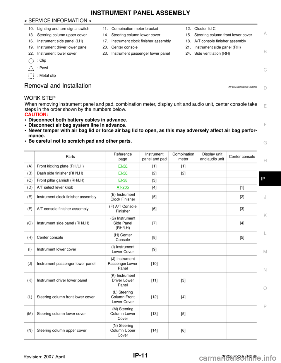
INSTRUMENT PANEL ASSEMBLYIP-11
< SERVICE INFORMATION >
C
DE
F
G H
J
K L
M A
B
IP
N
O P
Removal and InstallationINFOID:0000000001328088
WORK STEP
When removing instrument panel and pad, combination me ter, display unit and audio unit, center console take
steps in the order shown by the numbers below.
CAUTION:
Disconnect both battery cables in advance.
Disconnect air bag system line in advance.
Never temper with air bag lid or force air bag lid to open, as this may adversely affect air bag perfor-
mance.
Be careful not to scratch pad and other parts.
10. Lighting and turn signal switch 11. Combination meter bracket 12. Cluster lid C
13. Steering column upper cover 14. Steering column lower cover 15. Steering column front lower cover
16. Instrument side panel (LH) 17. Instrument clock finisher assembly 18. A/T console finisher assembly
19. Instrument driver lower panel 20. Center console 21. Instrument side panel (RH)
22. Instrument lower cover 23. Instrument passenger lower panel 24. Side ventilation (RH)
: Clip
: Pawl
: Metal clip
Parts Reference
page Instrument
panel and pad Combination
meter Display unit
and audio unit Center console
(A) Front kicking plate (RH/LH) EI-38
[1] [1]
(B) Dash side finisher (RH/LH) EI-38
[2] [2]
(C) Front pillar garnish (RH/LH) EI-38
[3]
(D) A/T select lever knob AT- 2 0 5
[4] [1]
(E) Instrument clock finisher assembly (E) Instrument
Clock Finisher [5] [2]
(F) A/T console finisher assembly (F) A/T Console
Finisher [6] [3]
(G) Instrument side panel (RH/LH) (G) Instrument
Side Panel (RH/LH) [7] [4]
(H) Center console (H) Center
Console [8] [5]
(I) Instrument lower cover (I) Instrument
Lower Cover [9]
(J) Instrument passenger lower panel (J) Instrument
Passenger Lower
Panel [10]
(K) Instrument driver lower panel (K) Instrument
Driver Lower Panel [11] [3]
(L) Steering column front lower cover (L) Steering
Column Front Lower Cover [12] [4]
(M) Steering column lower cover (M) Steering
Column Lower
Cover [13] [5]
(N) Steering column upper cover (N) Steering
Column Upper Cover [14] [6]
3AA93ABC3ACD3AC03ACA3AC03AC63AC53A913A773A893A873A873A8E3A773A983AC73AC93AC03AC3
3A893A873A873A8F3A773A9D3AAF3A8A3A8C3A863A9D3AAF3A8B3A8C
Page 3013 of 3924
![INFINITI FX35 2008 Service Manual
IP-12
< SERVICE INFORMATION >
INSTRUMENT PANEL ASSEMBLY
[]: Number indicates step in removal procedures.
REMOVAL
(A) Front Kicking Plate (RH/LH)
Remove front kicking plate (RH/LH). Refer to EI-38.
(B INFINITI FX35 2008 Service Manual
IP-12
< SERVICE INFORMATION >
INSTRUMENT PANEL ASSEMBLY
[]: Number indicates step in removal procedures.
REMOVAL
(A) Front Kicking Plate (RH/LH)
Remove front kicking plate (RH/LH). Refer to EI-38.
(B](/manual-img/42/57017/w960_57017-3012.png)
IP-12
< SERVICE INFORMATION >
INSTRUMENT PANEL ASSEMBLY
[]: Number indicates step in removal procedures.
REMOVAL
(A) Front Kicking Plate (RH/LH)
Remove front kicking plate (RH/LH). Refer to EI-38.
(B) Dash Side Finisher (RH/LH)
1. Remove plastics nut.
2. Remove dash side finisher (RH/LH). Refer to EI-38
.
(C) Front Pillar Garnish (RH/LH)
Pull to inside of vehicle, disengage metal clips and remove front pillar garnish. Refer to EI-38.
(D) A/T Select Lever Knob
1. Pull down knob cover.
2. Remove lock-pin of select lever knob.
3. Lift up select lever knob and remove select lever knob.
Refer to AT-205, "
Control Device Removal and Installation".
(E) Instrument Clock Finisher
1. Remove screw and then pull back to your side of instrument
clock finisher.
2. Disconnect clips and harness connector, and remove instrument clock finisher.
(F) A/T Console Finisher
(O) Wiper and washer switch (O) Wiper and
Washer Switch [15] [7]
(P) Lighting and turn signal switch (P) Lighting and
Turn Signal Switch [16] [8]
(Q) Steering lock escutcheon (Q) Steering Lock
Escutcheon [17] [9]
(R) Combination meter assembly (R) Combination
Meter Assembly [18] [10]
(S) Cluster lid C (S) Cluster Lid C [19] [1] (T) Display unit and audio unit (T) Display Unit
and Audio Unit [20] [2]
(U) Front defroster grille (RH/LH) (U) Front
Defroster Grille (RH/LH) [21]
(V) Combination meter bracket (V) Combination
Meter Bracket [22]
(W) Side ventilation (RH/LH) (W) Side
Ventilation (RH/LH) [23]
(X) Instrument panel and pad (X) Instrument
Panel and Pad [24]
Parts
Reference
page Instrument
panel and pad Combination
meter Display unit
and audio unit Center console
: Clip
: Pawl
PIIB8535E
3AA93ABC3ACD3AC03ACA3AC03AC63AC53A913A773A893A873A873A8E3A773A983AC73AC93AC03AC3
3A893A873A873A8F3A773A9D3AAF3A8A3A8C3A863A9D3AAF3A8B3A8C