2008 INFINITI FX35 wiring
[x] Cancel search: wiringPage 3855 of 3924
TROUBLE DIAGNOSESWT-15
< SERVICE INFORMATION >
C
DF
G H
I
J
K L
M A
B
WT
N
O P
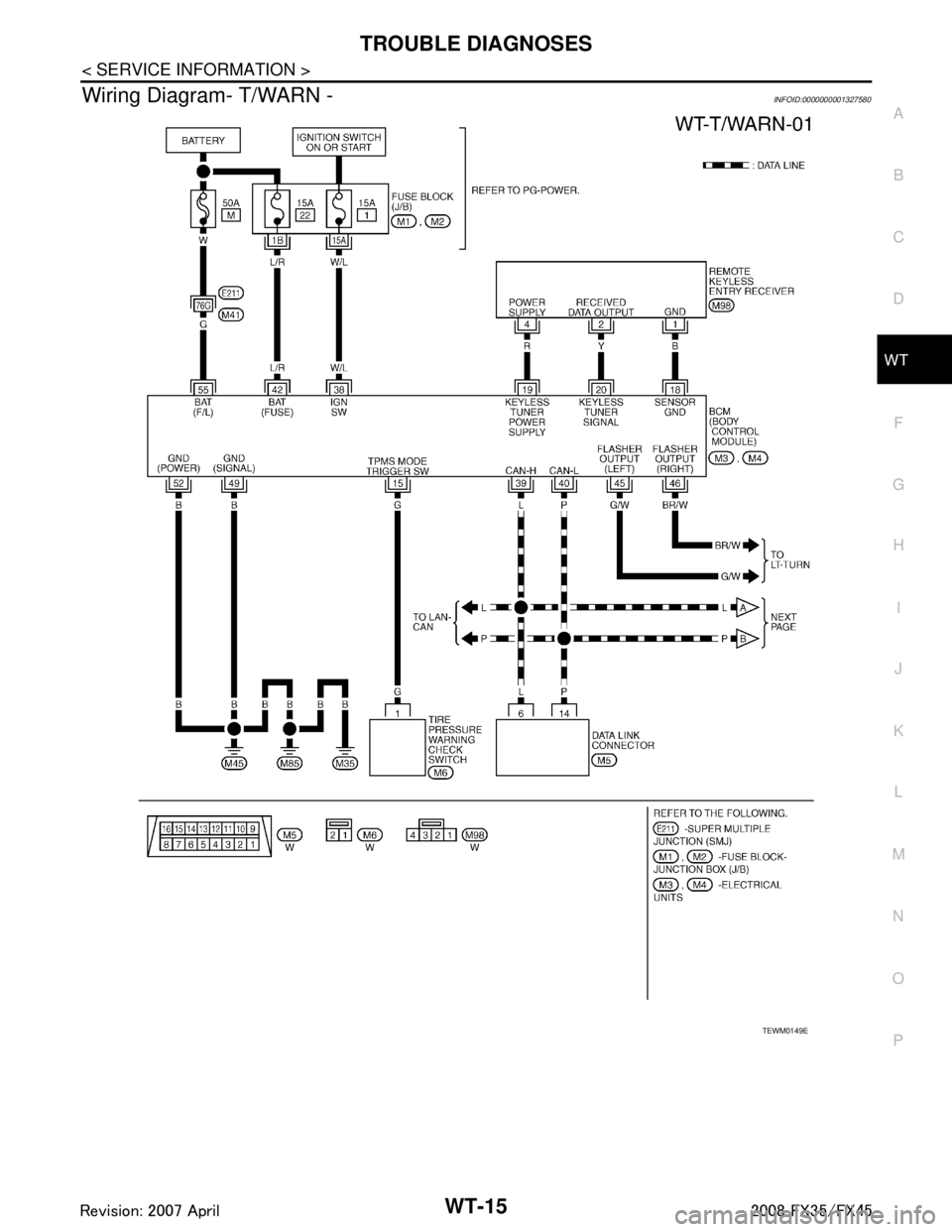
Wiring Diagram- T/WARN -INFOID:0000000001327580
TEWM0149E
3AA93ABC3ACD3AC03ACA3AC03AC63AC53A913A773A893A873A873A8E3A773A983AC73AC93AC03AC3
3A893A873A873A8F3A773A9D3AAF3A8A3A8C3A863A9D3AAF3A8B3A8C
Page 3876 of 3924
WW-1
ELECTRICAL
C
DE
F
G H
I
J
L
M
SECTION WW
A
B
WW
N
O P
CONTENTS
WIPER, WASHER & HORN
SERVICE INFORMATION .. ..........................3
PRECAUTION ................................................ .....3
Precaution for Supplemental Restraint System
(SRS) "AIR BAG" and "SEAT BELT PRE-TEN-
SIONER" ............................................................. ......
3
Precaution for Procedure without Cowl Top Cover ......3
FRONT WIPER AND WASHER SYSTEM ..........4
Component Parts and Harness Connector Loca-
tion ...................................................................... ......
4
System Description ...................................................4
CAN Communication System Description .................6
CAN Communication Unit .........................................7
Schematic .................................................................7
Wiring Diagram - WIPER - ........................................8
Terminal and Reference Value for BCM .................10
Terminal and Reference Value for IPDM E/R .........14
How to Proceed with Trouble Diagnosis .................14
Preliminary Check ...................................................14
CONSULT-III Functions (BCM) ...............................15
CONSULT-III Functions (IPDM E/R) .......................16
Front Wiper Does Not Operate ...............................17
Front Wiper Does Not Return to Stop Position .......18
Only Front Wiper Low Does Not Operate ...............19
Only Front Wiper High Does Not Operate ...............20
Only Front Wiper Intermittent Does Not Operate ....21
Front Wiper Interval Time Is Not Controlled by Ve-
hicle Speed .............................................................
21
Front Wiper Intermittent Operation Switch Posi-
tion Cannot Be Adjusted .........................................
22
Wiper Does Not Wipe When Front Washer Oper-
ates .........................................................................
22
After Front Wiper Operate for 10 Seconds, They
Stop for 20 Seconds, and After Repeating the Op-
eration Five Times, They Become Inoperative ........
22
Front Wiper Does Not Stop .....................................23
Removal and Installation of Front Wiper Arms, Ad-
justment of Wiper Arms Stop Location ....................
23
Removal and Installation of Front Wiper Drive As-
sembly ................................................................. ....
24
Disassembly and Assembly of Front Wiper Drive
Assembly ............................................................. ....
25
Washer Nozzle Adjustment .....................................25
Washer Tube Layout ...............................................27
Removal and Installation of Front Washer Nozzle ....27
Removal and Installation of Front Washer Tube
Joint .........................................................................
27
Inspection of Washer Nozzle ...................................27
Inspection of Front Wiper and Washer Switch Cir-
cuit ...........................................................................
28
Removal and Installation of Front Wiper and
Washer Switch .........................................................
28
Removal and Installation of Washer Tank ...............28
Removal and Installation of Front and Rear Wash-
er Pump ...................................................................
29
REAR WIPER AND WASHER SYSTEM ..........30
Component Parts and Harness Connector Loca-
tion ...........................................................................
30
System Description ..................................................30
Wiring Diagram - WIP/ R - .......................................32
Terminal and Reference Value for BCM ..................33
How to Proceed with Trouble Diagnosis ..................35
Preliminary Check ...................................................36
CONSULT-III Functions (BCM) ...............................36
Rear Wiper Does Not Operate ................................37
Rear Wiper Does Not Return to Stop Position ........39
Only Rear Wiper ON Does Not Operate ..................40
Only Rear Wiper INT Does Not Operate .................40
Wiper Does Not Wipe When Rear Washer Oper-
ates ..........................................................................
40
Rear Wipers Do Not Stop ........................................40
Removal and Installation of Rear Wiper Arm, Ad-
justment of Wiper Arms Stop Location ....................
40
Removal and Installation of Rear Wiper Blade ........41
Removal and Installation of Rear Wiper Motor ........42
Washer Nozzle Adjustment .....................................43
Washer Tube Layout ...............................................43
Removal and Installation of Washer Nozzle ............43
Check Valve ............................................................44
3AA93ABC3ACD3AC03ACA3AC03AC63AC53A913A773A893A873A873A8E3A773A983AC73AC93AC03AC3
3A893A873A873A8F3A773A9D3AAF3A8A3A8C3A863A9D3AAF3A8B3A8C
Page 3877 of 3924

WW-2
Inspection of Front Wiper and Washer Switch Cir-
cuit ..........................................................................
44
Removal and Installation of Rear Wiper and
Washer Switch ........................................................
44
Removal and Installation of Washer Tank ..............44
Removal and Installation of Front and Rear Wash-
er pump ..................................................................
44
POWER SOCKET ..............................................45
Wiring Diagram - P/SCKT - ................................. ...45
Removal and Installation of Front Power Socket -
1 ........................................................................... ...
45
Removal and Installation of Front Power Socket -
2 ..............................................................................
46
Removal and Installation of Rear Power Socket .....46
Removal and Installation of Luggage Room Power
Socket .................................................................. ...
46
HORN .................................................................48
Wiring Diagram - HORN - .................................... ...48
Removal and Installation .........................................48
3AA93ABC3ACD3AC03ACA3AC03AC63AC53A913A773A893A873A873A8E3A773A983AC73AC93AC03AC3
3A893A873A873A8F3A773A9D3AAF3A8A3A8C3A863A9D3AAF3A8B3A8C
Page 3878 of 3924
PRECAUTIONWW-3
< SERVICE INFORMATION >
C
DE
F
G H
I
J
L
M A
B
WW
N
O P
SERVICE INFORMATION
PRECAUTION
Precaution for Supplemental Restraint System (SRS) "AIR BAG" and "SEAT BELT
PRE-TENSIONER"
INFOID:0000000001612916
The Supplemental Restraint System such as “A IR BAG” and “SEAT BELT PRE-TENSIONER”, used along
with a front seat belt, helps to reduce the risk or severi ty of injury to the driver and front passenger for certain
types of collision. This system includes seat belt switch inputs and dual stage front air bag modules. The SRS
system uses the seat belt switches to determine the front air bag deployment, and may only deploy one front
air bag, depending on the severity of a collision and whether the front occupants are belted or unbelted.
Information necessary to service the system safely is included in the “SUPPLEMENTAL RESTRAINT SYS-
TEM” and “SEAT BELTS” of this Service Manual.
WARNING:
• To avoid rendering the SRS inoper ative, which could increase the risk of personal injury or death in
the event of a collision which would result in air bag inflation, all maintenance must be performed by
an authorized NISSAN/INFINITI dealer.
Improper maintenance, including in correct removal and installation of the SRS, can lead to personal
injury caused by unintentional act ivation of the system. For removal of Spiral Cable and Air Bag
Module, see the “SUPPLEMEN TAL RESTRAINT SYSTEM”.
Do not use electrical test equipm ent on any circuit related to the SRS unless instructed to in this
Service Manual. SRS wiring harnesses can be identi fied by yellow and/or orange harnesses or har-
ness connectors.
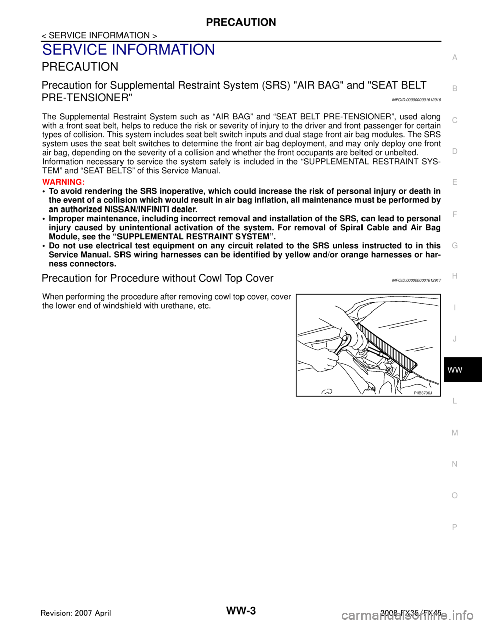
Precaution for Procedur e without Cowl Top CoverINFOID:0000000001612917
When performing the procedure after removing cowl top cover, cover
the lower end of windshield with urethane, etc.
PIIB3706J
3AA93ABC3ACD3AC03ACA3AC03AC63AC53A913A773A893A873A873A8E3A773A983AC73AC93AC03AC3
3A893A873A873A8F3A773A9D3AAF3A8A3A8C3A863A9D3AAF3A8B3A8C
Page 3881 of 3924

WW-6
< SERVICE INFORMATION >
FRONT WIPER AND WASHER SYSTEM
Using combination switch reading function, BCM detects ON/OFF status of INT VOLUME 1, 2, and 3.
When combination switch status is as listed below, BCM det ermines that it is wiper intermittent dial position 1.
INT VOLUME 1: ON (Continuity exists bet ween combination switch output 3 and input 1.)
INT VOLUME 2: ON (Continuity exists bet ween combination switch output 5 and input 1.)
INT VOLUME 3: ON (Continuity exists bet ween combination switch output 4 and input 2.)
BCM determines front wiper intermittent operation delay in terval from wiper intermittent dial position 1 and
vehicle speed, and sends wiper request signal (INT) to IPDM E/R.
AUTO STOP OPERATION
With wiper switch turned OFF, wiper motor will conti nue to operate until wiper arms reach windshield base.
When wiper arms are not located at base of winds hield with wiper switch OFF, ground is provided
from IPDM E/R terminal 21
to front wiper motor terminal 1, in order to continue wiper motor operation at low speed.
When wiper arms reach base of windshield, fr ont wiper motor terminals 5 and 2 are connected,
and Ground is supplied
to IPDM E/R terminal 32
through front wiper motor terminals 5 and 2
through grounds E21, E50 and E51.
Then the IPDM E/R sends auto stop operati on signal to BCM through CAN communication.
When the BCM receives auto-stop operation signal, BCM sends wiper stop signal to IPDM E/R through CAN
communication.
IPDM E/R stops wiper motor. Wiper motor will then stop wiper arms at the STOP position.
WASHER OPERATION
When wiper switch is in front wiper washer position wit h ignition switch on, BCM detects front wiper switch is
on the washer position by BCM wiper switch reading function (Refer to "COMBINATION SWITCH READING
FUNCTION"), combination switch (wiper switch) ground is supplied
to combination switch terminal 13
through front and rear washer pump terminal 1
to front and rear washer pump terminal 2
through combination switch terminal 11
to combination switch terminal 12
through grounds M35, M45 and M85.
With ground supplied, front and rear washer pump is operated.
When BCM detects that front and rear washer pump has operated for 0.4 seconds or linger, BCM operates
front wiper motor for low speed.
When BCM detects washer switch is OFF, low s peed operation cycles approximately 2 times and stops.
MIST OPERATION
When wiper switch is turned to MIST position, wiper low speed operation cycles once and then stops.
For additional information about wiper operation under this condition, Refer to "LOW SPEED WIPER OPERA-
TION".
If switch is held in MIST position, low speed operation continues.
FAIL-SAFE FUNCTION
If an abnormality occurs in CAN communications, IPDM E/ R holds the condition just before fail-safe status is
initiated until ignition switch is turned OFF. (If wipers we re operating in LO just before the initiation of fail-safe
status, they continue to operate in LO until ignition switch is turned OFF.)
COMBINATION SWITCH READING FUNCTION
Refer to BCS-4, "System Description".
CAN Communication System DescriptionINFOID:0000000001328544
CAN (Controller Area Network) is a serial communication line for real time application. It is an on-board multi-
plex communication line with high data communication speed and excellent error detection ability. Many elec-
tronic control units are equipped onto a vehicle, and each control unit shares information and links with other
control units during operation (not independent). In CA N communication, control units are connected with 2
communication lines (CAN H line, CAN L line) allowing a high rate of information transmission with less wiring.
Each control unit transmits/receives data but selectively reads required data only.
3AA93ABC3ACD3AC03ACA3AC03AC63AC53A913A773A893A873A873A8E3A773A983AC73AC93AC03AC3
3A893A873A873A8F3A773A9D3AAF3A8A3A8C3A863A9D3AAF3A8B3A8C
Page 3883 of 3924
WW-8
< SERVICE INFORMATION >
FRONT WIPER AND WASHER SYSTEM
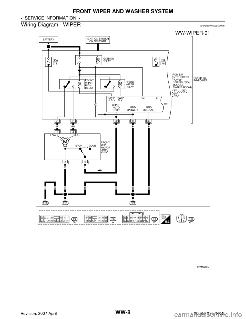
Wiring Diagram - WIPER -
INFOID:0000000001328547
TKWM0663E
3AA93ABC3ACD3AC03ACA3AC03AC63AC53A913A773A893A873A873A8E3A773A983AC73AC93AC03AC3
3A893A873A873A8F3A773A9D3AAF3A8A3A8C3A863A9D3AAF3A8B3A8C
Page 3889 of 3924
WW-14
< SERVICE INFORMATION >
FRONT WIPER AND WASHER SYSTEM
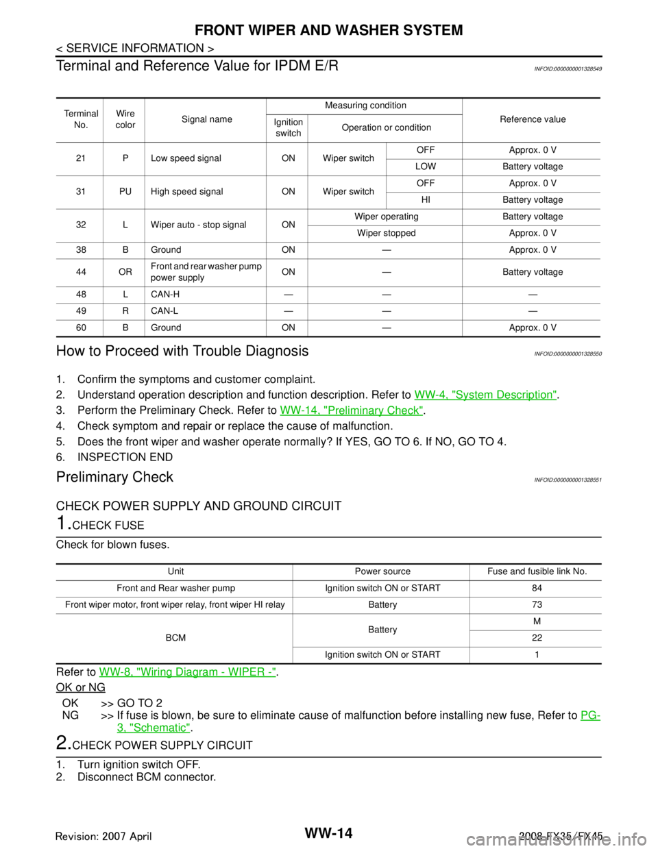
Terminal and Reference Value for IPDM E/R
INFOID:0000000001328549
How to Proceed with Trouble DiagnosisINFOID:0000000001328550
1. Confirm the symptoms and customer complaint.
2. Understand operation description and function description. Refer to WW-4, "
System Description".
3. Perform the Preliminary Check. Refer to WW-14, "
Preliminary Check".
4. Check symptom and repair or r eplace the cause of malfunction.
5. Does the front wiper and washer operate norma lly? If YES, GO TO 6. If NO, GO TO 4.
6. INSPECTION END
Preliminary CheckINFOID:0000000001328551
CHECK POWER SUPPLY AND GROUND CIRCUIT
1.CHECK FUSE
Check for blown fuses.
Refer to WW-8, "
Wiring Diagram - WIPER -".
OK or NG
OK >> GO TO 2
NG >> If fuse is blown, be sure to eliminate caus e of malfunction before installing new fuse, Refer to PG-
3, "Schematic".
2.CHECK POWER SUPPLY CIRCUIT
1. Turn ignition switch OFF.
2. Disconnect BCM connector.
Te r m i n a l No. Wire
color Signal name Measuring condition
Reference value
Ignition
switch Operation or condition
21 P Low speed signal ON Wiper switch OFF Approx. 0 V
LOW Battery voltage
31 PU High speed signal ON Wiper switch OFF Approx. 0 V
HI Battery voltage
32 L Wiper auto - stop signal ON Wiper operating Battery voltage
Wiper stopped Approx. 0 V
38 B Ground ON — Approx. 0 V
44 OR Front and rear washer pump
power supply ON — Battery voltage
48 L CAN-H — — —
49 R CAN-L — — —
60 B Ground ON — Approx. 0 V
Unit Power source Fuse and fusible link No.
Front and Rear washer pump Ignition switch ON or START 84
Front wiper motor, front wiper rela y, front wiper HI relay Battery 73
BCM BatteryM
22
Ignition switch ON or START 1
3AA93ABC3ACD3AC03ACA3AC03AC63AC53A913A773A893A873A873A8E3A773A983AC73AC93AC03AC3
3A893A873A873A8F3A773A9D3AAF3A8A3A8C3A863A9D3AAF3A8B3A8C
Page 3907 of 3924
WW-32
< SERVICE INFORMATION >
REAR WIPER AND WASHER SYSTEM
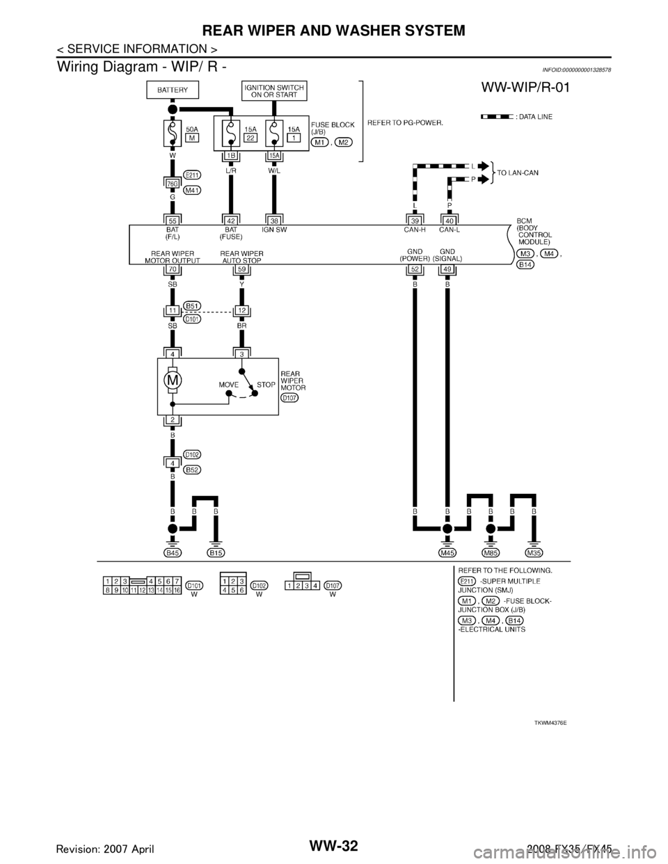
Wiring Diagram - WIP/ R -
INFOID:0000000001328578
TKWM4376E
3AA93ABC3ACD3AC03ACA3AC03AC63AC53A913A773A893A873A873A8E3A773A983AC73AC93AC03AC3
3A893A873A873A8F3A773A9D3AAF3A8A3A8C3A863A9D3AAF3A8B3A8C